1
Modeling of Different Winding Configurations for Fault Tolerant Permanent Magnet Machines to Restrain Inter-turn Short-circuit Current Puvan Arumugam, Tahar Hamiti, Chris Gerada, Member, IEEE
Abstract-- This paper describes an analytical model to evaluate the Short-Circuit (SC) current resulting from an inter-turn fault by computing the self and mutual inductances under shortcircuit fault condition. Two different concentrated winding configurations, i.e. horizontally and vertically placed conductors in the slot of a Fault tolerant Permanent Magnet Synchronous Machine (FT-PMSM) are considered. By computing the associated slot-leakage and air-gap fluxes, the self inductance of both healthy and faulty windings as well as the mutual inductance between them, the short-circuit current can be determined for any position and number of shorted turns. The proposed model is verified with finite-element analysis and validated experimentally. It will be shown that the magnitude of an inter-turn short-circuit current depends on both the number of shorted turns and their position in the slot. The measured short-circuit inductance shows that a new proposed concentrated vertical winding configuration can inherently limit the shortcircuit current and reduce its dependence on the position within the slot. Index Terms-- Concentrated windings, Fault tolerant, Permanent Magnet, Short-circuit, leakage flux.
I. INTRODUCTION
W
ith the current move towards more electrical transport, the requirements for safety and reliability of electrical system increased significantly. Not exhaustively, examples of safety critical applications include fuel pumps and actuators for aerospace applications and electrical steering for automotive application. In such applications it is essential to ensure the drive is capable of continuing operation in the event of any failure. Such a drive system is known as fault tolerant drive system. Due to its robustness, easiness to manufacture and low magnetic interaction between phases, Switched Reluctance (SR) machines constitute a good choice for fault tolerant drives [1], [2]. However these qualities are overshadowed by a relatively high torque ripple and acoustic noise. Permanent The authors are all with the Power Electronics, Machines and Control Group, Faculty of Engineering, the University of Nottingham, University Park, Nottingham, NG7 2RD. UK. Puvan Arumugam (e-mail:
[email protected]) Tahar Hamiti(e-mail:
[email protected]) Chris Gerada (e-mail:
[email protected])
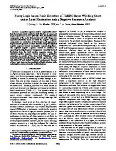
magnets machines are more popular compared to SR machines in safety critical applications due to their greater torque density and subsequently higher power density. This is a crucial advantage especially in the aircraft industry because a reduction in weight increases fuel efficiency making it more environmental friendly. A typical fault tolerant PM machine’s topology includes number of design futures [3]-[5] to enhance its fault tolerant capability as shown by the cross sectional view in Fig.1, where: The phase windings are separated physically and magnetically using concentrated winding. Consequently, the fault that occurs in a phase will not propagate to adjacent phases. Electrical isolation between the phases accomplished by employing a separate voltage fed inverter for each phase or for groups of phases. The phase winding is designed to have one per-unit self inductance in order to limit the short-circuit current to its rated value under fault condition as well as to minimize the resulting braking torque. The machine drive is able to produce rated power continuously in the event of failure by overrating the machine design to handle the increased current loading during faulty operation.
Fig. 1. Cross sectional view of a 12slot//14 pole FT- PMSM
Although a machine might fulfill these design criteria, a winding inter-turn short-circuit fault can still be critical because of the resulting excessive current which can cause a
2
catastrophic failure. As a remedial action, this current can be controlled by shorting the whole phase through the power converter switches [5]. It forces all the turns in the phase to share the net winding magneto motive force (mmf). As a result the current in the shorted turn reduces. However, this action is ineffective for a single turn short-circuit fault due to its low impedance and as a consequence a significantly high fault current compared to the rated current still persists[6][8]. This current depends not only on the number of shorted turns but also on their position in the slot. To compute its variation with the position within the coil and the number of shorted turns Finite Element Method (FEM) analysis can be used but, despite its accuracy, it is time consuming, limiting the flexibility of any parametric study [9]. This paper describes an analytical model to evaluate the inter-turn short-circuit current by evaluating associated winding leakage fluxes. Two different concentrated winding [10] configurations which are distributed in the slots of a Fault Tolerant Permanent Magnet Synchronous Machine (FT-PMSM) are considered. By quantifying the slot-leakage and air-gap fluxes the self inductance of both healthy and faulty turns as well as the mutual inductance between them can be evaluated. The evaluation of inductances as a function of the fault position facilitates the determination of the shortcircuit current before and after the application of remedial action which consists of short-circuiting the phase terminals. The effectiveness of the proposed technique is verified by both FEM and experimental results.
II. BEHAVIOR OF THE INTER-TURN SHORT-CIRCUIT FAULT An inter-turn winding fault causes a change in winding resistance, inductance and also the electrical circuit of the winding. During an inter-turn short circuit fault, the healthy and the shorted turns behave as two separate circuits which are magnetically coupled, but electrically isolated [3], as illustrated in Fig.2.
(a)
(b)
dI 1 dI L m s e1 (t ) dt dt dI s dI 0 I s (t ) R s L s L m 1 e 2 (t ) dt dt (2)
V1 (t ) I 1 (t ) R h L h
(1)
where, - e1: electromotive force (emf) in the healthy (Nh) turns - e2: emf in the shorted (Ns) turns - I1: phase current - Is: induced current in the shorted (Ns) turns - Lh: self inductances of healthy (Nh) turns - Ls: self inductances of shorted (Ns) turns - Lm: mutual inductance between Nh and Ns turns From (1) and (2) it can be seen that the induced current in the shorted turns (Is) can be evaluated once the inductances and resistances are determined. Whilst the dc resistances (neglecting skin and proximity effects) are independent of the shorted turns’ position in the slot, the inductances are position-dependant. Since the short-circuit current is inductance-limited at rated speed, an accurate knowledge of the different inductances is required to evaluate correctly the short-circuit current. III. COMPUTATION OF THE SHORT -CIRCUIT INDUCTANCE AND CURRENT FOR HORIZONTAL WINDING CONFIGURATION
The methodology proposed in [7], [11] is used with some modifications to suit any fault tolerant machine’s geometry. The current in the shorted turns is then derived before and after the application of the remedial action (i.e. shortcircuiting the entire phase) and the results are compared with the FEM ones. According to Fig.3 the short-circuited adjacent turns (Ns) are sandwiched by the remaining healthy turns. x represents the position of the shorted turns. Thus, the inductances can be estimated by quantifying the associated slot-leakage flux [11] at the position of the fault.
(c)
Fig. 2. (a) A healthy phase winding (b) A phase winding under a short-circuit fault condition (c) Equivalent circuit of a FT-PM machine under inter-turn short circuit condition
Since the mutual coupling between phases for a properly designed FT-PMSM can be neglected [4], the differential equations (1) and (2) governing a faulty phase circuits will allow the computation of the short-circuit current.
Fig. 3. Flux representation used in the modeling of horizontal winding
In the modeling process, the following assumptions were made: 1. The laminated magnetic material has an infinite permeability;
3
2. The concentrated winding is placed horizontally and uniformly in the slot; 3. The slot-leakage flux is always parallel to circumferential direction as shown in Fig.3; 4. The end-leakage flux is negligible. As shown in Fig.3, to calculate the self inductance of Ns shorted turns, the total leakage flux can be divided into five parts: A. the slot leakage flux ( so ) linking the slot wedge and the slot opening associated to the shorted turns; B. the slot leakage flux ( 1 ) linking the height (hb ha ) associated to the shorted turns; C. the slot leakage flux (2 ) linking the height (h s hb ) associated to the shorted turns; D. the leakage flux associated to the tooth-tip and air gap.
with (dx) being the length increment along the slot depth, (l) the flux path length across the slot width and (Ns) the number of shorted turns. The above assumes a trapezoidal slot geometry and uniformly distributed turns along the slot height [7]. l and Ns can thus equal to : l S w 2hs x tan
Ns
(6)
N x ha hs
(7)
By integrating (5) the total flux linking the height (hb ha ) of the Ns shorted turns is hb
d
1
ha
A. Flux ( so ) linking the slot wedge and the slot opening The flux ( so ) linking the slot wedge and the slot opening associated to the shorted turns can be estimated by quantifying the permeance (Ps) of both rectangular slot opening and trapezoidal slot wedge [11]. Hence, the flux ( so ) is given as follows
N o l stk I ha hs
N o l stk hs
2
x ha 2 d x S w 2h s x tan
2
I (a b)(c S w 2 ) d e 3 8 tan( )
(8)
where: b ln S w 2(hs ha ) tan( )
h S 1 o l stk t tan ln w b 2 bo o
2 Ns I
(3)
e 2S w tan( )[ 2(b a)(ha hs ) (hb ha )]
C. Flux (2 ) linking the height of (h s hb ) The flux linking the height (hs –hb) associated to the shorted turns can be estimated by quantifying the corresponding trapezoidal slot permeance (Pt) [11]: Pt o l stk
The total flux linking the width (hb – ha) of the shorted turns (Ns) can be evaluated by integrating the flux density over the corresponding area (A). Applying the Ampere’s law, the flux can be written as: (4)
and the flux increment can then be written as: N s2 I l stk dx l
S 2 tan h s hb 1 ln w 2 tan Sw
(9)
and the resulting flux linkage is given by:
B. Flux (1 ) linking the height (hb ha )
NsI l
c [2(hs ha) tan( )]2 d 2 tan( ) 2[ha (3ha 2hs ) hb (hb 4ha 2hs )
where: - l stk : axial length of the laminated core - o : permeability of air - bo : the slot opening - S w : the slot width - ht : the tooth-tip height - : the slot wedge angle - I : the current - Ns : the number of shorted turns
d B dA o
hb
a ln S w 2( hs hb ) tan( )
so Ps N s 2 I
B o H o
(5)
2 Pt N s 2 I
(10)
The total slot leakage flux linking the shorted turns is: s so 1 2
(11)
Using the same derivation process, the slot-leakage flux h linking all the healthy turns as well as the mutual flux m between the healthy and the shorted turns can be evaluated. The equations are derived respectively in the appendix.