J. Ind. Geophys. Union ( October 2006 ) Vol.10, No.4, pp.303-312
Modeling of Indian Ionosphere using MMSE Estimator for GAGAN Applications D.Venkata Ratnam and A.D.Sarma Research and Training Unit for Navigational Electronics, Osmania University, Hyderabad – 500 007 E-mail:
[email protected]
ABSTRACT With the advent of Global Positioning System (GPS), there has been significant change in aircraft navigation. For improving positional accuracy of GPS and for wide coverage, a Satellite Based Augmentation System (SBAS) is being developed in India popularly known as GAGAN. As the Indian ionosphere is characterized by large gradients, intense irregularities and an equatorial anomaly condition, a suitable ionospheric model is necessary for GAGAN. In this paper, an algorithm based on Minimum Mean Square Error (MMSE) technique is presented for computing the vertical delay at each Ionospheric Grid Point (IGP) and the Grid Ionospheric Vertical Error (GIVE). Several days of GPS data corresponding to multiple stations provided by Space Applications Centre (SAC), Ahmedabad is processed and applied to these models. It is found from the results that the estimated error bound on IGP delay (i.e., GIVE) is less than 2.0 m indicating that this model is one of the contenders for GAGAN applications.
INTRODUCTION Global Positioning System (GPS) is a satellite based navigation system developed by Department of Defence (DoD), USA and gives three dimensional user position. Stand-alone GPS system is not sufficient for high precision applications like Precision Approach (PA) due to several errors such as ionospheric time delays. Therefore, augmentation is necessary to improve its accuracy. For meeting the stringent navigation requirements of integrity, availability and continuity of service, Satellite Based Augmentation Systems (SBAS) for GPS was planned to provide corrections and confidence bounds on the user errors. The first SBAS system was initiated by USA in early nineties for providing coverage of Continental United States (CONUS) region (Walter et al.,1994). This is popularly known as Wide Area Augmentation System (WAAS). Like in USA, the Airports Authority of India (AAI) has decided to implement an indigenous satellite based regional GPS augmentation system, known as GAGAN as a part of the CNS/ATM requirements of civil aviation in India (Ramalingam et al., 2002a). The GAGAN system for this purpose will be implemented jointly by the Indian Space Research Organization (ISRO) and Airport Authority of India (AAI). One of the important tasks of GAGAN is the development of a suitable ionospheric model. Grid models are
preferred over analytical ionospheric model as the existing grid based models are found to give better estimators in the mid-latitude regions, where the spatial and temporal changes in the structure of the ionosphere are fairly smooth during the magnetically quiet conditions (Lejeune et.al., 2002). But, the ionospheric conditions in low-latitude regions present more range delays due to spatial and temporal variations even during the magnetically quiet and also in disturbed ionospheric conditions. Therefore, these models may not be suitable in the low latitude and equatorial regions such as India and Brazil. In view of the above, the validity of the existing grid based models over the GAGAN region is to be studied thoroughly. One of the grid models used for the WAAS is Inverse Distance Weighted (IDW) with Klobuchar model. MITRE’s Centre for Advanced Aviation System Development (CAASD) investigated an alternative algorithm based on the MMSE Technique (Lejeune and El-Arini, 1999). This paper describes the applicability of MMSE algorithm for GAGAN. GAGAN To facilitate the accuracy required Category-1(CAT-1) precession approach landing of aircrafts, augmentation of GPS is planned through regional SBAS called GAGAN by ISRO and AAI. The objectives of GAGAN
303
D.Venkata Ratnam and A.D.Sarma
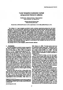
are to provide the navigation performance parameters such as accuracy, integrity, time to alert, continuity and availability to the Global Navigation Satellite System (GNSS) users over the Indian service region (Ramalingam 2002b). GAGAN architecture consists of i) Indian Reference Stations (INRESs) ii) Indian Mission Control Center (INMCC) iii) Indian Navigation Land Uplink Station (INLUS), iv) The GEO Payload and, v) User GNSS receivers. Initial studies are carried out by Sarma, et al (2000) on placement of TEC stations for Indian region. Based on this, 20 TEC stations are placed at surveyed locations over widely separated geographical area in India (Fig.1). The networks of 20 TEC stations and 8 INRESs receive and monitor the GPS signals for estimating the clock, ephemeris and ionospheric error corrections. The INRESs and TEC stations acquire broadcast ephemeris and pseudorange data from all the GPS and GEO satellites in view. Data from these stations are transmitted to the INMMC, where the validity of the signals from each satellite is assessed and corrections are computed. The INMCC consists of a mainframe computer and a host of secondary
computers connected to a network of INRES and TEC stations (Suryanarayana Rao & Pal 2004). The INMMC also develop the ephemeris and clock information of the Geostationary Earth Orbiting Satellites (GEOs). All these data are packed into GAGAN message and is sent to the INLUS. The INLUS uplink this message on 6455.2 MHz to the GEOS that broadcast GPS like signals to the GNSS users. INMCC is collocated with the INLUS at Bangalore. One 40kg navigation payload with EIRP of 33.5 dBW is planned in the Indian Ocean Region (IOR) between the orbital location 48° to 100 E longitude through GSAT4 to meet the objectives of GAGAN (Kibe 2003). Ionospheric delay is one of the prominent errors in the GAGAN that limit the positional accuracy. The ionospheric delay corrections are broadcast as vertical delay estimates at specified Ionospheric Grid Points (IGPs) in the predefined global IGP grid to suitably modify single frequency GPS receivers. The predefined global IGP grid consists of 1808 IGPs. For providing the ionospheric error corrections over the GAGAN service region, 60 IGPs are identified (Sarma et al., 2000).
Figure 1. GAGAN TEC receiver stations 304
Modeling of Indian Ionosphere using MMSE Estimator for GAGAN Applications
Estimation of IPP delays The intersection of line of sight from receiver to satellite and the shell defined at a designated height of 350 km is known as an IPP. The GPS receiver measures the slant TEC for each visible satellite. The slant IPP delay (Ds) is obtained from the slant TEC using standard formula.
Ds =
40.3 × TEC cf 2
meters
(1)
Where, c is velocity of light and f is the L1 signal frequency (1575.42 MHz) Conversion of slant delay to vertical delay is necessary for the analysis. Therefore, slant TEC is multiplied by a mapping function which is defined as (Langely et al, 2002)
⎛ ⎛ R × cos(el ) ⎞ 2 ⎞ ⎟ ⎟ MF = ⎜1 − ⎜⎜ e ⎜ ⎝ Re + hiono ⎟⎠ ⎟ ⎝ ⎠
−
1 2
(2)
Where, Re = Radius of the Earth in Kms el= Elevation angle of the GPS satellite in degrees hiono = Ionospheric mean height in Kms The corresponding IPP locations are estimated for each visible satellite (WAASMOPS, 1998). IGP delay estimation MMSE is based on the principle of post estimation of the expectation of the square of the error between
the measured delay and estimated delay. The ionospheric grid algorithm presented in this paper corresponds to a fairly straightforward application of the well-known MMSE formulation (Kailath, 1981). The design of the ionospheric grid algorithm presented in this paper computes the vertical delay and GIVE at each IGP by using of two key assumptions: 1. It assumes that the required statistics of vertical delays (mean and variance) can be computed from the available set of ionospheric measurements, and that these statistics remain constant over the entire grid. They adequately characterize the vertical delay distribution at every point of the grid. 2. The design assumes that the correlation between the vertical delays at any two points is solely a function of the distance between two points. Fig.2. Shows implementation steps of ionospheric grid algorithm based on MMSE estimator. Slant TEC measurements from a network of Dual frequency GPS Receivers are mapped to vertical TEC measurements. The vertical delays at specified IGPs are computed using MMSE estimator. These ionospheric corrections along with GIVEs will be transmitted to the user via GEO satellite for correcting his own position. MMSE algorithm steps The MMSE algorithm computes the vertical delays for every epoch (60 seconds) at the IGPs( xˆ ) from the vertical delays (y) derived from the slant delay measurements at the TEC stations IPPs as follows (Lejeune and El-Arini, 1999).
Figure 2. Implementation steps of Ionospheric grid algorithm for GAGAN 305
D.Venkata Ratnam and A.D.Sarma
Step 1 The mean value , and variance , of all vertical delay measurements at the current epoch are computed. These statistics are then assumed to characterize all points in the grid, including all IGPs and all TEC stations’ IPPs, i.e., and number of IGPs and IPPs.
where i and j are
Step 2 The initial state estimate has a covariance matrix that specifies how accurately it approximates the initial state. The initial covariance is a diagonal matrix (Rxx), which can be formed as, (3) Step 3 The covariance (Ryy) and cross covariance matrices (R xy), are computed by assuming an exponential decorrelation function with a constant decorrelation distance of 800 kilometers. In other words, the elements of the Rxy and Ryy matrices are computed from the following formulas:
[R [R
xy
yy
] (i, j )] = σ
(i, j ) = σ xσ y e − d ( xi , y i ) / D 2 y
e − d ( yi , yi ) / D
(4) (5)
where D=800 Km, d(xi,yi) is the distance in kms between xith IGP and yjth IPP locations, and d(yi,yj) is the distance in kms between IPP locations.. Step 4 The vertical ionospheric delay at each IGP( xˆ ) is estimated as, (6) The corresponding vector of error variances ( σ estimated as.
2 e)
is
(7) The error variances are essential for estimating error bounds of IGP vertical delays. GIVE algorithm GIVE is essentially an estimate of the 99.9th percentile of the post-correction ionospheric delay error distribution for user IPPs in the neighborhood of the selected IGP. Initially, the user grid is updated by setting the vertical delays at the IGP equal to the
306
most recently computed vertical delays. Afterwards, the GIVE (in meters) is computed at each IGP as (Lejeune and El-Arini, 1999),
(
GIVEi = RG 3.29e d / DGIVE max(σ e2 )
)
(8)
Where 3.29 is a constant factor intended to yield a GIVE corresponding to the 99.9th percentile of the ionospheric delay post-correction errors, d is the distance in kms between the IGP and the IPP closest to it, and DGIVE is a constant decorrelation parameter equal to 800 Kms, the maximum at IGP i is calculated using Eq.(8). Finally the function RG rounds the GIVE value according to GIVE indicator that can be accommodated by the message (WAAS MOPS, 1998). The computation of GIVE is not constrained in any way by the number of location of neighboring TEC stations IPPs. The exponential factor in Eq.(4) is intended to capture the growth in uncertainty associated with a GIVE estimate when the distance to the nearest IPP increases. This eliminates the need for a limitation on the number and location of neighboring IPPs (Lejeune and El-Arini, 1999). GPS data processing The GPS data obtained from SAC, Ahmedabad consists of 23 parameters. Out of these, only 7 parameters namely SV number, week number, seconds of the week, elevation, azimuth, TEC and DTEC are considered for analysis. In this paper, 12 stations data over the Indian region is considered for the analysis. These data are processed and stored in a separate data file in EXCEL format. The data are sorted with respect to seconds of the week so that data corresponding to a particular epoch can be identified easily. This data are used for calculating other required parameters for estimating the delays at IGPs and GIVE. RESULTS AND DISCUSSION In the analysis, the data corresponding to 2 epochs on 7th and 8th April 2004 are considered. The first epoch was at 14.00 Hrs (LT), April 7, 2004. At this time, 98 IPPs due to 12 stations were recorded. As mentioned in the previous section, latitude and longitudes of these IPPs are computed. The GPS slant TEC data is mapped on to vertical TEC by using mapping function (Eq.2). Using this data, delays at 11 IGPs and corresponding GIVEs are estimated by MMSE estimator. The IPP and IGP locations are shown in Fig.3. The latitude and longitude of IGPs and the corresponding vertical delays and GIVEs are
Modeling of Indian Ionosphere using MMSE Estimator for GAGAN Applications
presented in Table 1. The results show that a maximum of 10.56m and a minimum of 6.13m ionospheric vertical delay were occurred at IGPs located at (150 N 750 E) and (200 N 750 E) respectively. Normally ionospheric delay increases to maximum at afternoon (14.00 Hrs) and gradually decreases towards midnight. It is found from the results that the estimated error bound on IGP delay (i.e., GIVE) is less than 1.81 m (Table.1). Similarly, the second epoch was at 0200 Hrs (LT), April 8, 2004. At this time, 75 IPPs due to 12 stations were recorded. The IPPs and monitored IGPs are shown in Fig. 4. The estimated vertical delays and GIVEs at the monitored IGPs are presented in Table 2. As expected that the during midnight a maximum of 1.84m and a minimum of 0.25m delay were occurred at IGPs located at (50 N 800 E) and (25 0 N 85 0 E) respectively . The corresponding GIVE values of all IGPs are less than 1.95m (Table.2). The estimated vertical delay variations observed at
a grid point (250 E, 750 N) for a typical day (06th July 2004,1