contacting bodies consists of solving the elastic-plastic contact at each time step while upgrading the ..... EP response compared to the Hertz solution, at the critical load;. i.e., L/Lc =1. ... 5 Hydrostatic pressure at the end of loading at the center.
Modeling of the Rolling and Sliding Contact Between Two Asperities Vincent Boucly Daniel Nélias LaMCoS, UMR CNRS 5259, INSA Lyon, 69621, Villeurbanne Cedex, France
Itzhak Green George W. Woodruff School of Mechanical Engineering, Georgia Institute of Technology, Atlanta, GA 30332-0405
A semi-analytical method for the tridimensional elastic-plastic contact between two hemispherical asperities is proposed. The first part of the paper describes the algorithm used to deal with the normal contact, which can be either load-driven or displacement-driven (dd). Both formulations use the conjugate gradient method and the discrete convolution and fast Fourier transform (DC-FFT) technique. A validation of the code is made in the case of the displacement-driven formulation for an elastic-plastic body in contact with a rigid punch, simulating a nano-indentation test. Another new feature is the treatment of the contact between two elastic-plastic bodies. The model is first validated through comparison with the finite element method. The contact pressure distribution, the hydrostatic pressure and the equivalent plastic strain state below the contacting surfaces are also found to be strongly modified in comparison to the case of an elastic-plastic body in contact with a purely elastic body. The way to consider rolling and sliding motion of the contacting bodies consists of solving the elastic-plastic contact at each time step while upgrading the geometries as well as the hardening state along the moving directions. The derivations concerning the interference calculation at each step of the sliding process are then shown, and an application to the tugging between two spherical asperities in simple sliding (dd formulation) is made. The way to project the forces in the global reference is outlined, considering the macro-projection due to the angle between the plane of contact and the sliding direction, and the micro-projection due to the pile-up induced by the permanent deformation of the bodies due to their relative motion. Finally, a load ratio is introduced and results are presented in terms of forces, displacements, and energy loss in the contact. 关DOI: 10.1115/1.2464137兴 Keywords: contact modeling, elastic-plastic contact, SAM method, tangential and normal loading, sliding
1
Introduction
It is now well recognized that semi-analytical methods 共SAMs兲 are efficient methods for solving contact problems. Compared to finite element 共FE兲 analyses, SAMs show much shorter computation times, typically by several orders of magnitude. In SAM, analytical formulas are derived using Green functions, commonly called influence coefficients in the discrete form. Quantities are then obtained by numerical computing using accelerating techniques, leading to extremely short computation times. Among many numerical methods it seems that the most efficient to solve contact problem are the conjugate gradient method 共CGM兲 first introduced by Polonsky and Keer 关1兴, the multi-level multisummation technique first implemented by Lubrecht and Ioannides 关2兴, the fast Fourier transform 共FFT兲 introduced by Ju and Farris 关3兴 and used by Nogi and Kato for contact problems with layers 关4兴. The FFT technique has been further improved for discrete convolution problems 共DC-FFT兲 关5兴 and combined to the CGM by Liu et al. 关6兴. The present paper is in the continuity of the work by Nélias and co-workers 关7–13兴 who developed a semianalytical method for solving contact problems with different levels of complexity ranging from elastic-plastic 共EP兲 rolling contact simulation 关7兴, thermal-elastic-plastic 共TEP兲 analysis 关8兴, normally and tangentially loaded EP contact 关9兴 with various potential applications such as the determination of the micro-yield Contributed by the Tribology Division of ASME for publication in the JOURNAL OF TRIBOLOGY. Manuscript received April 19, 2006; final manuscript received November 27, 2006. Review conducted by Jane Wang. Paper presented at the STLE/ASME 2006 International Joint Tribology Conference 共TRIB2006兲, San Antonio, Texas, October 22–25, 2006.
Journal of Tribology
stress profile in a nitrided steel by nano-indentation 关10兴, the rolling of a load on a smooth, dented, or rough surface 关7,11兴, the simulation of fretting wear 关12兴, and the running-in or wear of initially smooth or rough surfaces 关13兴. Elastic-plastic contact has been also recently studied by Wang and Keer 关14兴 and also Popescu et al. 关15,16兴 with a very similar method. The first part of the paper is focused on the simulation of the normal contact, which is the first step in the modeling of asperities tugging in simple sliding motion. For that purpose the TEP contact model has been improved in two ways; 共i兲 by driving the simulation by displacement increments instead of a load-driven 共ld兲 formulation as used before, and 共ii兲 the elastic-plastic behavior of each contacting body is now considered, instead of one elastic-plastic material loaded against an elastic one in previous work. It should be pointed out that the displacement-driven 共dd兲 formulation is well adapted to the localized contact between two opposite asperities since the load distribution between asperities for real rough surfaces is not known a priori. The way to consider rolling and sliding motion of the contacting bodies consists of solving the elastic-plastic contact at each time step while upgrading the geometries as well as the hardening state along the moving directions. An application to the tugging between two spherical asperities in simple sliding 共dd formulation兲 is made in the second part of the paper. Sliding contacts are present in many mechanical components. They are also observed in human joints, as pointed out by Chen et al. 关17兴, where a 2D simulation has been performed using the finite element method 共FEM兲. This modeling is similar to the one used by Vijaywargiya and Green 关18兴. The latter are the first researchers who uncoupled the effect of mechanical deformation and the effect of friction in sliding contacts. Previous researchers
Copyright © 2007 by ASME
APRIL 2007, Vol. 129 / 235
tried to model sliding contact, but they actually studied the effect of an increase in the friction coefficient on the contact between a sphere and a rigid flat 关19–21兴 or between two spheres 关22兴, the latter showing extremely long execution times. Nosonovsky and Adams simulated the contact between two cylinders 关23兴 whose surface is not smooth. The current paper focuses only on the mechanical deformation involved in sliding contact in order to uncouple the phenomenon. Compared to previous researchers’ models, the proposed method can be applied either to statistical or deterministic approaches, in order to study the rolling and sliding thermal-elastic-plastic contact between real 3D rough surfaces. It is to be noted that the bodies in contact can follow any hardening law; i.e., they are not restricted to be perfectly plastic.
2 Load-Driven (ld) versus Displacement-Driven (dd) Formulations In order to simulate the rolling/sliding contact, a ld formulation was first used by applying a normal load 共vertical loading兲 prior to the tangential displacement of the load 共rolling load兲. In such a formulation one may consider a frictionless contact, see, for example 关7,8,11兴, as well as the effect of friction, which often tends to overload the near-surface area 关9,13兴. This formulation is well adapted when considering the whole contact between two bodies pressed against each other with a prescribed load. On the other hand, when focusing the analysis to the contact between two single asperities led on opposite surfaces that are in relative motion, it is clear that this localized interaction is more related to a rigid body displacement 共interference兲 producing a transient normal and tangential loading when asperities collide. It should be noted that the tangential load is here defined as the force that acts opposite to the relative velocity, which is not limited to frictional effects since the contact surface is barely parallel to the relative velocity between the contacting surfaces. This is the reason a friction coefficient is purposely omitted in this study; i.e., in order to uncouple tangential effects induced by mechanical deformations, and the ones induced by friction. The mechanism at the origin of the tangential load found when two asperities tug each other is similar to the one found during ploughing when a normally loaded rigid indenter is translated on the surface of a deformable media. A realistic application of the sliding between two asperities with a fixed value of the interference could be the sliding of a projectile between two rails in an electromagnetic launcher for example, since the projectile is sliding on two rails that are fixed in distance. Basically the load-driven formulation shows very good results in terms of convergence rate and accuracy, but the user is forced to fix a value for the load, resulting in finding a rigid body displacement after computation. As said earlier, this is convenient for the resolution of the whole contact, but not to describe the tugging between two single asperities. Thereafter, the contact algorithm for the displacement-driven formulation is presented. 2.1 Elastic Contact Problem. The contact problem can be described by the following system of equations and inequalities
兺
Ki−k,j−l pkl = hij + ␣
共i, j兲 苸 Ic
共1a兲
共k,l兲苸Ig
pij ⬎ 0
兺
共i, j兲 苸 Ic
Ki−k,j−l pkl 艌 hij + ␣
兺
a xa y
共1c兲
共k,l兲苸Ig
共1e兲
where ␣ is the rigid body approach 共interference兲 between the two solids, ax and ay are the grid spacings in x and y directions respectively, P0 is the total normal load, hij is the total separation between the two solids, and Ic denotes the set of all grid nodes that are in contact. In the case of the displacement-driven contact problem, the load is unknown, then Eq. 共1e兲 is not to be solved any longer. Since one equation has been removed, one unknown—the interference ␣—should also be removed from the set of unknowns in the numerical procedure. 2.2 Solving the Elastic Contact Using CGM and DC-FFT. Hereafter the elastic contact algorithm used for the dd-formulation is presented. For a complete description of the algorithm for the ld-formulation and the assumptions, the reader may refer to 关1兴. At first, an initial value of the pressure must be fixed and Eqs. 共1b兲, 共1d兲, and 共1e兲 have to be verified. In order to verify Eqs. 共1b兲 and 共1d兲, it is required to choose non-negative values for the discrete pressure. For Eq. 共1e兲, for simplicity, each point of the surface is assigned a value of the pressure corresponding to the total load divided by the surface area; i.e., the number of grid points multiplied by the elementary surface area dS = ax ⫻ ay. It is to be noticed, though, that the pressure distribution can be taken arbitrarily as long as it obeys Eq. 共1e兲. For the displacement-driven formulation, the load is unknown, but could be estimated at the initial state by using the Hertz theory. Two variables are introduced, i.e., ␦ and Gold, which are initialized by setting ␦ = 0 and Gold = 1. The displacements uij are then computed and the iteration can start. The first step is the calculation of the gap g. For the displacement-driven formulation, the calculation of the gap g gives gij = − uij − hij − ␣
共i, j兲 苸 Ig
共2兲
Once gij is calculated, G is computed as follows G=
兺
共i,j兲苸Ic
共3兲
gij2
G and Gold are used for the calculation of the new conjugate direction tij tij ← gij + ␦共G/Gold兲tij tij = 0
共i, j兲 苸 Ic
共i, j兲 苸 Ic
共4兲 共5兲
and the value of G is stored in Gold 共6兲
Gold = G
The inverted arrow notation used in Eq. 共4兲, i.e., A ← B, means that to the quantity A is assigned the value of B. In order to calculate the length of the step that will be made in the direction tij, rij is calculated as follows rij =
兺
Ki−k,j−ltkl
共i, j兲 苸 Ig
共7兲
共k,l兲苸Ig
Since Eq. 共7兲 is a convolution product, the calculation of the rij is done using the DC-FFT method 关5兴, the same way as the elastic displacements were calculated. The length of the step can now be calculated
共1b兲 共i, j兲 苸 Ic
pij = P0
共i,j兲苸Ig
=
兺
gijtij
兺
rijtij
共i,j兲苸Ic
共8兲
共i,j兲苸Ic
pij = 0 236 / Vol. 129, APRIL 2007
共i, j兲 苸 Ic
共1d兲
Before updating the pressure, the current pressure value is stored for the error calculation Transactions of the ASME
共i, j兲 苸 Ig
pijold = pij
共9兲
The new pressure distribution is then calculated using the previous calculated step and direction pij ← pij − tij
共i, j兲 苸 Ic
共10兲
After this step, Eq. 共1d兲 must be verified. Then, for all the grid nodes where the pressure is found negative, a nil value is enforced if pij ⬍ 0 then pij = 0
共11兲
Denoting Iol the set of nodes where there is no contact and where the surfaces overlap, i.e. Iol = 兵共i, j兲 苸 Ig:
pij = 0,gij ⬍ 0其
共12兲
then ␦ set equal to unity if Iol = 쏗. Otherwise, ␦ is set to zero and the pressures are corrected where the surfaces overlap pij ← pij − gij
共i, j兲 苸 Iol
共13兲
Finally the error is computed as follows = axay P−1
兺
共i,j兲苸Ig
兩pij − pijold兩
共14兲
and a new iteration is performed, unless convergence is reached, i.e., 艋 0, with 0 the prescribed error. 2.3 Application to the Thermal-Elastic-Plastic Formulation. The elastic contact solver is one part of the thermal-elastic-plastic contact code. For a complete description of the problem, the reader is referred to both 关7,8兴. A return-mapping algorithm with an elastic predictor/plastic corrector scheme and a von Mises criterion has also been implemented, improving the plasticity loop, see 关13兴. This improvement in the numerical algorithm increases the computing speed significantly and shows a much better convergence and accuracy. The algorithm is given in details in 关8兴. Starting from an initial state that is the application of a load P or an interference ␣, any initial geometry, some plastic strains, and a hardening state, a first residual displacement is calculated, see 关7兴 for calculation details. The plastic strain increment ␦ p and the residual displacement increment ␦ur are initially set to zero. The thermal-elastic contact is then calculated using the method proposed in Sec. 2.2 but replacing uij by the displacement calculated in Eq. 共15兲 and replacing hij by the updated geometry calculated in Eq. 共16兲, which takes into account the residual displacement found at the previous step of the iteration process. For a more detailed description, the reader is referred to 关8兴 uij = uije + uijt
共15兲
hij ← hij + uijr
共16兲
In Eq. 共15兲, uij is the total displacement, ueij the elastic displacement, and utij the thermally induced displacement 关6,8兴, which is expressed by ut共A兲 =
冕
mT共M兲*3kk共M,A兲d⍀
共17兲
⍀
with m = ␣t关E / 共1 − 2兲兴, ␣t being the thermal expansion coefficient. A is the calculation point, M the integration point, T共M兲 the temperature rise at point M of the volume ⍀, and *3共M , A兲 the elastic strain tensor at point M produced by a concentrated unit normal force 共acting in the direction noted by subscript “3”兲 applied at point A of the surface. In the case of frictional heating in the stationary regime, ut can be rewritten as follows 关8兴 ut共A兲 =
␣t共1 + 兲 q **
冕
+⬁
共GT ** GU兲d3
共18兲
0
q = Q f p being the heat flux 共W / m2兲 applied on the surface, causing the temperature rise within the body. Q f 共m/s兲 is called the Journal of Tribology
heat factor, and is equal to Q f =  f V,  being the heat partition coefficient 共equal to 1 if one of the two bodies is adiabatic兲; f is the friction coefficient, and V 共m/s兲 the sliding speed. GT and GU are two typical Green functions that can be found in 关8兴. In Eq. 共16兲, hij is the updated geometry, and urij the residual displacement. From 关7兴, the calculation of urij as a function of the plastic strain tensor gives uijr共A兲 = 2
冕
* ijp共M兲3ij 共M,A兲d⍀
共19兲
⍀p
A being the calculation point, M the integration point, a Lamé constant, ⍀ p the volume where there are plastic strains, p共M兲 the total plastic strain tensor at point M of the volume, and *3共M , A兲 the elastic strain tensor at point M produced by a concentrated unit normal force 共acting in the direction noted by subscript “3”兲 applied at point A of the surface. The plastic strain increment ␦ p is then computed, using a return mapping scheme, based on the Newton-Raphson method. The algorithm used is presented by Fotiu and Nemat-Nasser in 关24兴, and applied to the current model in 关13兴. The next step is the calculation of the residual displacement increment 关7兴 which is added to the initial geometry in Eq. 共16兲 until convergence is reached. At this point, for a vertical loading, either the load P or the interference ␣ is increased by an increment, and the iteration procedure is carried on. For rolling loading in the ld formulation, the load is kept constant whereas the hardening state and the plastic strains are updated after each increment. For rolling/sliding loading in the dd formulation, the interference, the hardening state and the plastic strains are updated before the next step of the iteration process. 2.4 Validation of the Displacement-Driven Algorithm. In the case of the contact between an elastic-plastic body and a rigid punch 共nano-indentation test兲, the load-driven formulation has been validated with the finite element software ABAQUS, and also experimentally, see 关7兴. For this simulation, the elastic-plastic body is a flat made of steel used in aeronautic applications. The elastic properties of this steel are E = 210 GPa for the Young modulus, and = 0.3 for Poisson ratio. The Swift law is used to describe the hardening behavior, see Eq. 共20兲 and the chosen parameters are B = 1240 MPa, C = 30, and n = 0.085. It is to be noted that the equivalent plastic strain in this expression is expressed in microdef 共10−6 def兲. These values are taken according to El Ghazal 关25兴 and correspond to the experimental data presented in 关7兴.
VM = B共C + e p兲n
共20兲
For the rigid punch, a sphere with radius 105 m is chosen 共nanoindenter tip兲. The load is progressively applied until 0.650 N and then the two bodies are unloaded until the contact no longer occurs. Figures 1 and 2 present a comparison between the load-driven and the displacement-driven formulations. Figure 1 gives the evolution of the load versus the interference during loading and unloading. It is observed here the influence of both plasticity and conformity change due to permanent deformation of the surface, since the curves are really different for the loading and the unloading phases. Plasticity is a phenomenon that depends on the loading history. The pressure distribution in the plane y = 0 共longitudinal plane兲 for an increasing load is given in Fig. 2. The pressure distribution is found flattened compared to the Hertz solution. This is due mostly to hardening of the elastic-plastic material, which tends to increase the contact area. There is also a little influence of the geometry change due to permanent deformation of the surface. As it can be seen, a very good agreement is found, for a comparable time computation with for the mesh-size, dx = 0.6 m, dy = 1.2 m, dz = 0.3 m, i.e., 31⫻ 17⫻ 44= 23,188 points in the APRIL 2007, Vol. 129 / 237
Fig. 1 Load „mN… versus interference during the loading/ unloading phases. Max load 0.650 N/Max interference 372 nm.
plastic zone and with a total of 26 time-step increments for loading/unloading 共about 25 min for the whole loading/unloading process on a 1.8 GHz Pentium® M personal computer兲.
3 Modeling of the Contact Between Two ElasticPlastic Bodies This paragraph deals with the contact between two elasticplastic bodies. The current assumptions are that the two bodies have the same initial geometry with identical elastic properties and hardening behavior. In order to validate the new proposed algorithm, a comparison with a finite element simulation is made through the normal contact between two spheres. The differences between the case of an elastic-plastic body in contact with another elastic-plastic body, and the case of an elastic-plastic body in contact with a pure elastic body will be outlined. 3.1 Improved Algorithm. The algorithm has been improved to deal with two elastic-plastic bodies in contact. The only change in the previous model is in Eq. 共16兲. Indeed, when the initial geometry is updated, it takes into account the change in both bodies geometry at the same time since hij is actually the surface
Fig. 2 Pressure distribution at the end of the loading phase, in the plane y = 0. Load 0.650 N
Fig. 4 Pressure distribution at the end of loading in the plane y = 0. Load 11,179 N, i.e., Ph = 8 GPa and Hertzian contact radius a = 817 m.
separation. At the beginning of each new increment, the pressure is calculated, and this pressure repartition is applied on both counter surfaces. The residual displacement calculated at the end of the increment is then added to the initial geometry. If one of the bodies is elastic, then the residual displacement is basically added to the initial geometry 共see Fig. 3兲. Though, if the bodies are both elastic-plastic and have the same hardening behavior, then the surface separation in Eq. 共16兲 becomes hij ← hij + 2uijr
共21兲
because of the symmetry about the plane of contact 共see Fig. 3兲. 3.2 Results. A simple example is proposed that corresponds to the simulation of the normal contact between two spheres of radius 15 mm. The spheres are made of AISI 52100 bearing steel, with elastic properties E = 210 GPa for the Young modulus, and = 0.3 for the Poisson ratio. The hardening law is described by a Swift law, as in Eq. 共20兲, with parameters B = 945 MPa, C = 20, and n = 0.121. Here again, e p is expressed in microdef. In order to compare the results for the loaded case, Fig. 4 shows the pressure repartition at the end of the loading with a normal load of 11,179 N, corresponding to a Hertzian pressure of 8 GPa. The pressure P is normalized by the Hertzian pressure Ph, and the abscissa x by the Hertzian contact radius a. The axisymmetric FE model consists of 40,247 elements 共type CAX4R兲 with 81,128 degrees of freedom. Two EP 共Elastic-Plastic兲 situations are presented, the first one with only one inelastic body 共EគEP兲, the second one when both bodies are inelastic 共EPគEP, with the same hardening law兲. As can be seen, a very good agreement is observed between the results provided by ABAQUS and the ones from the semi-analytical code 共SAC兲. In order to compare the results for the unloaded case, Fig. 5 shows this time the evolution of the hydrostatic pressure as defined in Eq. 共22兲 versus the depth, in the same conditions as before; i.e., at the end of the loading and with the same hardening
Fig. 3 Updating of the initial geometry with ur at the beginning of a step. „a… Elastic body against elastic-plastic body. „b… Contact between 2 elastic-plastic bodies.
238 / Vol. 129, APRIL 2007
Transactions of the ASME
Fig. 5 Hydrostatic pressure at the end of loading at the center of the contact. Load 11,179 N, i.e., Ph = 8 GPa, and Hertzian contact radius a = 817 m.
law. Again, the hydrostatic pressure is normalized by the Hertzian pressure Ph, and the depth z by the hertzian contact radius a. 1 Phydro = 共r1 + r2 + r3兲 3
used to define the yield stress, i.e., e p = 0.2%, that will be used later to define the critical load at the onset of yielding. To find the aforementioned critical value, a polynomial interpolation is used n
共22兲
with r1, r2, and r3 the principal components of the residual stress tensor. As it can be seen again, a very good agreement is observed between the results provided by Abaqus and the ones from the SAC. One may observe two regions where the residual stress state is compressive: at the hertzian depth and at the surface, whereas two tensile regions are found: one between the surface and the Hertzian depth, but very close to the surface, and one far below the Hertzian depth. One may also observe that the maximum compressive value is found at depth z / a = 0.68; i.e., deeper than the Hertzian depth 共z / a = 0.48兲. Almost no variation difference is found in the tensile zones, whereas an important difference in the compressive zone at the Hertzian depth is found, the minimum value being smaller when one of the bodies is considered as elastic. For more results concerning the hydrostatic pressure, and the influence of the friction coefficient on its evolution, the reader can refer to 关9兴. Figure 6 gives the maximum contact pressure and the corresponding maximum equivalent plastic strain versus the normal load at the center of the contact. The dash line indicates the plasticity threshold in terms of equivalent plastic strain commonly
Fig. 6 Maximum contact pressure Pmax „GPa… and equivalent plastic strain ep „%… versus the normal load „N…
Journal of Tribology
Fig. 7 Dimensionless contact pressure versus dimensionless load found at the center of the contact
PL共x兲 =
兺 P 共x兲
共23兲
L j
j=1
where x is equal to 0.2%, and where PLj are the Lagrange polynoms expressed as follows n
PLj 共x兲
= yj
兿 x −x
k=1
x − xk j
共24兲
k
k⫽j
where x j are the values of the equivalent plastic strains, and y j the values of the loads. One obtains then for the critical loads, Lc = 1649 N for the case of the contact between an elastic and an elastic-plastic bodies, and Lc = 1743 N for the case of the contact between two elastic-plastic bodies. The latter value will be used in what follows to present now the same results in a dimensionless form, see Fig. 7 the maximum contact pressure Pmax being normalized by the Hertz pressure Ph and the normal load L by the critical load Lc = 1743 N. An increasing difference between the two curves with increasing load can be seen. As in Fig. 6 one may also observed a pronounced reduction of the maximum contact pressure when considering two EP bodies compared to a purely elastic one against an EP one, up to 11% at the highest load 共see Fig. 8兲. Another interesting trend in Fig. 7 is the discrepancy between the EP response compared to the Hertz solution, at the critical load; i.e., L / Lc = 1. Whereas the analysis remains within the classical
Fig. 8 Difference between the maximum contact pressures obtained assuming an EᠪEP and EPᠪEP behavior versus the dimensionless load L / Lc
APRIL 2007, Vol. 129 / 239
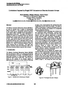
Fig. 9 Schematic view of the tugging between two interfering asperities in rolling/sliding
assumption of elastic behavior, since the plastic strain e p does not exceed 0.2%, it appears that the real contact pressure is 5% lower than the Hertz solution when considering two EP bodies. Note that the difference between the EគEP and the EPគEP solutions is given in Fig. 8 in terms of percentage as defined by Eq. 共25兲 C共%兲 =
EគEP EPគEP 兩Pmax − Pmax 兩 EPគEP Pmax
100
共25兲
From Fig. 8 it can be concluded that for L / Lc ⬍ 1, i.e., 4.5 GPa for the Hertzian pressure, the error made is less than 3%, if only one body behaves inelastically compared to two identical EP bodies in contact. It should be also noticed that, if two different elasticplastic hardening laws are considered for the bodies in contact, the difference between the EគEP and EPគEP solutions will be lowered, making more appropriate the simplification of considering the harder material as purely elastic.
4 Modeling of the Rolling/Sliding Contact Between Two (Thermal)-Elastic-Plastic Asperities Using the dd Formulation In the current incremental procedure, the normal contact is solved at every step. The geometry, the hardening state as well as the plastic strains are updated at the end of each step for each EP body. When the asperities are moving the geometry change includes the permanent deformation of the surface of the elasticplastic bodies. Special care to the effects of sliding is given since it is a more complex problem than the pure rolling situation as discussed earlier. The analysis of the contact between two asperities requires considering a relative velocity between the bearing surfaces. In addition when the tugging asperities bear only a small portion of the total load, it is clear that this transient contact will be better described by the dd formulation than by the ld one since both the subsequent localized normal and tangential loads will quickly change from zero to a maximum and then go back to zero 共meaning no contact兲. A schematic view at the beginning of the collision is shown in Fig. 9 when one of the asperities is being translated along the rolling/sliding direction relatively to the other one. For simplicity it is assumed that the center of the two colliding asperities in Fig. 9 remains in the plane 共XZ兲. 4.1 Update of the Geometry, Hardening, and Plastic Strains. The first step in transient contact calculation is to compute the static normal contact. If one of the bodies is considered elastic, then at the end of the first contact calculation, one has the situation presented on the left-hand side in Fig. 10共a兲. For the next step, the residual displacement, the hardening state and the plastic 240 / Vol. 129, APRIL 2007
Fig. 10 Updating at the end of the first loading step. „a… One of the bodies is elastic. „b… Both bodies are elastic-plastic. Case of pure rolling. „c… Both bodies are elastic-plastic. Case of rolling plus sliding contact.
strains are simply shifted from a value noted ⌬ and the new contact calculation can be processed, see right hand side in Fig. 10共a兲. As a general comment, this “updating” is only possible with the assumption that both bodies are considered as half-spaces, to be coherent with the SAM used and its limitations 共see 关7,8兴兲. If both bodies are considered elastic-plastic, the pure rolling and the rolling plus sliding situations should be differentiated. For the pure rolling case, starting from the initial configuration given on the left hand side in Fig. 10共b兲, the problem is very similar to the contact between an elastic body pressed against an elasticplastic body, except that 共i兲 the hardening state and the plastic strains are simply shifted for both bodies after each step; 共ii兲 whereas the residual displacement is doubled, as seen on the right hand side in Fig. 10共b兲. The new contact calculation can then be processed. For the 共rolling plus兲 sliding contact the situation is more complicated. Starting from the initial configuration described on the left-hand side in Fig. 10共c兲, where the hardening state and the plastic strains are simply shifted, it is clear that the residual displacement history should be considered individually for each surface, as it can be seen on the right-hand side in Fig. 10共c兲. 4.2 Calculation of the Local Interference. A global and a local reference will be considered to model the transient contact during tugging, as shown Fig. 9. The local reference 共x⬘ , z⬘兲 is linked to the plane of contact. A global interference is first applied in the global reference, by maintaining the global center separation, , along the Z direction constant during tugging. Then one of the bodies is shifted of d in the perpendicular direction 共X direcTransactions of the ASME
Fig. 13 Representation of two consecutive states i − 1 and i for the determination of i−1 Fig. 11 Displacement ␦d of body 2
⌬ ⬘ /2 i−1
tan ␣ = tion兲. As a consequence, the local center separation, ⬘, along the z⬘ direction of the local reference will be different at every step of the computation. The initial state is considered first, see Fig. 9. The global center separation is applied in the Z direction, and the two bodies are put in contact. If d0 is the initial distance between the two centers C1 and C2 in the X direction, then the local center separation ⬘ in the z⬘ direction can be expressed as a function of the global center separation , d0 and d, the latter being the sliding distance in X direction 共see Eq. 共26兲兲 and d0 the distance defined by Eq. 共27兲. In the whole development, both radii R1 and R2 are equal to R0.
⬘2 = 2 + 共d0 − d兲2 with
d20
= 共R1 + R2兲 − = 2
2
共26兲 2R20
−
2
共27兲
In this formulation, the fixed value is the shifting value ⌬ introduced in Fig. 10共a兲. As a consequence, it is required to express the sliding distance d as a function of ⌬. At any time, if one of the bodies is displaced from a value ␦d, its surface makes an angle with the shifting direction 共see Fig. 11兲. It is then possible to write
␦d = 2⌬ cos
i−1 ⬘ being the previous local center separation, ␦d can be corrected as follows � cos ␦d = 2⌬ with
� = 共⬘ /2兲␣ = 共⬘ /2兲tan−1 ⌬ i−1 i−1
共30兲
冉 冊 ⌬
⬘ /2 i−1
共31兲
Then ␦d can be re-written as follows
⬘ tan−1 ␦di−1 = i−1
冉 冊
⌬ cos i−1 ⬘ /2 i−1
共32兲
Now is determined, which is an unknown and varies with the sliding distance. Considering two consecutive states i − 1 and i 共see Fig. 13兲, one can write
⬘ i−1
cos i−1 =
共28兲
Considering the curvature of the bodies, a correction has to be � the real shifted value 共see Fig. made to the value ␦d. Denoting ⌬ 12兲, and writing that
共29兲
共33兲
Coupling Eqs. 共32兲 and 共33兲, it yields
␦di = tan−1
冉 冊 2⌬ ⬘ i−1
共34兲
The last step in the determination of the sliding distance d is the summation of all the sliding distance increments, i.e. i
di =
兺 ␦d
共35兲
k
k=1
i being the current state. The explicit form of di is then i−1
di =
兺 tan
−1
k=0
冉 冊 2⌬
⬘k
共36兲
Finally, combining Eqs. 共26兲, 共27兲, and 共36兲, the local center separation can be re-written as follows, at every step of the computation Fig. 12 Correction of the term ␦d
Journal of Tribology
0⬘ = 共R1 + R2兲 = 2R0
共37兲
APRIL 2007, Vol. 129 / 241
Fig. 15 Effect of the pile-up due to the slope of the residual displacement
Fig. 14 Projection in the global reference of the force at a point of the contact surface
i ⬎ 0:
i⬘ =
再 冋
i−1
2 + 共2R20 − 2兲1/2 −
兺 k=0
tan−1
冉 冊册 冎 2⌬
2
FX = naxay 1/2
FY = naxay
⬘k
共38兲
共40兲
Ic
FY = 0 FZ = naxay
兺 p cos
共41兲
FZ = naxay
兺 p cos共 − Ic
共43兲
py 兲
共44兲
n being the number of nodes where the contact pressure is not nil, ax and ay the grid spacings in x⬘ and y ⬘ directions, respectively 共local reference兲, and Ic the set of nodes where the pressure is not nil. As an example, Fig. 14 shows how to obtain the projected forces at a point of the contact surface. Due to the symmetry of the problem, the projected force FY on the Y axis is nil.
px兲cos共 py 兲
冉 冊 冉 冊
共45兲
with
px = tan−1
ur x
共46兲
and
py = tan−1
ur y
共47兲
⬘ 兲 sign共i⬘ − i−1
共48兲
From Eq. 共33兲, can be expressed as
= cos−1
冉 ⬘冊 i
Results. The next simulations have been inspired from the work of Vijaywargiya and Green 关18兴, who modeled the sliding contact between two cylinders using a finite element model. For the current simulations, two spherical asperities will interact. The radius of the spheres can be taken arbitrarily, so R1 = R2 = 1 m has been chosen. The elastic properties are E1 = E2 = 200 GPa for the young moduli, and 1 = 2 = 0.32 for the Poisson ratios. The chosen hardening law holds for perfect plasticity with parameter Sy = 0.9115 GPa for the yield stress. In most of the results presented, values are normalized by the critical values defined by Green in 关26兴 corresponding to the onset of yielding when plasticity just starts occurring
␣c =
冉 ⬘冊
R
共49兲
Pc =
共CSy兲3R2 6E⬘2
共50兲
Uc =
共CSy兲5R3 60E⬘4
共51兲
共42兲
Ic
242 / Vol. 129, APRIL 2007
兺 p sin共−
共39兲
Force Calculation in the Global Reference. At any time during sliding, it is possible to calculate the pressure distribution resulting from the normal contact in the local reference. As a consequence, the tangential and the normal forces in the global reference can be calculated by integrating the pressures on the X and Y axes for the tangential forces, and on the Z-axis for the normal force, i.e.
兺 p sin
px兲
Ic
4.3 Force Calculation and Results. The first part of this section deals with the force calculation that is projected in the global reference. Some correction term will be added in order to take into consideration what the authors refer as “pile-up” phenomenon. Finally, some results will be plotted concerning the tangential and normal forces found during the sliding phase, as well as the energy loss in the sliding contact, and the residual deformation after unloading at the end of the sliding process.
FX = naxay
兺 p sin共 − Ic
In order to relate the local center separation ⬘ to the interference 共rigid body approach兲 ␣ used in the semi-analytical code developed previously, one can write
␣i = 2R0 − i⬘
Correction Term Induced by the “Pile-Up”. The previous force calculation only takes into account the macro-scale projection. In order to include the effect of the pile-up, it is necessary to study the micro-scale projection. Figure 15 shows a magnified view at the point where the pressure p is applied. The residual displacement ur has a slope that makes an angle px with the x⬘ axis and py with the y ⬘ axis. From this observation, Eqs. 共40兲–共42兲 can be corrected as follows
CSy 2E
2
with ␣c the critical interference, Pc the critical load, and Uc the maximum potential energy stored during elastic deformation that Transactions of the ASME
Fig. 18 Dimensionless net energy versus dimensionless interference
Fig. 16 Dimensionless tangential force during sliding versus dimensionless sliding direction
is equal to the work done. In these equations, parameter C is expressed in function of Poisson ratio 关26兴 C共兲 = 1.30075 + 0.87825 + 0.543732
共52兲
Hereafter are plotted the reaction forces during the first sliding pass. The forces are normalized by the critical force found in Eq. 共50兲, here, Pc = 3.461⫻ 105 N, and the abscissa along the sliding direction by the equivalent radius; i.e. R = 0.5 m. Figures 16 and 17 give the tangential and the normal forces, respectively, when increasing the dimensionless interference ␣*; i.e., the interference found in Eq. 共39兲 normalized by the critical interference found in Eq. 共49兲. It can be seen in Fig. 16 that for small interference values, the tangential force is anti-symmetric, and vanishes when the asperities are perfectly aligned; i.e., for X / R = 0. On the other hand, for large values of the interference, one can see that the curve is not antisymmetric anymore. This means that most of the energy 共area under the curve兲 is produced during loading, i.e., before the asperities are aligned, and just a small part of the energy is released during unloading, i.e., when the asperities are repulsing each other. In addition the value of the force when the asperities are aligned no longer vanishes; this phenomenon is due to plastic deformation. Indeed, the residual displacement on the surface of the bodies induces some pile-up since the normal contact plane is not parallel to the sliding direction any longer. The normal force plotted in Fig. 17 is symmetric for low interference values. A slight asymmetry then begins to appear when increasing the interference; however, it is less pronounced than for the tan-
Fig. 17 Dimensionless normal force during sliding versus dimensionless sliding direction
Journal of Tribology
gential force. Again, this phenomenon is due to plasticity, since due to the permanent deformation of the surface that takes place during the first loading cycle, the normal contact plane and the sliding direction are not parallel. To give an idea of energy loss during the sliding process, Fig. 18 shows the evolution of the net energy normalized by the critical energy found in Eq. 共51兲, versus the dimensionless interference. A load ratio is now defined as FX / FZ the ratio of the tangential force over the normal one. Results are plotted in Fig. 19 versus the normalized sliding distance. It should be noted that the current simulation was made under the assumption of frictionless contact; therefore, the load ratio is only related here to the ploughing or tugging phenomena. It can be seen that for small interference values this ratio is almost perfectly antisymmetric. An increase of the load ratio is found at the beginning of the tugging 共left part of Fig. 19兲 when increasing the interference. Conversely the FX / FZ ratio tends to reach an asymptotic value of 0.045 at the end of the contact 共right part of the curves兲. In addition, it can be observed that this ratio is no longer nil when the asperities are aligned, this offset increasing with the interference value. It is again assumed to be due to plastic deformation inducing pile-up. Another interesting result is the evolution of the permanent deformation of the surface. Figure 20 shows the maximum value of the residual displacement after unloading normalized by the critical interference given in Eq. 共49兲, as a function of the interference. It shows a very significant residual deformation of the surface, up to 25% of the interference. Representative computation times corresponding to ␣* = 9, for the mesh-size dx = 3.85 mm, dy = 7.7 mm, dz = 1.925 mm 共i.e.,
Fig. 19 Load ratio during sliding versus dimensionless sliding direction
APRIL 2007, Vol. 129 / 243
⫽ step length A ← B ⫽ means that the value of B is assigned to the quantity A
Fig. 20 Dimensionless residual displacement versus dimensionless interference
33⫻ 13⫻ 31= 13,299 points兲, in the plastic zone and 25 time-step increments to describe the relative motion, took about 25 min on a 1.8 GHz Pentium® M personal computer.
5
Conclusion
For modeling an elastic-plastic rolling/sliding contact, a tridimensional elastic-plastic code has been adapted, requiring some specific developments. A new formulation has been proposed to drive the computation by imposing a normal rigid body displacement also called contact interference. Thanks to the use of optimized numerical techniques, which are the conjugate gradient and the discrete convolution and fast fourier transform, the computation time remains very reasonable in comparison to similar but 2D only analysis performed by FEM, and despite a large number of points in the plastic zone. The contact between two identical elastic-plastic bodies has been first analyzed. A significant reduction of the contact pressure compared to the situation when a purely elastic body is in contact with an elastic-plastic one has been shown. In order to complete the study, the tugging between two single asperities has then been investigated. Results have shown that plasticity produces an asymmetry of the normal and tangential loading during the transient contact. A load ratio due to ploughing has been estimated. Compared to finite element modeling, the developed code allows the user to compute a rolling and sliding contact in very short CPU times. The current work provides the foundation to incorporate electrical-mechanical interaction between rough surfaces by progressively introducing the relevant physical phenomena.
(Thermal-)Elastic-Plastic Contact Resolution ue ⫽ elastic displacement, m ut ⫽ thermal displacement, m ur ⫽ residual displacement, m h0 ⫽ initial surface separation, m p ⫽ plastic strain tensor e p ⫽ equivalent plastic strain r r 1 , 2 , r3 ⫽ principal components of the residual stress tensor, Pa PL ⫽ interpolation polynomial PLj ⫽ Lagrange polynomials C共%兲 ⫽ percentage difference between EគEP and EPគEP max pressures Lc ⫽ critical load for 0.2% equivalent plastic strain, N Elastic constants ⫽ Poisson ratio E ⫽ Young modulus, Pa E⬘ ⫽ equivalent Young modulus, Pa Geometry, Sliding Contact R1 , R2 ⫽ radii of bodies 1 and 2, respectively, m R ⫽ equivalent radius, m ⫽ global center separation, m ⬘ ⫽ local center separation, m 共X , Z兲 ⫽ global reference 共x⬘ , z⬘兲 ⫽ local reference d0 ⫽ initial distance before sliding, m d ⫽ sliding distance, m ⌬ ⫽ shifting distance, m � ⌬ ⫽ corrected shifting distance, m ⫽ angle of the plane of contact, rad FX , FY , FZ ⫽ tangential loads and normal load, respectively, N FX / FZ ⫽ load ratio px , py ⫽ pile-up angles, rad Sy ⫽ yield strength, Pa ␣c ⫽ critical interference, m Pc ⫽ critical load, N Uc ⫽ critical potential 共strain兲 energy, N m C共兲 ⫽ critical yield stress coefficient U ⫽ potential 共strain兲 energy, N m
Acknowledgment Partial support by the Rhône-Alpes Région through an Eurodoc grant for M. V. Boucly is gratefully acknowledged.
Nomenclature Elastic Contact Resolution (CGM) u ⫽ normal displacement, m p ⫽ pressure, Pa h ⫽ surface separation, m ␣ ⫽ interference, m g ⫽ gap, m P0 ⫽ initial load, N P ⫽ load, N Sg ⫽ grid area Ig ⫽ set of nodes in the grid Ic ⫽ set of grid nodes in contact Iol ⫽ set of grid nodes where there is no contact and where the surfaces overlap t ⫽ direction of the gradient r ⫽ residual 244 / Vol. 129, APRIL 2007
References 关1兴 Polonsky, I. A., and Keer, L. M., 1999, “A Numerical Method for Solving Rough Contact Problems Based on the Multi-Level Multi-Summation and Conjugate Gradient Techniques,” Wear, 231, pp. 206–219. 关2兴 Lubrecht, A. A., and Ioannides, E., 1991, “A Fast Solution of the Dry Contact Problem and the Associated Sub-Surface Stress Field, Using Multilevel Techniques,” ASME J. Tribol., 113, pp. 128–133. 关3兴 Ju, Y., and Farris, T. N., 1996, “Spectral Analysis of Two-Dimensional Contact Problems,” ASME J. Tribol., 118, pp. 320–328. 关4兴 Nogi, T., and Kato, T., 1997, “Influence of a Hard Surface Layer on the Limit of Elastic Contact—Part I: Analysis Using a Real Surface Model,” ASME J. Tribol., 119, pp. 493–500. 关5兴 Liu, S., Wang, Q., and Liu, G., 2000, “A Versatile Method of Discrete Convolution and FFT 共DC-FFT兲 for Contact Analyses,” Wear, 243, pp. 101–111. 关6兴 Liu, S., and Wang, Q., 2001, “A Three-Dimensional Thermomechanical Model of Contact between Nonconforming Rough Surfaces,” ASME J. Tribol., 123, pp. 17–26. 关7兴 Jacq, C., Nélias, D., Lormand, G., and Girodin, D., 2002, “Development of a Three-Dimensional Semi-Analytical Elastic-Plastic Contact Code,” ASME J. Tribol., 124, pp. 653–667. 关8兴 Boucly, V., Nélias, D., Liu, S., Wang, Q. J., and Keer, L. M., 2005, “Contact Analyses for Bodies with Frictional Heating and Plastic Behavior,” ASME J. Tribol., 127, pp. 355–364. 关9兴 Antaluca, E., Nélias, D., and Cretu, S., 2004, “A Three-Dimensional Model for Elastic-Plastic Contact With Tangential Loading—Application to a Dented
Transactions of the ASME
关10兴 关11兴 关12兴 关13兴 关14兴 关15兴 关16兴 关17兴 关18兴
Surface,” Proc. of the 2004 STLE/ASME Tribology Conference, Long Beach, California, October 24–27, 2004, Paper No. TRIB2004-64331. Jacq, C., Lormand, G., Nélias, D., Girodin, D., and Vincent, A., 2003, “On the Influence of Residual Stresses in Determining the Micro-Yield Stress Profile in a Nitrided Steel by Nano-Indentation,” Mater. Sci. Eng., A, 342, pp. 311–319. Sainsot, P., Jacq, C., and Nélias, D., 2002, “A Numerical Model for Elastoplastic Rough Contact,” Comput. Model. Eng. Sci., 3共4兲, pp. 497–506. Gallego, L., Nélias, D., and Jacq, C., 2006, “A Comprehensive Method to Predict Wear and to Define the Optimum Geometry of Fretting Surfaces,” ASME J. Tribol., 128, pp. 476–485. Nélias, D., Boucly, V., and Brunet, M., 2006, “Elastic-Plastic Contact between Rough Surfaces: Proposal for a Wear or Running-in Model,” ASME J. Tribol., 128, pp. 236–244. Wang, F., and Keer, L. M., 2005, “Numerical Simulation for Three Dimensional Elastic-Plastic Contact with Hardening Behavior,” ASME J. Tribol., 127, pp. 494–502. Popescu, G., Morales-Espejel, G. E., Wemekamp, B., and Gabelli, A., 2006, “An Engineering Model for Three-Dimensional Elastic-Plastic Rolling Contact Analyses,” Tribol. Trans., 49, pp. 387–399. Popescu, G., Gabelli, A., Morales-Espejel, G. E., and Wemekamp, B., 2006, “Micro-Plastic Material Model and Residual Fields in Rolling Contact,” J. ASTM Int., 3, pp. 1–12. Chen, J., Akyuz, U., Xu, L., and Pidaparti, R. M. V., 1998, “Stress Analysis of the Human Temporomandibular Joint,” Med. Eng. Phys., 20共8兲, pp. 565–572. Vijaywargiya, R., and Green, I., 2006, “A Finite Element Study of the Defor-
Journal of Tribology
关19兴 关20兴 关21兴 关22兴 关23兴 关24兴 关25兴
关26兴
mation, Forces, Stress Formation, and Energy Loss in Sliding Cylindrical Contacts,” Proc. of IJTC2006, STLE-ASME Int. Joint Trib. Conf., San Antonio, TX, October 22–25, 2006, Preprint IJTC2006-12020. Hamilton, G. M., and Goodman, L. E., 1966, “The Stress Field Created by a Circular Sliding Contact,” ASME J. Appl. Mech., 33, pp. 371–376. Hamilton, G. M., 1983, “Explicit Equations for the Stresses beneath a Sliding Spherical Contact,” Proc. Inst. Mech. Eng., Part C: Mech. Eng. Sci., 197, pp. 53–59. Kogut, L., and Etsion, I., 2003, “A Semi-Analytical Solution for Sliding Inception of a Spherical Contact,” ASME J. Tribol., 125, pp. 99–506. Faulkner, A., and Arnell, R. D., 2000, “Development of a Finite Element Model to Simulate the Sliding Interaction Between Two, Three-Dimensional, Elastoplastic, Hemispherical Asperities,” Wear, 242, pp. 114–122. Nosonovsky, M., and Adams, G. G., 2000, “Steady-State Frictional Sliding of Two Elastic Bodies with a Wavy Contact Interface,” ASME J. Tribol., 122, pp. 490–495. Fotiu, P. A., and Nemat-Nasser, S., 1996, “A Universal Integration Algorithm for Rate-Dependent Elastoplasticity,” Comput. Struct., 59, pp. 1173–1184. El Ghazal, H., 1999, “Etude des propriétés microstructurales et mécaniques des aciers 16NiCrMo13 cémenté et 32CrMoV13 nitruré-Application à la prévision de leur limite d’endurance en fatigue de roulement,” Ph.D. thesis, INSA Lyon, France. Green, I., 2005, “Poisson Ratio Effects and Critical Values in Spherical and Cylindrical Hertzian Contacts,” Appl. Mech. Eng., 10, pp. 451–462.
APRIL 2007, Vol. 129 / 245