James J. Zakrajsek .... Spiral Bevel Gear Fatigue Rig, etc. ... For more complex gears such as a spiral bevel gear, enhancements have been added to the crack ...
MODELING OF VIBRATION MEASUREMENTS FOR GEAR FAULT AND DAMAGE DETECTION ON AIRCRAFT
Marianne Mosher and Edward M. Huff NASA Ames Research Center Moffett Field, CA 94035-1000 James J. Zakrajsek NASA Glenn Research Center
ABSTRACT
The Intelligent Health and Safety Monitoring activity has been supported by NASA’s Computing, Information, and Communications Technology (CICT) Program for several years and includes a unique combination of basic information technology, rotorcraft, and aviation safety applications. One aspect of the program has been the evolution of a very close working relationship between researchers at Ames and Glenn Research Centers, who share flight and test-rig resources to address many challenges in developing effective damage detection and prognosis technology. At both Centers, Army contributions are also essential, for both computational- and flight-research support. This paper briefly reviews several kinds of modeling efforts that are currently underway at the two Centers.
INTRODUCTION
The detection of gear faults, and particularly their precursor damage patterns, has proven to be extremely difficult in dynamically operating aircraft. This is due to the complexity of the rotating gear system components, as well as ongoing modulations of their vibration signals during flight. Accurate and reliable detection of fault precursors in operating aircraft, therefore, depends upon understanding both the physical alterations that take place in the rotating equipment, as well as the ever-changing dynamic effects that must occur in the context of flight. Researchers at NASA Glenn and NASA Ames are addressing these interrelated technical problems of damage detection through a highly coordinated multidisciplinary program. The joint effort is designed to take advantage of the unique in-house ground-test and flightresearch capabilities at the two Centers, and provides an ongoing forum for the exchange of technical information and measurement methodology. The work at Glenn includes the development of physics-based gear models, the formulation of metrics that reflect gear
degradation, and the development of techniques for non-intrusive monitoring of gear damage propagation. Work at Ames includes the collection of vibration data under experimental flight conditions, the evaluation of nonstationarity effects in the flight environment, first-principles vibration signal simulation, flight dynamics modeling and studying its relationship to vibration signal modulation. Both Centers are active in supporting multivariate signal analysis, particularly with regard to the fusion of sensor data, such as oil debris, and the maturation of generic methods for planetary signal decomposition.
RESULTS AND DISCUSSION
STATISTICAL MODELING OF FLIGHT DATA
Using multivariate methods, the statistical properties of flight data are being analyzed specifically to understand the effects of speed, torque, fuel depletion, and other effects on the time/frequency characteristics of measured signals. Since the variance of recorded time series reflects the influences of both known and unknown deterministic processes, as well as random noise, attention is focused on computational methods for “correcting” the signals for these effects. The most commonly used method is continuous signal averaging, in either the time- or frequencydomain, but this has shown to be inadequate if not dangerously misleading for flight applications due to underlying non-stationarity dynamics. Work reported at the AHS-2000 [1] and 2001 [2] Annual Forums that examined and compared the three-dimensional responses of the AH-1 and OH-58C helicopters using Principal Components Analysis (PCA), was expanded in FY-03 to include mesh frequency power distributions [3]. This approach parsed the total power (i.e., RMS) in each principal axis, and was combined with an exploratory state-space analysis defined by instantaneous engine torque, torque derivative, and output shaft speed. The paper presented at the AHS-2003 Forum demonstrated the highly complex, non-linear nature of the vibration response surface. It also revealed that a single 2-hr. mission is, at least for the OH-58C, inadequate to capture a sufficient number of points within the state-space to model the surface. If this observation were to hold for heavier vehicles, the broad implication is that in-flight systems will need sufficient intelligence to learn (i.e., adapt to) the specifics of each specimen vehicle over time. During FY-04, the OH-58C flights discussed above are being re-flown with more stringent recording of pilot observations and the addition of GPS information. These will be compared with the earlier data, and multivariate techniques, such as factor-analysis, used to identify “hidden” or latent variables that may be inferred from the response covariance matrix. These same techniques will also be applied to legacy AH-1 data collected in FY-01, where aircraft attitudes were recorded that allow for a more comprehensive state-space analysis.
KINEMATIC MODELING FOR GEAR HEALTH METRICS
Simple measures of vibration amplitude, such as peak-to-peak and RMS, are the most elementary measures that could be used to monitor the health of machinery. In operational aircraft, however, such simple measures of amplitude are insufficient to determine the health of
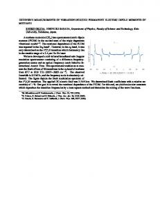
the transmission. Machinery on aircraft operates in a dynamic environment with constantly changing forces producing nonstationary vibration signals. Several gear health metrics, based upon a straightforward kinematic model of gear vibration, have been developed to detect localized damage in gears [4-6]. This kinematic model is based on the idea that the vibration produced by a healthy gear is the sum of a periodic signal containing components at the integer harmonics of the gear mesh frequency plus random noise. These characteristics assume that all gear teeth are identical and thus all gear mesh interactions are the same. To accommodate speed variation in the gear, the frequencies are based upon rotation angle instead of time. The idea is that in a gear with localized damage, the tooth-to-tooth interactions in the damaged area differ from in the undamaged area, so the vibration signal deviates from the ideal periodic signal. As an example, the FM4 metric is a measure of the kurtosis of the time synchronous averaged vibration with the gear mesh periodic components removed. Based on the assumption that the residual signal is Gaussian, the expected value is FM4=3 for an ideal gear vibration signal. With localized damage, the value of FM4 would be expected to increase, presumably due to the introduction of local phase and amplitude distortions resulting from the damage. The FM4 metric has been used extensively to test for damage in gears [5-10]. An example from NASA Glenn Research Center [11] reported the behavior of FM4 in fatigue damage tests. Figures 1a and 1b show the distribution of FM4 for regions of the tests where there was no damage, unknown damage and known damaged. Note that for the first gear in figure 1a, the distributions match the expected behavior of FM4 according to the kinematic model with very good separation between the damaged and undamaged states. In figure 1b the distributions are not so well distinguished. Distributions of the FM4 metric from a gear in a good transmission measured from flight are shown in figures 2a and 2b. Measurements from different flight conditions are shown in each curve in figure 2a and measurements from different accelerometers are shown in separate curves in figure 2b. The distributions from undamaged transmissions in flight under conditions labeled B and C in figure 2a and from accelerometer number three in figure 2b are resemble the distributions measured from a damaged gear as well as damaged gear in a ground based test rig in figure 1.
Figure 1 Estimated Probability Density Function of FM4 from Spur gear in NASA Glenn Research Center test rig. (from [11])
Although the model of periodic gear mesh vibration plus noise looks very much like the measurements, the model does not appear to be sufficiently accurate to use as a sole basis for distinguishing between good and damaged gears with vibration measurements.
1
10
Accel 1 Accel 2 Accel 3 Accel 4 Accel 5 Accel 6 Kinematic Model
0
Estimated PDF
10
−1
10
−2
10
−3
10
1.5
2
2.5
3
3.5
4
4.5
5
FM4
Figure 2 Estimated Probability Density Function of FM4 from gear in OH-58 Flight Test at NASA Ames Research Center. (2a from[11])
MULTIVARIATE SENSOR FUSION MODELS
The reliability and accuracy of detecting damage in rotating machinery is a direct function of the accuracy of the physical sensor and corresponding diagnostic techniques being used. Studies at NASA Glenn [10, 12] have shown that by integrating the signals and features from a variety of sensors, the integrated system shows improved detection and decision-making capability as compared to individual measurement methods. This is especially true for those failure modes for bearings and gears that generate both wear debris in the oil and vibration signatures when failure occurs. In this effort at Glenn Research Center, multivariate decision fusion is being used to develop diagnostic tools to accurately and reliably detect bearing and gear damage on-line. During the coming year work will be completed on a general purpose diagnostic software tool and evaluated experimentally with gear/bearing vibration and oil debris data from NASA Glenn Test rigs, e.g., the 500-HP Helicopter Transmission Test Facility, Spur Gear Fatigue Rig, Spiral Bevel Gear Fatigue Rig, etc. Multivariate decision fusion schemes are also being incorporated for planetary fault detection using vibration, oil debris, and acoustic emission data from test rigs and transport aircraft as they become available.
NUMERICAL MODELING OF CRACK PROPAGATION
Cracks that develop in gears are a very important category of mechanical failure. Unlike those that occur within individual gear tooth, fractures that expand through the gear rim may lead to the catastrophic loss of the transmission or engine, and seriously compromise aircraft safety.
Predicting crack propagation in gears by means of numerical modeling is a recent development [13, 14]. Knowledge gained through numerical modeling can be used to design gears with less catastrophic failures modes, help with prognostic estimates of useful gear life and gain insight for developing fault detection methods. Crack propagation modeling in gears involves multiple methods combined together. The general steps are 1) define the geometry of the gears, 2) generate a grid, 3) determine the contact path, 4) initiate the crack, 5) remesh around the crack, 6) solve structural equations 7) propagate crack and continue to loop through steps 5 to 7 until some end point is reached. The simplest modeling is done with 2-dimentional finite elements and has been used to study crack propagation in spur gears. At NASA Glenn, Lewicki [13, 15, 16] used this method successfully within the framework of linear elastic fracture mechanics to study the effects of rim thickness, initial crack location, and rotational speed of crack propagation Gear tooth coordinates were modeled based upon the method of Hefeng [17] and the tooth load was placed at the highest point of single tooth contact. This finite element modeling method utilized eight-node quadrilateral and six-node triangular elements, as show in Figure 3. In the vicinity of the crack, six-node elements were used to model the inverse square-root stress singularity. After each step of the structural equation solver, the stress intensity factors were calculated and used to determine the extent and direction of crack propagation. In order to validate the method, the predicted crack propagation path was compared with the results of experiments also conducted at Glenn Research Center. Figure 4 shows both the prediction and measurements from spur gears with three different rim thicknesses. It is notable that the location of the physical crack closely follows the predicted crack in all three cases; of particular interest is the agreement of prediction with experiment with regard to the location and direction of the crack through the tooth or through the rim.
Quarterpoint rosette
Crack tip
(a)
Simulated crack trajectory
(b)
Initial crack region
(c)
Figure 3 Grids from 2-D finite element crack propagation. (from [15])
Figure 4 Comparison of predicted crack propagation with experiment (from [15])
For more complex gears such as a spiral bevel gear, enhancements have been added to the crack propagation modeling. Moving tooth loads through modeling are included in some studies [16, 18, 19]. Boundary element [14, 18] and 3-dimentional finite element [20, 21] models have been used for the structural equations.
FIRST PRINCIPLES MODELING OF DAMAGE
To identify the unique vibration characteristics of a specimen gear system, the most comprehensive approach is to compare vibration output with that of a physics-based computational model that represents what a perfect gear system would produce under ideal operating conditions. This is being pursued by first-principles, finite-difference modeling of the gear component geometries under rotation by solving the three-dimensional elastodynamic partial differential equations with the appropriate dynamic boundary conditions. Numerical simulations of stresses over component geometries that define an overall geometry for gear teeth in mesh for rotating systems such as helicopters are being carried out using first-principles modeling approach. Using this technique, it is anticipated that nominal “reference” vibration signatures will shortly become available. Following that, “ideal” damage signatures will be produced for various problems of interest. Since extremely intensive computing is required, however, NASA Advanced Supercomputing facilities at Ames Research Center will most probably be required. A new three-dimensional elliptic grid generation methodology has been developed that is based on new boundary constraints for elliptic grid generation boundary-value problems [22], thus making it possible to generate gear grids during simulation without user intervention. Figure 5 shows a 2-dimentional section of an automatically generated grid for a gear. Since the new elliptic grid generation methodology makes it possible to generate the grids automatically [23], it will make finite difference solution of structural dynamics problems a viable technology to simulate gear teeth crack propagation in time, as well as to simulate other asymmetric time-dependent gear fault phenomena involving gear grids where individual teeth are subject to deformation, wear, pitting, etc. As an example of the system’s capabilities, Figure 6 shows a comparison between the analytical (blue) and the computed (red) normalized radial stress and tangential stress distributions, respectively, for an annulus gear along any radial ray over the full length of the diameter. The abscissa denotes the radial index of the grid points along the diameter, from one end to the other, and the ordinate the corresponding stress. This case corresponds to a rotational
speed of 2,000 revolutions per second, with an integration time step of 40 nanoseconds. The results shown are attained after 6.4 revolutions, when the system has not yet attained a steady state [24]. The implementation of boundary conditions for this test case was made possible by deriving them from the corresponding analytical solutions. But, for gears in mesh, general hyperbolic boundary conditions have to be derived to make the corresponding predictions. Papers involving this work are being prepared for forum presentations and appropriate journals.
Figure 5 Section of gear grid automatically generated (from [22])
Figure 6 Comparison of analytic and finite difference for 2-dimentional spinning annulus.
A Structural Dynamics Simulator and Animator (SDSA) have been developed and are presently being improved with regard to prediction accuracy. In particular, work is being carried out on the boundary condition formulation based on the theory of hyperbolic systems. Work is also ongoing to improve the usefulness of the animation capability, which now not only displays the predictions graphically in simulation tine, but also can also be interrupted and checked for anomalies either in the grids or the physical quantities that are displayed. The evolving grids can now be inspected in three-dimensional space by rotating, zooming or translating them on the screen, at any point during the simulation.
SUMMARY AND CONCLUSIONS
The modeling work summarized above represents the combined, multidisciplinary capabilities of researchers at Ames and Glenn Research Centers who are focused on developing
effective damage detection methods for real-time aerospace applications. The program has made several major breakthroughs in computational science. These include unique information processing hardware-software modules now being used in test rigs as well as research aircraft. Much more importantly, however, they include insights from several scientific modeling efforts that serve to clarify the limitations of present commercial Health and Usage Monitoring (HUMS) techniques. Overall, the results point the way to the development of needed information technology for future in-flight use. On the whole, what has been learned is that successful damage detection methods must account for the dynamical influences of real-time vehicle operations, which result in nonstationary signals and highly nonlinear signal response surfaces. Attacking this broad problem is unmistakably one of the most demanding technical challenges for computational sciences research in the vehicle health-monitoring arena. Success, no doubt, will depend upon maintaining a focused interdisciplinary research capability that spans classical statistics, signal analysis, data fusion, control theory, and computer architecture.
ACKNOWLEDGMENTS
The authors would like to thank the Management of NASA’s Computing, Information, and Communications Technology (CICT) Program, for providing the ongoing support for this effort. We would also like to complement the Army Flight Projects Office (FPO) for the coordination of all aircraft instrumentation and operations. Special thanks is also due for California Signal Processing (Sigpro), for outstanding flight research support.
REFERENCES
1. 2. 3. 4. 5.
6. 7. 8.
Huff, E.M., et al., Experimental analysis of Steady-State Maneuvering Effects on Transmission Vibration Patterns Recorded in an AH-1 Cobra Helicopter, in 56th Annual Forum. 2000, American Helicopter Society: Virginia Beach, VA. Huff, E.M., I.Y. Tumer, and M. Mosher. An Experimental Comparison of Transmission Vibration Responses from OH-58 and AH-1 Helicopters. in American Helicopter Society 57th Annual Forum. 2001. Washington D.C.: American Helicopter Society. Huff, E.M., M. Mosher, and E. Barszcz. An Exploration of Discontinuous Time Synchronous Averaging Using Helicopter Flight Vibration Data. in American Helicopter Society 59th Annual Forum,. 2003. Phoenix, AZ: American Helicopter Society. Stewart, R.M., Some useful Data Analysis Techniques for Gearbox Diagnostics. 1977, University of Southampton: Southampton, England. Zakrajsek, J.J., D.P. Towsend, and H. Decker. An Analysis of Gear Fault Detection Methods as Applied to Pitting Fatigue Failure Data. in 47th Meeting of Society for Machinery Failure Prevention Technology. 1993: Society for Machinery Failure Prevention Technology. Choy, F.K., et al., Vibration signature Analysis of a Faulted Gear Transmission System, in 30th Joint Propulsion Conference. 1994, AIAA: Indianapolis, Indiana. Zakrajsek, J.J., et al. Detecting Gear Tooth Fractures in a High Contact Ratio Face Gear Mesh. in 49th Meeting of the Society for Machinery Failure Prevention Technology. 1995. Virginia Beach, VA: Society for Machinery Failure Prevention Technology. McClintic, K., et al. Residual and Difference Feature Analysis with Transitional Gearbox Data. in 54th Meeting of the Society for Machinery Failure Prevention Technology. 2000: Society for Machinery Failure Prevention Technology.
9. 10. 11. 12. 13. 14. 15. 16. 17. 18. 19. 20. 21. 22. 23. 24.
Campebell, R.L., C.S. Byingtom, and M.S. Lebold. Generation of HUMS Diagnostic Estimates Using Transitional Data. in 13th International Congress and Exhibition on Condition Monitoring and Diagnostic Engineering Management. 2000. Dempsey, P.J., A Comparison of Vibration and Oil Debris Gear Damage Detection Methods Applied to Pitting Damage. 2000, NASA Glenn Research Center. Dempsey, P.J., M. Mosher, and E.M. Huff. Threshold Assessment of Gear Diagnostic Tools on Flight and Test Rig Data. in American Helicopter Society 59th Annual Forum. 2003. Phoenix, AZ: American Helicopter Society. Dempsey, P.J., R.F. Handschuh, and A.A. Afjeh, Spiral Bevel Gear Damage Detection Using Decision Fusion Analysis. 2002, NASA Glenn Research Center: Cleveland OH. Lewicki, D.G. and R. Ballarini, Effect of Rim thickness on Gear Crack Propagation Path. 1996, American Society of Mechanical Engineers: San Diego, California. Lewicki, D.G., et al., Three-Dimensional Gear Crack Propagation Studies. 1998, NASA Glenn Research Center: Cleveland, OH. Lewicki, D.G., Gear Crack Propagation Path Studies - Guidelines for Ultra-Safe Design. 2001, U.S. Army Research Laboratory: Cleveland, OH. Lewicki, D.G., Effect of Speed (Centrifugal Load) on Gear Crack Propagation Direction. 2001, U.S. Army Research Laboratory: Cleveland, OH. Hefeng, B., M. Savage, and R.J. Knorr, Computer Modeling of Rack-Generated Spur Gears. Mechanism and Machine Theory, 1985. 20(4): p. 351-360. Lewicki, D.G., et al. Consideration of Moving Tooth Load in Gear crack propagation Predictions. in 8th International Power Transmission and Gearing Conference. 2000. Baltimore, Maryland: American Society of Mechanical Engineers. Speivak, L.E., et al., Simulating Fatigue Crack Growth in Spiral Bevel Gears. Engineering Fracture Mechanics, 2001. 68: p. 53-76. Ural, A., P.A. Wawrzynek, and A.R. Ingraffea, Simulating Fatigue Crack Growth in Spiral Bevel Pinion. 2003, Cornell University: Ithaca, NY. Ural, A., et al., Simulating Fatigue Crack Growth in Spiral Bevel Gears using Computational Fracture Mechanics. 2003, ASME: Chicago, IL. Kaul, U.K., New Boundary Constraints for Elliptic Systems used in Grid Generation Problems. Journal of Computation Physics, 2003. 189: p. 476-492. Kaul, U.K. and E.M. Huff, Elliptic Grid Generation of Spiral-Bevel Pinion Gear Typical of OH-58 Helicopter Transmission. 2002, NASA Ames Research Center: Moffett Field, CA. Kaul, U.K., FiDSED: A Computer Code for Finite Difference Simulation of Elastodynamic Phenomena in Generalized Curvilinear Coordinates. 2004, NASA Ames Research Center: Moffett Field, CA.