However, subsurface drainage in a paddy field is quite different from ... paddy field for various drain depths (0.5, 0.75 and 1.0 m) and spacings (7.5 and 15.0 m), ...
Modeling paddy field subsurface drainage using HYDRUS-2D Abstract All of steady and non-steady subsurface drainage equations were developed mostly based on water flow pattern in an ordinary field conditions. However, subsurface drainage in a paddy field is quite different from
"
subsurface drainage in an ordinary field. Thus, it is necessary to develop new equations and mathematical
$
models to design subsurface drainage system in a paddy field. The objective of this study was to apply the
,
HYDRUS-2D model, based on the Richard’s equation, to simulate water flow under subsurface drainage in a
4
paddy field for various drain depths (0.5, 0.75 and 1.0 m) and spacings (7.5 and 15.0 m), surface soil textures
6
(clay loam and silty clay loam) and crack conditions. Simulation results were compared with two well-known
8
drainage equations. The maximum drainage rate was obtained under 7.5 m spacings and 1 m depth. With increasing drain spacings, the drainage rate decreased. Drain spacings had more effect on drainage rate and water pressure head as compared to drain depth. Drainage rates calculated by the Hooghoudt’s and Murashima and Ogino’s equations were much lower than those calculated by the Richard’s equation. The Hooghoudt’s equation, developed for ordinary fields, did not perform well for paddy fields. This study also
"
proved the importance of cracks in subsurface drainage system of paddy fields. HYDRUS-2D stands as a
$
robust tool for designing subsurface drainage in a paddy field.
,
Key words: Crack, Drainage rate, Model, Paddy field, Subsurface drainage.
4 6
1
8
Introduction Rice is one of major food crop in Iran. Agriculture of northern Iran is characterized by rice production because of humid climate and much rainfall. In paddy fields where the surface soil is heavy (e.g. clay), subsurface drainage is necessary in addition to surface drainage. Drainage improvement of the paddy fields is required for mechanization (Tabuchi 2004). Heavy machinery such as combine harvesters is difficult to
"
operate on poorly-drained clayey paddy fields when rainfall occurs during the harvesting period in late
$
summer and autumn. In this condition, labor efficiency is too low and combine harvesters and tractors could
,
not move easily due to the low bearing capacity of the soil. Rapid drainage is necessary in order to dry the
4
field before the harvest. Producing non-rice crops such as canola after rice harvest for second growing season
6
in the paddy fields has an important role in farmer income and food production. It necessitate drainage need
8
more through reinforced surface drainage to protect the crops from flooding and through subsurface drainage to solve the problem of rotting roots and stunted growth of non-rice crops (Ogino and Ota 2007). The purpose of subsurface drainage in a paddy field is to remove the excess water in the surface soil and remaining water on the soil surface (Ogino and Ota 2007). Subsurface drainage in a paddy field with a hard pan is different from subsurface drainage in an ordinary field. For planning and design of subsurface drainage
"
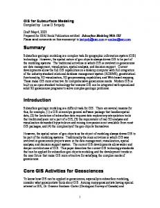
in paddy fields, understanding of water flow pattern towards drainage pipe is necessary. Fig. 1 shows the
$
water flow pattern in subsurface drainage of ordinary and paddy fields. In ordinary fields, water flowing
,
towards a drain pipe is in the vertical, horizontal and radial directions. The latter direction is usually dominant
4
in subsurface drainage of these fields. However, field and soil characteristics have specific effects on drainage
6
flow pattern in paddy fields. Two layers characterize a typical soil profile of a paddy rice field. The surface
8
ploughed soil layer is located 20–30 cm in depth and is highly permeable. Second layer, called as a hard pan, is the non-ploughed subsoil and is impermeable. The hard pan is developed just below the surface soil layer, between the two soil layers, by puddling to prepare transplanting. The hard pan facilitates holding water on the surface soil and prevents a well-drained condition (Ogino and Ota 2007). Understanding of soil hydraulic conductivity of paddy fields is important in paddy fields sub-drainage. The soil hydraulic conductivity and
"
water flows towards sub-drains in paddy fields depend on cracking degree due to drying of the surface soil. It
$
also takes several years to dry and crack the impermeable subsoil and therefore the backfilled trench (Fig. 1)
,
and its hydraulic conductivity is very important for water flows into sub-drains (Tabuchi 2004). In whole,
4
water flows horizontally through cracks in the surface soil and then vertically into the sub-drains through the
6
backfilled trench (Fig. 1).
"8
Tabuchi (2004) stated that subsurface drainage for a clayey paddy field is completely different from
"
subsurface drainage for an ordinary field. He recommended field and soil characteristics, as well as water
"
conditions, should be examined carefully before planning drainage improvement for farm mechanization.
"
Ogino and Ota (2007) described the evolution of rice field drainage in Japan focusing on the last 60 years.
"
They established a steady state method for calculating drain spacing in paddy fields by considering water flow
""
pattern in paddy fields. They also introduced some technical criteria in terms of drainage system layout,
"$
structure of subsurface drainage and design drainage rate. Japanese advisors had carried out the subsurface
2
",
drainage in a one-hectare paddy field using rice husk as envelope in Mazandaran, a northern province of Iran
"4
for the first time in 1994 (Ebrahimian et al. 2011). The performance of subsurface drainage with rice husk
"6
envelope in the studied paddy field was satisfactory. Subsurface drainage in this province is known as a
$8
necessary practice for producing non-rice crops as well as increasing rice yield. Darzi-Naftchally et al. (2013)
$
evaluated steady state and unsteady state drainage equations to compute drain spacing in paddy fields. The
$
computed drain spacings were evaluated using dynamic equilibrium concept and DRAINMOD model.
$
Unsteady-state equations were found to be more suitable than those obtained from the steady-state equations
$
because of highly variable rainfall in the studied paddy fields. They assumed that the water flow pattern in a
$"
paddy field is the same as in an ordinary field.
$$
All of steady and non-steady subsurface drainage equations were developed mostly based on water flow
$,
pattern in ordinary field conditions. Drainage simulation models such as DRAINMOD (Skaggs 1980) and
$4
SWAP (Kroes and Van Dam 2003) were also developed based on such conditions. Therefore, it is necessary
$6
to develop more equations, particularly for unsteady state, to calculate drain spacings and mathematical
,8
models to simulate water flow pattern of subsurface drainage in paddy fields.
,
The HYDRUS model (Simunek et al. 1999) has been successfully applied in various issues of irrigation and
,
drainage such as simulating water flow and solute transport in furrow irrigation (Crevoisier et al. 2008;
,
Ebrahimian et al. 2013), wetted soil volume in surface and subsurface drip irrigation (Provenzano 2007;
,
Monjezi et al. 2013), subsurface drain discharge rates and chemical concentrations in the drainage water
,"
(Boivin et al. 2006) and salt and water movement in soil under rice crop irrigated with different water salinity
,$
(Phogat et al. 2010).
,,
In this study, we focus on the simulation of water flow pattern towards drainage pipe in paddy fields and
,4
propose to use the two dimensional HYDRUS model (HYDRUS-2D) as a physically based continuous model
,6
developed to simulate water movement in complicated conditions. The HYDRUS-2D model was run for
48
various conditions to investigate impact of surface soil texture, drain depth and spacing and crack conditions
4
on drainage rate and water pressure head above the hard pan. Simulation results are also discussed and
4
compared with two well-known drainage equations.
4 4 4" 4$ 4, 44 46
3
68
Materials and methods
6
Hooghoudt’s equation
6
One of the well-known drainage equations for calculating drain spacing is Hooghoudt (1940) equation:
6
L2 =
6
where ht (m) is the head of water midway between drains, Ka and Kb (m day-1) are the soil hydraulic
6"
conductivity of above and below drain level, respectively, q (m day-1) is the design drainage rate, L (m) is the
6$
drain spacings and d (m) is the Hooghoudt’s equivalent depth.
6,
The Hooghoudt’s equation is based on the radial flow assumption in the region near the drains and the
64
Dupuit-Forchheimer assumptions in the region away from the drains. This equation is applied for parallel
66
subsurface drainage systems (Fig 1. a) under steady state condition.
88
If the drain pipe is installed on the impermeable soil layer, Eq. 1 can be written as follows:
8
L2 =
8
Murashima and Ogino’s equation
8
The flow pattern in a narrow surface soil layer above hard pan in paddy fields is almost horizontal.
8
Murashima and Ogino (1992), using the parallel flow assumption, introduced the following empirical drain
8"
spacings formula (as a steady state method) for design of subsurface drainage in Japan:
8$
L = 2H (
8,
where H (m) is the surface soil thickness and K (m day-1) is the hydraulic conductivity of the surface soil. In
84
this equation, it is assumed that only the surface soil is permeable and the backfilled trench zone has no
86
impedance for the flow. The surface soil thickness is usually in the range of 20–30 cm in the northern part of
2
8
4 K a ht 8 K dh + b t q q
4 K a ht q
(1)
2
(2)
K 0.5 ) q
(3)
Iran. The hydraulic conductivity of cracked or well-structured clayey soil is often much higher than that of sandy soils (Ogino and Ota 2007). It is difficult to obtain a correct value of the hydraulic conductivity of thin surface soil by using the auger hole method. Murashima and Ogino (1985) recommended the actual value of K can be estimated by modifying a measured hydraulic conductivity, Ks, through field tests as follows:
4
"
K = cK s
$
where c (-) is the modification coefficient and Ks (m day-1) is measured hydraulic conductivity. The
,
modification coefficient is usually ranged from 10-1000.
(4)
4 6
HYDRUS-2D
8
The HYDRUS-2D Version 2.0 model (ŠimOnek et al. 1999) was used in this study. This model employs two dimensional form of the Richards' equation for simulating water flow in variably saturated porous media:
t
=
where
xi
h + K iz ) xj
K ( K ij
S
(5)
[-] is the volumetric water content, h [L] is the pressure head, S [T-1] is a sink term, xi and xj [L] are
the spatial coordinates, t [T] is time, KijA are components of a dimensionless anisotropy tensor KA and K [L T-
"
1
$
The HYDRUS-2D model implements the soil-hydraulic functions proposed by van Genuchten (1980) and
,
Mualem (1976) to describe the soil water retention curve,
4
function, K(h), respectively:
6
] is the unsaturated hydraulic conductivity function. In this study, S was assumed to be zero.
(h) =
r
+
s
[1 +
h
r n m
]
s
8
l
[
K (h) = K s S e 1 (1 S e
(h), and the unsaturated hydraulic conductivity
h 1
(8)
Se =
(9)
r s
where
r
r
[-] and
s [-]
denote the residual and saturated water content, respectively; V [L-1] is the inverse of
the air-entry value; Ks [L T-1] is the saturated hydraulic conductivity, n [-] is the pore-size distribution index,
"
Se [-] is the effective water content; and l [-] is the pore-connectivity parameter with an estimated value of
$
0.5, resulting from averaging conditions in a range of soils (Mualem 1976).
5
,
The model inputs for simulating water flow included soil hydraulic parameters, soil layers, flow domain
4
geometry and initial and boundary conditions. In this study, the soil hydraulic parameters were estimated
6
using the Neural Network approach provided by HYDRUS-2D regarding the soil texture. Geometry and
8
boundary conditions for defining the physical problem of this study are shown in Fig. 2. A water stagnant layer above soil surface in paddy fields (about 5-10 cm) is usually provided by farmers through rainfall or irrigation water. But the water stagnant head reduces with time when starting drainage practice. Thus, the condition of variable pressure head is existed above soil surface during the drainage. For this reason, a variable pressure head was specified as the boundary condition for the soil surface. However, for the
"
Hooghoudt equation, the water influx in the soil surface is assumed a constant rate and drained steadily. In
$
fact, HYDRUS-2D simulates subsurface drainage under non- steady state condition. No–flux boundary
,
conditions were applied to the sides of the flow domain. A seepage face was specified as the boundary
4
condition for the drain. Saturated soil water content within the flow domain and 5 cm water head above soil
6
surface (as initial pressure head) were used as initial conditions.
"8
Typical surface soil textures of paddy fields of the northern part of Iran, clay loam and silty clay loam were
"
chosen for model simulations. Subsurface drain depth is usually shallower than 1 m because of depth
"
restrictions of collector surface drains in the paddy fields consolidation. Therefore, three depths for subsurface
"
drains (0.5, 0.75 and 1 m) were investigated in this study. The standard plot size of a paddy field in Iran is 0.3
"
ha, 100 m long and 30 m wide, similar to Japan’s paddy fields. Each plot has a farm road with a farm
""
irrigation ditch along one of the shorter 30 m sides and a farm drain ditch along the other shorter side. In
"$
Japan, the most common subsurface drainage spacings are 7.5, 10 and 15 m (Oginio and Ota 2007). In this
",
study, two drainage spacings, 7.5 and 15 m, were investigated. The hard pan depth, trench width and drain
"4
diameter were considered to be 0.30, 0.25 and 0.10 m, respectively. Sand soil was chosen as drainage
"6
envelope. The trench was assumed to be backfilled with the sand soil and covered with surface soil. The soil
$8
hydraulic parameters used for model simulations are presented in Table 1. The model was run for 7 days.
$
Drainage rate and water head above hard pan were simulated for each condition with respect to surface soil
$
texture and drain depth and spacings.
$
The HYDRUS model could not consider crack effect in surface soil. However, cracks have a key role in
$
subsurface drainage (Tabuchi 2004). For this reason, the modification coefficient (c=10) for surface soil
$"
hydraulic conductivity was also taken into account. In fact, the simulations were carried out for with- and
$$
without-crack conditions.
$, $4 $6
Results and discussions 6
,8
Drainage rate
,
Hydrographs of drainage rate with respect to time for different subsurface drainage spacings and depth and
,
surface soil texture conditions calculated by HYDRUS-2D are presented in Fig. 3. There was sudden drop of
,
drainage rate after passing one day for all cases. High drainage rate in initial times is related to rapid discharge
,
of water above drain pipe due to gravity force. After draining this part, drainage rate suddenly decreased
,"
because horizontal water velocity above hard pan to reach drain trench was low. Therefore, drainage rate
,$
gradually decreased with increasing time. The maximum drainage rate was obtained under 7.5 m spacings and
,,
1 m depth for clay loam soil. The deeper drain depth, the more drainage rate. With increasing drain spacings,
,4
the drainage rate decreased. In fact, there was an inverse relationship between drainage rate and drain
,6
spacings. Drain spacings had somewhat more effect on drainage rate as compared to drain depth. As expected,
48
water could flow through the topsoil in clay loam easier than in silty clay loam.
4
Cumulative drainage for different subsurface drainage spacings and depth and surface soil texture conditions
4
calculated by HYDRUS-2D is presented in Fig. 4. Cumulative drainage highly depends on both drain depth
4
and spacings. It ranged from 5.3 to 12.7 mm for clay loam and 2.8 to 9.4 mm for silty clay loam.
4
Interestingly, the type of soil texture determines the impact of drain depth and spacings on cumulative
4"
drainage. Drain depth and spacing had more effect on cumulative drainage in silty clay loam and clay loam,
4$
respectively. Cumulative drainage increased with decreasing drain spacing and increasing drain depth.
4,
Therefore, the highest value of cumulative drainage was obtained for 7.5 m spacing and 1 m depth (12.7 mm
44
for clay loam and 9.4 mm for silty clay loam).
46
The values of drainage rate, calculated by the Murashima and Ogino’s equation (Eq. 3), for 7.5 and 15 m
68
drain spacing were 3.99 and 1.00 mm day-1 for clay loam soil surface and 1.08 and 0.27 mm day for silty clay
6
loam soil surface, respectively, under crack condition (c=10). HYDRUS-2D simulated much more values of
6
drainage rate relative to Eq. 3 (Fig. 3). Of course, the performance of subsurface drainage system in paddy
6
fields highly depends on soil cracking degree (i.e. modification coefficient (a) for hydraulic conductivity). It
6
is obvious that drainage rate is higher with higher degree of cracks. Under high crack condition, the
6"
Murashima and Ogino’s equation yields larger value of drainage rate.
6$
Fig. 5 shows relationship between pressure head and drain discharge for the HYDRUS-2D model (Richard’s
6,
equation) and the Hooghoudt’s equation. As seen, there is a big difference between these two equations in
64
predicting drainage rate regarding pressure head, mainly for higher pressure head condition. Drainage rates
66
calculated by the Hooghoudt’s equation were much lower than those calculated by the Richard’s equation.
88
This difference might be related to limitation of the Hooghoudt’s equation when installing drain pipe at
8
impermeable layer (Smedema et al. 2004). In addition, the Richard’s equation is a physical equation without
8
any simplified assumptions, whereas the Hooghoudt’s and Murashima and Ogino’s equations are semi-
8
physical and empirical equations, respectively. The Hooghoudt’s equation, developed for ordinary fields, did
7
8
not perform well for paddy fields. Moreover, this equation as well as the Murashima and Ogino’s equation
8"
were developed under steady state conditions. While HYDRUS-2D simulates subsurface drainage under non-
8$
steady state conditions that is very close to real conditions.
8, 84
Water head between drains
86
Time variations of water head above the hard pan midway between two drains (midpoint head) are presented
8
for all cases in Fig. 6. With passage of time, midpoint head decreased due to discharge from the drain. The wider drain spacings, the bigger midpoint head. However, the drain depth had very low effect on midpoint head. Murashima and Ogino (1992) reported that drain depth can be neglected in the consideration on drain spacing because of high permeability of the drain trench. The water head simulations also confirmed this point. However, as previously indicated, cumulative drainage and drainage rate were function of drain depth.
"
Because of heavy surface soil and no cracks, the drainage system was not able to reduce the midpoint head
$
beyond 12 and 15 cm for clay loam and silty clay loam, respectively, for 15 m drain spacings. However, these
,
values were 21 and 25 cm for clay loam and silty clay loam, respectively, for 7.5 m drain spacings. With
4
crack consideration, the drainage system could considerably reduce midpoint head even to negative values of
6
midpoint head for 7.5 m drain spacings. Negative value of midpoint head is so important for harvest period of
8
rice and producing non-rice crops in paddy fields. After one weak, the midpoint head was equal to 6 and 10 cm for clay loam and silty clay loam, respectively, for 15 m drain spacings. In fact, crack was the reason for increasing discharge from the drain. These results proved crack importance in subsurface drainage system of paddy fields. Tabuchi (2004) also stated that water movement in clayey soil depends on whether or not it has cracks. Thus, it is necessary to change the impermeable clayey soil into dry soil with cracks to remove the
"
excess water in the surface soil and remaining on the soil surface.
$
Temporal and spatial variation of water head above the hard pan between two drains a presented in Fig. 7.
,
There was a big difference between head above drain trench (h0) and midpoint head (hL/2). But, there was a
4
low difference between midpoint head and head at one-quarter spacing from drain (hL/4). As mentioned
6
previously, water head above drain trench suddenly decreased owing to rapid discharge of water resulting
8
from gravity force and high permeable drain trench. For this reason, water pressure head above drain trench became negative.
Conclusions
8
In this study, the two dimensional simulation model, HYDRUS-2D, was applied to simulate water flow under
"
subsurface drainage condition in a paddy field. The geometry and boundary conditions were defined based on
$
trench-type subsurface drainage in a paddy field that is completely different from subsurface drainage in an
,
ordinary field. Effect of drain depth and spacings, surface soil texture and crack condition on drainage rate,
4
cumulative drainage and water pressure head above hard pan were investigated in this simulation study.
6
Unlike drain depth, drain spacing considerably affect on water pressure head. Water could flow through the
8
topsoil in clay loam easier than in silty clay loam resulting more drainage rate and lower pressure head. The performance of subsurface drainage system in paddy fields highly depends on the degree of topsoil cracking. Therefore, measurement of the hydraulic conductivity of cracked topsoil is most important. HYDRUS-2D, the Richard’s equation, simulated much more values of drainage rate relative to the Hooghoudt’s and Murashima and Ogino’s equation. The Hooghoudt’s equation, developed for ordinary fields, did not perform well for
"
paddy fields. Moreover, this equation as well as the Murashima and Ogino’s equation were developed under
$
steady state condition. While HYDRUS-2D simulates subsurface drainage under non-steady state conditions
,
that is very close to real conditions. The potential of the HYDRUS-2D model be used in design and
4
management of subsurface drainage system in a paddy field is highlighted. The model is quite flexible to
6
define and simulate various subsurface drainage systems. While, the drainage simulation models, such as
"8
DRAINMOD and SWAP, have been designed just for ordinary fields. Besides, the HYDRUS-2D model is
"
capable to simulate chemical concentration (e.g. salt and nitrate) in drainage water and soil profile.
"
Application of this model, as an approach for alleviation of the environmental impact of subsurface drainage,
"
is recommended in the future studies.
" ""
Acknowledgment
"$
The authors declare that they have no conflict of interest.
",
References
"4
Boivin A, ŠimOnek J, Schiavon M, van Genuchten MT (2006) Comparison of pesticide transport processes in
"6 $8 $
three tile-drained field soils using HYDRUS-2D. Vadose Zone J 5(3):838-849 Crevoisier D, Popova Z, Mailhol JC, Ruelle P (2008) Assessment and simulation of water and nitrogen transfer under furrow irrigation. Agric Water Manag 95(4):354-366
$
Darzi-Naftchally A, Mirlatifi SM, Asgari A (2013) Comparison of steady-and unsteady-state drainage
$
equations for determination of subsurface drain spacing in paddy fields: a case study in Northern Iran.
$
Paddy Water Environ 1-9
$"
Ebrahimian H, Liaghat A, Parsinejad M, Playán E, Abbasi F, Navabian M (2013) Simulation of 1D surface
$$
and 2D subsurface water flow and nitrate transport in alternate and conventional furrow fertigation.
$,
Irrig Sci 31(3):310-316
9
$4
Ebrahimian H, Parsinejad M, Liaghat A, Akram M (2011) Field research on the performance of a rice husk
$6
envelope in a subsurface drainage system (case study Behshahr, Iran). Irrig Drain 60(2):216-228
,8
Hooghoudt SB (1940) General consideration of the problem of field drainage by parallel drains, ditches,
,
watercourses, and channels. Publication No.7 in the series contribution to the knowledge of some
,
physical parameters of the soil. Bodemkundig Instituut: Groningen, The Netherlands
, , ," ,$ ,, ,4 ,6 48
Kroes JG, Van Dam JC (2003) Reference Manual SWAP version 3.0.3. Wageningen, Alterra, Green World Research. Alterra-report 773 Monjezi MS, Ebrahimian H, Liaghat A, Moradi MA (2013) Soil wetting front in surface and subsurface drip irrigation for silty loam soil. ICE Water Manag 166(5):272-284 Mualem Y (1976) A new model for predicting the hydraulic conductivity of unsaturated porous media. Water Resour Res 12(3):513–522 Murashima K, Ogino Y (1985) Design of pipe drainage using the modification coefficient (a). Transactions of the Japanese Society for Irrigation, Drainage and Reclamation Engineering 119:13–20
4
Murashima K, Ogino Y (1992) Comparative study on steady and non-steady state formulae of subsurface
4
drain spacing – design on subsurface drainage of paddies (1). Bulletin of the University of Osaka
4
Prefecture Ser. B, 44: 41–48
4 4"
Ogino Y, Ota S (2007) The evolution of Japan's rice field drainage and development of technology. Irrig Drain 56(1):69-80
4$
Phogat V, Yadav AK, Malik RS, Kumar S, Cox J (2010) Simulation of salt and water movement and
4,
estimation of water productivity of rice crop irrigated with saline water. Paddy Water Environ 8(4):
44
333-346
46 68
Provenzano G (2007) Using HYDRUS-2D simulation model to evaluate wetted soil volume in subsurface drip irrigation systems. Irrig drain Eng 133(4):342-349
6
ŠimOnek J, Sejna M, van Genuchten MT (1999) The HYDRUS-2D software package for simulating the two
6
dimensional movement of water, heat, and multiple solutes in variably saturated media. Version 2.0,
6
IGWMC-TPS-700, Int. Ground Water Modeling Center, Colorado School of Mines, Golden, Co.
6
Skaggs RW (1980) Drainmod reference report, methods for design and evaluation of drainage water
6"
management systems for soils with high water tables. USDA, SCS, North Carolina State University,
6$
Raliegh, p 185
6, 64
Smedema LK, Vlotman WF, Rycroft D (2004) Modern land drainage: Planning, design and management of agricultural drainage systems. Taylor & Francis, p 449
66
Tabuchi T (2004) Improvement of paddy field drainage for mechanization. Paddy Water Environ 2(1): 5-10
88
van Genuchten MT (1980) A closed form equation for predicting the hydraulic conductivity of unsaturated
8
soils. Soil Sci Soc Am J 44:892–898
8
10
8
List of Tables
8
Table 1. Corresponding soil properties used in the HYDRUS-2D simulations
8" 8$
List of Figures
8,
Fig. 1. Water flow pattern toward a pipe drain in an ordinary field and a paddy field
84 86 8
Fig. 2. Schematic representation of the boundary conditions used in HYDRUS-2D for trench-type subsurface drainage in a paddy field Fig. 3. Time variations of HYDRUS-2D calculated drainage rate for different subsurface drainage spacings and depth and surface soil texture conditions (L= drain spacing; W= drain depth) Fig. 4. Cumulative drainage calculated by HYDRUS-2D for different subsurface drainage spacings and depth
"
and surface soil texture conditions (L= drain spacing in m; W= drain depth in m)
$ ,
Fig. 5. Relationship between pressure head and drain discharge based on HYDRUS (Richards) and
4
Hooghoudt equation (L= drain spacings; W= drain depth)
6 8
Fig. 6. Time variations of midpoint head for different subsurface drainage spacings and depth and surface soil texture conditions (L= drain spacings; W= drain depth) Fig. 7. Temporal and spatial variations of head between subsurface drains with crack consideration (hL/2: midpoint head; hL/4: head at one-quarter spacing from drain and h0: head above drain trench; L= drain
"
spacings; W= drain depth)
11
Table 1. Corresponding soil properties used in the HYDRUS-2D simulations Soil texture
*
r
*
V (cm-1)
n (-)
Ks (cm day-1)
l (-)
0.41
0.019
1.31
6.24
0.5
0.089
0.43
0.01
1.23
1.68
0.5
0.045
0.43
0.145
2.68
712.8
0.5
(-)
s (-)
Clay loam
0.095
Silty clay loam Sand (drainage envelope) and
s are
r
the residual and saturated water content, respectively; V is the inverse of the air-entry value; Ks
is the saturated hydraulic conductivity, n is the pore-size distribution index and l is the pore-connectivity parameter.
12
Fig. 1. Water flow pattern toward a pipe drain in an ordinary field and a paddy field
a) Subsurface drainage in an ordinary field
b) Subsurface drainage in a paddy field
13
Fig. 2. Schematic representation of the boundary conditions used in HYDRUS-2D for trench-type subsurface drainage in a paddy field
Variable pressure head
Surface heavy soil
No flux
Hard pan Sand envelope No flux
Drain
Seepage face
14
Not to scale
Fig. 3. Time variations of HYDRUS-2D calculated drainage rate for different subsurface drainage spacings and depth and surface soil texture conditions (L= drain spacing; W= drain depth)
a) Without cracks
Silty clay loam
100.0
Drainage rate (mm/day)
Drainage rate (mm/day)
Clay loam
10.0 1.0 0.1 0.0
100.0 L=7.5 m, W=0.5 m
L=7.5 m, W=0.5 m
10.0m, W=0.75 m L=7.5
L=7.5 m, W=0.75 m
L=7.5 m, W=1.0 m 1.0 L=15 m, W=0.5 m
L=7.5 m, W=1.0 m
L=15 m, W=0.75 m 0.1 L=15 m, W=1.0 m
L=15 m, W=0.75 m
L=15 m, W=0.5 m
L=15 m, W=1.0 m
0.0 0
2
4
6
8
0
2
Time (day)
4
6
8
Time (day)
b) With cracks
Silty clay loam
100.0
Drainage rate (mm/day)
Drainage rate (mm/day)
Clay loam
10.0 1.0 0.1 0.0
100.0 L=7.5 m, W=0.5 m
L=7.5 m, W=0.5 m
L=7.5 10.0m, W=0.75 m
L=7.5 m, W=0.75 m
L=7.5 m, W=1.0 m 1.0 L=15 m, W=0.5 m
L=7.5 m, W=1.0 m
L=15 m, W=0.75 m 0.1 L=15 m, W=1.0 m
L=15 m, W=0.75 m
L=15 m, W=0.5 m
L=15 m, W=1.0 m
0.0 0
2
4
6
8
0
Time (day)
2
4
Time (day)
15
6
8
Fig. 4. Cumulative drainage calculated by HYDRUS-2D for different subsurface drainage spacings and depth and surface soil texture conditions (L= drain spacing in m; W= drain depth in m)
Silty clay loam Cumulative drainage (mm)
Cumulative drainage (mm)
Clay loam 15.0 12.0 9.0 6.0 3.0 0.0 L=7.5; W=0.5
L=7.5; W=0.75
L=7.5; W=1.0
L=15; W=0.5
L=15; W=0.75
L=15; W=1.0
15.0 12.0 9.0 6.0 3.0 0.0 L=7.5; W=0.5
16
L=7.5; W=0.75
L=7.5; W=1.0
L=15; W=0.5
L=15; W=0.75
L=15; W=1.0
Fig. 5. Relationship between pressure head and drain discharge based on HYDRUS (Richards) and Hooghoudt equation (L= drain spacings; W= drain depth)
Silty clay loam: L=7.5 m, W=0.75 m
10
Drainage rate (mm/day)
Drainage rate (mm/day)
Clay loam: L=7.5 m, W=0.75 m HYDRUS
8
Hooghoudt Eq.
6 4 2 0 0
10
20
10 HYDRUS
8
Hooghoudt Eq.
6 4 2 0
30
0
10
Head (cm)
8 HYDRUS Hooghoudt Eq.
4 2 0 0
5
10
15
30
Silty clay loam: L=15 m, W=0.75 m Drainage rate (mm/day)
Drainage rate (mm/day)
Clay loam: L=15 m, W=0.75 m
6
20
Head (cm)
20
25
30
35
8 HYDRUS
6
Hooghoudt Eq.
4 2 0 0
Head (cm)
5
10
15
Head (cm)
17
20
25
30
35
Fig. 6. Time variations of midpoint head for different subsurface drainage spacings and depth and surface soil texture conditions (L= drain spacings; W= drain depth)
a) Without cracks Silty clay loam
40
Midpoint head (cm)
Midpoint head (cm)
Clay loam
30 20 10 0
40 L=7.5 m, W=0.5 m
L=7.5 m, W=0.5 m
30m, W=0.75 m L=7.5
L=7.5 m, W=0.75 m
L=7.5 m, W=1.0 m 20 L=15 m, W=0.5 m
L=7.5 m, W=1.0 m
L=15 m, W=0.75 m 10 L=15 m, W=1.0 m
L=15 m, W=0.75 m
L=15 m, W=0.5 m
L=15 m, W=1.0 m
0 0
2
4
6
8
0
2
Time (day)
4
6
8
Time (day)
b) With cracks
Silty clay loam
40
Midpoint head (cm)
Midpoint head (cm)
Clay loam 30 20 10 0 -10
0
2
4
6
8
40 L=7.5 m, W=0.5 m 30 L=7.5 m, W=0.75 m
L=7.5 m, W=0.5 m
20m, W=1.0 m L=7.5
L=7.5 m, W=1.0 m
L=15 m, W=0.5 m 10 L=15 m, W=0.75 m 0 L=15 m, W=1.0 m 0 2 -10
L=15 m, W=0.5 m
Time (day)
L=7.5 m, W=0.75 m
L=15 m, W=0.75 m 4
Time (day)
18
6
8
L=15 m, W=1.0 m
Fig. 7. Temporal and spatial variations of head between subsurface drains with crack consideration (hL/2: midpoint head; hL/4: head at one-quarter spacing from drain and h0: head above drain trench; L= drain spacings; W= drain depth)
Silty Clay loam: L=7.5 m, W=0.75 m
40
40
30
30 h L/2 20 h L/4 10 h0 0
Head (cm)
Head (cm)
Clay loam: L=7.5 m, W=0.75 m
20 10 0 -10
-10
-20
-20
h L/2 h L/4 h0
-30
-30 0
2
4
6
0
8
2
Clay loam: L=15 m, W=0.75 m
6
8
Silty Clay loam: L=15 m, W=0.75 m
40
40
30
h L/2 30
h L/2
h L/4 20
h L/4
h0
h0
Head (cm)
Head (cm)
4
Time (day)
Time (day)
20 10 0
10 0
-10
-10
-20
-20
0
2
4
6
8
0
Time (day)
2
4
Time (day)
19
6
8