Can be supported by both long, driven piles or multiple suction-bucket caissons. Suction buckets further improve the jacket concept in comparison to driven piles ...
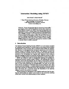
Modeling Subsea Soil-Structure Interaction of Offshore Wind Turbine Foundations in the Maryland Wind Energy Area Ryan Green Introduction As offshore wind turbines continue to grow in size and capacity, the foundations supporting them must also become more robust [1]. • Typical number of load cycles in 20 year life: ~ 108 = 100,000,000 rotor rotations Jacket (or lattice structures) are quickly emerging as the optimal support for large offshore wind turbines for several reasons: [2] • Experience reduced wave loads due to small cross section Table 1: Specifications of Reference turbine [1] • Have been used to support Oil and Gas platforms in water as deep as 900 meters • Have much lower mass, but similar structural stiffness as monopile and gravity base foundations. • Can be supported by both long, driven piles or multiple suction-bucket caissons.
Suction buckets further improve the jacket concept in comparison to driven piles [2]. • Do not require environment-damaging pile driving and instead use suction to install • Do not penetrate as deep as pile foundations (8-13 meters of penetration vs 50 meters or more) • However, site specific conditions can affect ultimate stability of the structure: [3] • May lose suction and stability in soils considered heterogenous due to varying pore sizes. Predicting long term behavior of a foundation in soil requires a thorough understanding of: 1. Sediment stratigraphy and geotechnical properties of the site as a function of depth, using available geophyisical and geotechnical data [4] 2. Forces and loads acting on the structure that determine soil-structure interaction using Finite-Element Modeling in ABAQUS CAE 6.14 [5].
Figure 1: Map of BOEM designated lease area known as the Maryland Wind Energy Area
Geophysical and Geotechnical Data 1. Geophysical Data (2013 MD Geological Survey HRG Survey): • Multibeam bathymetry to measure depth of seafloor • Medium penetration multi-channel sparker seismic reflection system to map medium soil stratigraphy • Estimate characteristic soil unit thicknesses and relative densities using SonarWiz [9].
Problem Description • A suction caisson supporting the loads of the INNWIND 10 MW Reference Wind Turbine in the MWEA is simulated. • Only interactions after caisson installation are considered; the caisson is “wished” into place. • The caisson at the foot of each leg of the jacket is modeled independently as undergoing either tension or compression due to cantilever action [6]. • The response forces exerted by the soil change depending on the direction and magnitude of the load [7].
ABAQUS CAE Model Specifications Geometry: • Must be large enough to ensure zero displacement at edges of soil domain [8] • Must be 3-dimensional, since loads are 3-dimensional [8] Mesh and Element Type: • Six-noded elements (C3D6) shaped as a triangular prism (wedge) • 40,372 elements = 242,232 nodes • (ABAQUS CAE Student license limit: 1000 nodes)
2. Lab Analysis of In-situ soil samples: • Textural analysis of Sediment Cores (~5 meters of penetration) and Surficial Grabs • Obtained by MD Geological Survey • Determine Soil type, unit weight, and particle size distribution as a function of depth into seafloor • Cyclic-triaxial testing of Deep Sediment Core (72 meters of penetration) • Obtained by US WIND in an unspecified location in June 2015 • Determine cyclic deviatoric stress and static max deviatoric stress for each each soil layer encountered (i.e. each layer’s response to cyclic loading) • NOT AVAILABLE TO THE PUBLIC
Soil Model Material Properties Proof of Concept Model – Single, Homogenous Layer of Dense Sand • Submerged Unit Weight = 8.2 KN/m3 [5] • Isotropic Elasticity • Young’s Modulus (Es) = 60,000 KN/m2 [5] • Poisson’s ratio (νs) = 0.3 [5] • Mohr-Coulomb Plasticity • Angle of Internal Friction (ϕ’) = 39 degrees [5] • Angle of dilation (ψ) = 9 degrees [5]
The Next Step
Figure 2: Finite Element Mesh and Geometry for 3-dimensional model of soilstructure interaction.
References
Figure 3: Conceptual drawing of the forces acting on the soil and caisson both under tension and compression inset with a 3-dimensional free body diagram.
[1] Kalenteridis, S., 2015, TUDelft, “Innovative Rotor Design Concepts for a 10 MW Wind Turbine” [2] Morch, C., 2014, DONG Energy Geotechnical Presentation, “The suction bucket jacket – a new wind turbine foundation concept” Nov. 20, 2014 [3] Feld, T., 2006. Geotechnical Analysis Requirements: Soil Investigations for Offshore Wind Turbine Projects. WindTech International 22 – 25. [4] Innwind.eu, 2014, Deliverable D4.3.2, “Innovative Concepts for Bottom-Mounted Structures” [5] Chung, J., 2007, B. Eng. Dalhousie University, “physical modeling of suction caissons loaded in two orthogonal directions for efficient mooring of offshore wind platforms”, Masters thesis [6] Innwind.eu, 2013, Deliverable 1.2.1, “Definition of the Reference Wind Turbine” [7] Stromblad, N., 2014, Chalmers University of Technology, “Modeling of Soil and Structure Interaction Subsea” [8] Ahmed, S., 2015, Memorial University of Newfoundland, “Finite element modeling of suction caisson and large diameter monopile in dense sand under oblique and lateral load”, Masters thesis [9] Coastal Planning & Engineering, Inc., a CB&I Company, 2014. Maryland Energy Administration High Resolution Geophysical Resource Survey (Project Number DEXR240005) Final Report of Investigations
1. Obtain ABAQUS License to run Proof of Concept Model 2. Implement MWEA Model – Multi-layer soil stratigraphy as constrained by available geotechnical and geophysical data • Improve basic material properties to include porosity • Convert to Depth-dependent Elasticity (p-y method) • Initial modulus of subgrade reaction (k) [8] • Convert to Modified Mohr-Coulomb Plasticity • Angle of Internal Friction (ϕ’) and Angle of dilation (ψ) are varied with accumulated plastic strain as well as confining pressure [8]. • Requires a user subroutine written in FORTRAN.