IEEE POWER ELECTRONICS LETTERS, VOL. 3, NO. 1, MARCH 2005
7
Modeling the Sequential Switching Shunt Series Regulator Ausias Garrigós, Jose A. Carrasco, Jose M. Blanes, and Esteban Sanchis
Abstract—This letter characterizes, in terms of the bandwidth and limit cycle frequency of its constituent subsystems, the sequential switching shunt series regulator — 4 , a high-efficiency, low-mass and volume power cell devised to power the next generation of regulated power buses in telecommunication spacecrafts. Transconductance power source modeling is used to obtain linear and nonlinear models. These are used to establish a design control strategy which involves the dynamic response in large load requirements or at the end of the satellite life. Simulations and experimental results are also given to demonstrate the validity of the model.
SR
Index Terms—Hysteretic control, regulated spacecraft power systems, sequential regulation systems, spacecraft power system modeling.
I. INTRODUCTION
T
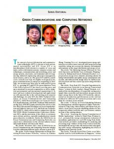
HE implements a spacecraft bus regulator and battery charger [1]–[3] operating under a bang-bang control mode [4], [5]. The structure is derived from the sequential switching [6], [7], and, as such, inherits its main adshunt regulator, vantage: no inductors are needed in either the bus regulator or the battery charge regulator (BCR). This feature is quite interesting in the battery chargers as it boosts the efficiency to 98% and it exhibits a mass reduction with respect to conventional PWM power converters [8]. In order to eliminate the BCR cirintroduces a second switch that makes each solar cuit, the panel operate in three possible positions: supply the bus, charge the battery or shunt its current to ground. The complete solar array has each panel in one of these three possibilities. Two feedback loops control the switches in order to stabilise the power bus while charging the batteries with the unused panels or dissipating the energy not required, as can be observed in Fig. 1. As shunted power cells do not provide energy to the system and penalise in terms of mass, special care has to be taken during power system design in order to choose the correct number of power cells. The appropriate number should be chosen in such a way that a minimum number of power cells is shunted during the whole satellite life. In the usual operation mode two independent power cells are used to accomplish a fine regulation of
Manuscript received July 28, 2004. This work was supported by the Spanish Ministry of Science and Technology under Grant ESP2003-08905-C03-02 This work was presented in part in the 35th IEEE Power Specialist Conference, 2004, Aachen, Germany. This paper was recommended by Associate Editor J. A. Cobos. A. Garrigós, J. A. Carrasco, and J. M. Blanes are with the División de Tecnología Electrónica, Escuela Politécnica Superior de Elche, Universidad Miguel Hernández. 03202 Elche, Spain (e-mail:
[email protected]). E. Sanchis is with the Departamento de Ingeniería Electrónica. Universidad de Valencia. 46100 Burjassot, Valencia, Spain. Digital Object Identifier 10.1109/LPEL.2005.845163
Fig. 1.
S R power cell integrated in a regulated spacecraft power system.
Fig. 2. Power stage model and its linear approximation.
both subsystems. However, at the end of satellite life or even for large power requirements, only one power cell can be requested for both control loops, combining both control signals to operate one transconductance power source. Such situations will be detailed later and will lead to design criteria from the control loop point of view. This letter is organized as follows. Section II gives the mathematical nonlinear and linear models for the solar array power source operated in bang-bang mode; Section III describes the different operation situations, the interactions between battery and bus subsystems and the control equations derived from
1540-7985/$20.00 © 2005 IEEE
8
IEEE POWER ELECTRONICS LETTERS, VOL. 3, NO. 1, MARCH 2005
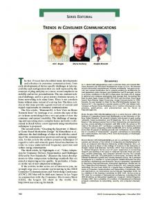
Fig. 3. (a) S
R operating at a medium load working condition. (b) S R operating at a maximum load working condition.
them; Section IV gives a complete MATLAB simulation model and results for different load conditions; Section V presents an experimental result of a low power breadboarded system; Section VI contains the conclusions and finally an Appendix is included where the battery limit cycle frequencies are derived.
, is the current of one section of the solar panel at where the bus voltage and close to its maximum power point and and are two opposite points in the hysteretic-comparators function for bus and battery trigger ladders, respectively. III. BUS AND BATTERY CONTROL LOOPS. LOAD DEPENDENCE
II. MODELLING THE SOLAR ARRAY POWER SOURCES OPERATING IN BANG-BANG MODE , the control technique leads to a variable In the switching frequency which in turn leads to a nonconventional power source model. A large signal model of the whole solar array is derived from the behavior of each individual cell. In practice, solar arrays are composed of individual panels that handle a proportional part of the overall current. Each panel power cell. At the system level, the forms part of an cell is determined by the battery and working of each bus error voltages interacting with hysteretic comparators that trigger a three-state switch. The hysteretic comparators are designed to form a ladder that univocally defines the state of the system. These comparators can be placed with a dead zone between them or nested in such a way that the low comparator cell is lower than the upper level of cell , level of the as shown in Fig. 2. The second option is preferred in the bus regulator, since it improves the equivalent transconductance and it allows the small bus capacitance value that meets the standard in [9]. By considering a nonlinear function of the hysteretic-comparator of each cell, the bus and battery regulators can be idealized as nonlinear transconductances. Also, a simple linearization of those functions is obtained by joining the two extreme points of the complete ladder by a straight line, as depicted in Fig. 2. Linear equations of conductance for bus and battery power stages are shown in (1):
(1)
Once the linear approximation is achieved for the power sources, classical control is directly applicable but two different approaches must be considered depending on how many power cells are involved in the fine regulation of both subsystems: one or two power cells. As demanded by the load, the power system will be able to operate either in a medium load working condition, where the bus and battery will be regulated with different sections panels, and therefore, regulation loops will be independent, or in a maximum load working condition, where both regulators will compete for the same section panel, as can be seen in Fig. 3(a) and (b). The first case is usual at the beginning of life, since the power system is oversized and one or more power cells are permanently shunted. As time passes, several effects reduce the available power from the solar panel including radiation effects, micrometeorites and many others. But even at the beginning of the satellite life, changes in the power extracted from the panel occur due to variations of solar flux during the year, solar panel pointing, etc. When the bus load and battery charge capability exceed the available solar array power, the system is regulated by a single power cell. In this case, a logic circuit is necessary to give priority to bus regulation rather than battery charge. A. Medium Load Working Condition From the dynamic analysis point of view, in this load regime both subsystems are considered independent. The solar sections involved in fine regulation will switch between two positions: BATTERY or BUS and GND. The rest of the power cells are connected to GND in case of shunted cells or permanently connected to the main bus or battery bus. Both converters are modeled using the same approximation employed in [6] for the bus regulator. Linear equations, and consequently linear system approximations, are derived from the fact that the power source
GARRIGÓS et al.: MODELLING THE SEQUENTIAL SWITCHING SHUNT SERIES REGULATOR
9
TABLE I
S R EQUATIONS FOR DIFFERENT OPERATION MODES
is working as current source controlled by the error signal of each loop (see Table I). A detailed derivation of the battery limit cycle frequency in medium and maximum load working conditions loop is given in the Appendix.
is the attenuator resistor network formed by and and the rest of parameters are shown in Fig. 9 or listed in the Appendix IV. SIMULINK MODELLING
B. Maximum Load Working Condition As shown in Fig. 3(b), loop dependences will affect the nominal switching pattern, which was clearly a 2-position switch – BUS to GND and BATTERY to GND – and will transform it into a 3-position switch – BUS, BATTERY and GND. Assuming the compensator design established by the equations in the medium load working condition, two different situations can be extracted depending on the crossover frequency of each subsystem. The feedback loops are then designed in accordance with the two possible cross-over frequency’s relative positions (see Table I). Less Than : In this case, the bat1) tery signal error is not able to follow the hysteresis limits, and multiple requests of different power cells by the battery system are produced. The battery switching frequency is modulated by the bus loop, and it is fixed at the same value, resulting in an increase in harmonics of the battery charging current. Bigger Than : Now, the battery 2) error signal is maintained within operation limits, and, therefore, the current spectrum is well defined by low-frequency components due to the battery subsystem and high components given by the bus loop dynamic. The battery switching frequency is now related to the actual load current on the main bus, and it produces a frequency displacement in the fundamental component, keeping the higher harmonics at the fixed frequency given by the bus loop.
The system consists mainly of two different loops, the bus and the battery loop, as depicted in Fig. 4. Each loop has its own compensator, and both are connected to the power sources (solar array). In addition, the nonlinear characteristic of the transconductance power source is modeled as a hysteretic function with a logic function, which establishes priorities in the bus over battery regulation. A. Simulation Results Simulations results in Figs. 5 and 6 show a load step from 12.5% to 81.25% of the total current which implies a maximum load condition with both battery control velocities, kHz and kHz and Hz. Also, Fig. 5 shows the modulation effect just mentioned, giving a battery charging current with a large content of high frequency components and an error signal that does not follow their hysteretic limits when the battery loop bandwidth is higher than bus loop bandwidth. V. EXPERIMENTAL RESULTS A low-power prototype has been designed and breadboarded following the European Space Agency power specifications [9]. The whole system is formed by four power cells and the solar panel is simulated by four current sources. In each subsystem, two main error amplifiers with four bang-bang compensators each– two per power cell –are implemented.
10
Fig. 4.
IEEE POWER ELECTRONICS LETTERS, VOL. 3, NO. 1, MARCH 2005
Simulink–Matlab S
R model (four power cells).
Fig. 5. Bus voltage, battery charging current, and battery error signal when !
The three-position switch consists of five transistors, two of them providing the current to the bus and the battery, and the last three making the logic function which governs the power switches [1], as can be observed in Fig. 9. The main characteristics of this prototype can be found in Table II. A good agreement between model predictions and measurements has been found in the first results using a bus crossover frequency higher than the battery crossover frequency and independent loop regulation mode, as shown in Figs. 7 and 8.
.
VI. CONCLUSIONS A mathematical model of the is presented, analyzed, and system than makes used to calculate the control loops of an optimal use of power from a solar panel. A three-state switch may regulate the bus while keeping a charging current to the batteries at large power demands when there is only one panel available. Experimental validity of the results is presented from an implemented breadboard.
GARRIGÓS et al.: MODELLING THE SEQUENTIAL SWITCHING SHUNT SERIES REGULATOR
Fig. 6. Bus voltage, battery charging current, and battery error signal when !
>!
11
.
Fig. 7. Bus voltage ripple (Ch1), bus error voltage (Ch4), and shunt switch driving signal (Ch2). 50 V bus voltage and 1 A load consumption.
Fig. 8.
Charge battery current (Ch3) and battery error voltage (Ch4): 36 V battery arrangement and 1 A average charging current.
12
Fig. 9.
IEEE POWER ELECTRONICS LETTERS, VOL. 3, NO. 1, MARCH 2005
S R implemented power cell.
TABLE II BUS AND BATTERY SPECIFICATIONS. THESE SPECIFICATIONS FOLLOW ESA POWER STANDARDS AND DESIGN RATIONALE [8]
In that integrator type compensator, the Verrorbat signal can be expressed as: (8) where battery loop error signal errorbat is defined by
(9) By substituting the Verrorbat signal in both time intervals, and , the limit cycle frequency is easily obtained. APPENDIX The purpose of this appendix is to derive the battery limit cycle frequencies listed in Table I for different load working conditions. Main variables included in the analysis are defined as follows: Voltage reference of battery compensator. Resistor of the battery compensator (Integrator type). Capacitance of the battery compensator (integrator type). High battery comparator threshold. Low battery comparator threshold. Load current. A. Limit Cycle Frequency in Medium Load Working Condition Limit cycle frequency can be obtained easily by observing the charging current signal of the battery and the integration of the error signal via the compensator (see Fig. 10).
(10)
B. Limit Cycle Frequency in Maximum Load Condition When Observing Fig. 11, the limit cycle frequency equation can be expressed by:
(11)
GARRIGÓS et al.: MODELLING THE SEQUENTIAL SWITCHING SHUNT SERIES REGULATOR
13
On the other hand,
is also given by (13)
where and
and are the Verrorbat signal during , respectively.
(14) Finally, substituting Eq. (4) in Table I (12), (13), (14) into (11), and arranging terms, the limit cycle frequency is calculated. Fig. 10. Battery charging current and control signal in medium load working condition.
(15) REFERENCES
Fig. 11. Battery charging current and control signal in maximum load working >! . condition and !
Again, can be obtained by integration of the signal error during that time interval, giving
(12)
[1] A. Capel, D. O’Sullivan, and J. C. Marpinard, “High power conditioning for space applications,” Proc. IEEE, vol. 76, no. 4, pp. 391–408, 1988. [2] A. K. Hyder, R. L. Wiley, G. Halpert, D. J. Flood, and S. Sabripour, Spacecraft Power Technologies. London, U.K.: Imperial College Press, 2000. [3] P. Fortescue, J. Stark, and G. Swinerd, Spacecraft Systems Engineering, Third ed. New York: Wiley, 2003. [4] A. Capel and P. Lecointe, “Dispositif de Generation d’Energie Electrique Pour bus d’Alimentation,” Patent FR2 828 962, 2003. [5] A. Capel and P. Perol, “Comparative performance evaluation between the S4R and the S3R regulated bus topologies,” in Rec. IEEE Power Electronics Specialists Conf., 2001, pp. 1963–1969. [6] D. O’Sullivan and A. Weinberg, “The sequential switching shunt regulator (S3R),” in Record, ESTEC Spacecraft Power Conditioning Seminar, 1977, ESA SP-126, pp. 123–131. [7] P. Perol, “Another look at the sequential switching shunt regulator,” in Record, Fifth European Space Power Conf., 1998, ESA SP-416, pp. 79–84. [8] A. Capel, “The power system of the multimedia constellation satellite for the Skybridge Missions,” in Rec. IEEE Power Electronics Specialists Conf., 1998, pp. 1913–1930. [9] Power Standard, ESA Std. ESA PSS-02-10.