Sep 14, 2004 - series active compensators used in power quality ... compensate for the main types of disturbances in electrical power systems, is considered.
Advanced common control method for shunt and series active compensators used in power quality improvement M.A.E. Alali, Y.-A. Chapuis, S. Saadate and F. Braun Abstract: An advanced common control method for shunt and series active conditioners, which compensate for the main types of disturbances in electrical power systems, is considered. If shunt and series actives conditioners are already well known as good compensation solutions for power quality improvement, it is also admitted that they generate some undesired components at switching frequency. To avoid these propagation problems, conditioner designers proposed a highorder output filter associated to a specific controller based on the RST control method. However, by applying this controller, it can be observed that a phase lag between the reference and the injected signal appears in the current and voltage control loop, which damages harmonic compensation. Therefore, a new RST controller is proposed, called RSTimp, to overcome the phase lag effects over the entire bandwidth for both active conditioners. The RSTimp proposed control method is validated through SABER simulations. These simulations show very good active conditioner performance in terms of rapidity, tracking and robustness for both current and voltage compensation.
1
Introduction
In most industrial countries, the shunt active conditioner is becoming an alternative solution to compensate for current disturbance in electrical installations [1]. However, shunt active conditioner inverters generate some undesired components at switching frequency. These components can be propagated through the output filter and affect line current and voltage. These effects can also appear with a PWM inverter with a high switching frequency. To avoid these effects, an auxiliary passive filter associated to a firstorder output filter can be inserted either in the network side or at the inverter output. Unfortunately, this solution can cause secondary effects such as resonance problems. A solution is to include a third-order output filter, also called a T-type filter, with current control based on hysteresis or sliding mode [2]. However, this proposal causes switching frequency variation and consequently damages the power converter switches. Finally, to overcome these problems, a PWM inverter with an RST controller for the current loop is proposed. In this case, the PWM inverter output voltage, and consequently the injected current of the shunt active conditioner, are controlled by the RST controller. However, this controller cannot guarantee good compensation. Although
r IEE, 2004 IEE Proceedings online no. 20040679 doi:10.1049/ip-epa:20040679 Paper first received 8th July 2003 and in revised form 30th April 2004. Originally published online: 14th September 2004 M.A.E. Alali is with the Faculty of Electrical Engineering, University of Aleppo, Aleppo, Syria Y.-A. Chapuis and F. Braun are with the LEPSI-23, Rue du Loess, BP 2067037 Strasbourg Cedex 2, France S. Saadate is with the GREEN, France Universit!e, Henri Poincar!e, 54500 Vandoeuvre-l"es-Nancy, France
658
the tracking of the magnitude of identified disturbances is quite good, phase lag between the reference and the injected signals appears in the current control loop. For other disturbances such as voltage harmonics, unbalanced voltage and voltage sag, many studies have already addressed these problems. Series active conditioners compensate for unbalanced voltage and also voltage sag [3]. However, the phase lag effect, previously identified in the shunt active conditioner, prevents the series conditioner from compensating properly for voltage harmonics. To solve all those problems, in both shunt and series active conditioners, this paper considers an improved common control method based on the RST controller, called RSTimp.
2
2.1
Active conditioner structures
General structure
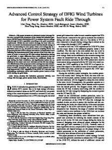
The shunt active conditioner is generally composed of a control part and a power part, including a PWM voltage source inverter, a DC capacitive storage system and an output filter. In electrical power systems, most power quality problems are associated with voltage harmonics, unbalanced voltages and voltage sag. Voltage sags are generally caused by faults or starting currents of large power machines. However, unbalance and harmonic voltages are usually generated by unbalanced consumption and non-linear loads. They can also be caused by a disturbance or a distortion of the network EMF. Many series active conditioner structures have been proposed [4, 5]. One well-known structure includes a control part and a power part composed of a three-phase voltage PWM inverter, a DC capacitive storage system, an output filter and three single-phase transformers [6, 7]. In both active conditioner structures, the control part is composed of an identification method and a control loop of IEE Proc.-Electr. Power Appl., Vol. 151, No. 6, November 2004
injected current or voltage disturbances
electrical network es ~
Rs
linear, non-Linear,
Ls
or protected load Xinj 1,2,3 measured electrical values
Vdc output
PWM
filter
VSI
DC capacity storage system
control signals current or voltage disturbances identification
xref 1,2,3
current or voltage control loop
current or voltage active conditionner controller
Fig. 1
Common structure of shunt and series active conditioners
the disturbance. We talk about identified current or voltage (Xref1,2,3) and injected disturbance (Xinj1,2,3) for both shunt and series active conditioners. Figure 1 shows a common structure of shunt and series active conditioners and the power environment, including a three-wire power network and a non-linear or protected load.
Table 1: Electrical network characteristics Shunt active conditioner
Series active conditioner
Rs=0.25 mΩ; Ls=19.4 µH
Electrical network (1 MVA, ucc = 4%)
1st Order Filter
2.2
Lf,Rf
Output current and voltage control
A three-phase voltage source inverter (VSI) is used to generate the current and voltage references that are injected to the network supply. The VSI is controlled by a PWM. The VSI is connected to the electrical network by a passive output filter. The output filter must be designed to reject components at the switching frequency generated by the PWM VSI.
Lf = Lf 1 + Lf 2 Rf = Rf 1 + Rf 2 Output
2nd Order Filter
T-type Filter (3rd Order Filter) Lf 2,Rf 2
Filter
Lsf , Rsf
Lf 1,Rf 1 Csf Cf
2.2.1 Transfer functions of output filters: The output filter is modelled by the following equations: B1 ðsÞ B2 ðsÞ Vinv ðsÞ þ Xper ðsÞ Xinj ðsÞ ¼ AðsÞ AðsÞ
Rsf =25 mΩ; Lsf = 400 µH
Lf 1= 90 µH, Rf 1= 5 mΩ;
ð1Þ
8 AðsÞ ¼ a1 sn þ a2 sn�1 þ :: þ an s þ anþ1 > > > < with B1 ðsÞ ¼ b11 sn�2 þ b12 sn�3 þ :: þ b1ðn�2Þ s þ b1ðn�1Þ > > > : B2 ðsÞ ¼ b21 sn�1 þ b22 sn�2 þ :: þ b2ðn�1Þ s þ b2n
Csf =250 µF
Lf 2= 70 µH, Rf 2= 5 mΩ; Lf = 200 µF, Rf = 160 mΩ; Storage capacitor
Cd = 4.4 mF; Vdc =840 V
Direct source: Vdc =840 V
Cut-off frequency of the output filter
1900 Hz
500 Hz
Switching frequency
12.5 KHz
12.5 KHz
ð2Þ B1(s)/A(s) is the transfer function of the output filter and B2(s)/A(s) represents a disturbance model. Vinv(s) is the inverter output voltage and Xper(s) is considered as a disturbance. n is the order of the output filter transfer function.
disturbance model are given by: 8 a1 ¼ ðLs þ Lf 2 ÞLf 1 Cf > > > > > " # > > ðLs þ Lf 2 ÞRf 1 Cf þ ðRs þ Rf 2 ÞLf 1 Cf þ > > > a2 ¼ > > > < þðL þ L þ L ÞR C
2.2.2 Shunt active conditioner: third-order output filter: For a better filtering of the switching
" # > > ðLs þ Lf 2 Þ þ Lf 1 þ ðRs þ Rf 2 ÞRf 1 Cf þ > > > > a3 ¼ > > > þðRf 1 þ Rs þ Rf 2 ÞRf Cf > > > > : a4 ¼ R f 1 þ Rs þ R f 2
frequency, a T-type third-order output filter is proposed (cf. Table 1). The transfer functions of the output filter and IEE Proc.-Electr. Power Appl., Vol. 151, No. 6, November 2004
f1
s
f2
f
f
659
and
8 b11 > > > > > > b12 > > < b21 > > > > b22 > > > > : b23
compensated for by the closed loop, as shown later. From Fig. 2 and (1), we can write the following equation:
¼ Rf C f ¼1 ð3Þ
¼ Lf Cf
ð5Þ
¼1
structure uses a passive output filter (Lsf, Rsf, Csf) of second order (cf. Fig. 1 and Table 1). The transfer functions can be obtained from the following parameters: 8 8 b11 ¼ 1 a1 ¼ Lsf Csf > > > > > > < < b21 ¼ Lsf ð4Þ a2 ¼ Lsf Csf and > > > > > > : : b22 ¼ Rsf a3 ¼ 1
Control methods
The cut-off frequency of the closed-loop control must be high enough not to modify the reference signal (Xref). This frequency must also be far enough from the switching frequency to model the inverter as a simple gain. The control criteria of the closed loop must ensure good reference tracking and short response time. We propose in a first approach to study an RST control method.
3.1
ðTB1 ÞðsÞ ðSB2 ÞðsÞ Xref ðsÞ þ Xper ðsÞ ðSA þ B1 RÞðsÞ ðSA þ B1 RÞðsÞ
¼ ðRf þ Rf 1 Þ
2.2.3 Series active conditioner: secondorder output filter: The series active conditioner
3
Xinj ðsÞ ¼
RST control method
where R(s), S(s) and T(s) are the controller polynomials. The two parts of (5) represent the closed-loop transfer function in terms of tracking and disturbance effects. The order of R(s) and S(s) is the same as the output filter B1(s)/ A(s). Thus, from (3) and (4), the order of R(s) and S(s) is n ¼ 3 for the current control loop and n ¼ 2 for the voltage control loop. T(s) can be given by a simple gain as Xinj(s)/ Xref(s) ¼ 1 when the Laplace variable (s) tends to 0.
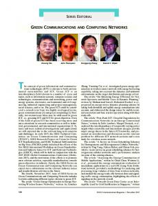
3.1.2 Phase lag effect problems: The RST control method is generally used when the reference to be tracked is either a constant or a single-frequency signal with relatively low frequency. In the single-frequency case, phase lag (g) between reference (Xref) and injected (Xinj) signals is acceptable. However, the phase lag is unacceptable when the reference signal includes multiple frequencies, as phase lag increases with frequency. Moreover, the higher the order of the controlled system, the higher the phase lag is. Figure 3 illustrates the phase lag effect for a distorted signal (Xsig), which is not correctly compensated for (Xreal), compared to the ideal form (Xideal).
3.1.1 Common control method principle: The RST controller is based on a pole-placement design, as shown in the general scheme of Fig. 2. This method can satisfy most control criteria such as good robustness. For the shunt active conditioner, the disturbances (Xper) are caused by the network voltage Vs(s). In this paper, the effect of this type of disturbance is compensated for by adding the same network voltage to the control signal u(s), as shown in Fig. 2. This voltage is necessary to prevent the fundamental current from passing from the network to the active conditioner. For the series active conditioner, the disturbances (Xper) are caused by the load current (IL). Indeed, the load current crosses the active conditioner and disturbs the injection voltage (Vinj). In this paper, this type of disturbance is
X sig
200 100 0 −100 −200 0 100 50 0
0.002 0.004 0.006 0.008 0.01 0.012 0.014 0.016 0.018 0.02 a X ref X inj �
−50 −100
0
200 100 0 −100 −200
0.002 0.004 0.006 0.008 0.01 0.012 0.014 0.016 0.018 0.02 b Xideal Xideal = Xsig − Xref Xreal = Xsig − Xinj
Xreal
0
Fig. 3
0.002 0.004 0.006 0.008 0.01 0.012 0.014 0.016 0.018 0.02 t, s c
Phase lag effect on compensation quality
system for voltage controller
system for current controller Vs(s)
IL(s)
B 2(s)
+
+
B 1(s)
+
+
B 2(s) /A(s)
1/A(s)
B 1(s) /A(s)
+
+
Xper(s)
Xref (s)
Fig. 2 660
T(s)/R(s)
+−
R(s)/S(s)
u(s)
system
Xinj(s)
control loop
General RST controller scheme IEE Proc.-Electr. Power Appl., Vol. 151, No. 6, November 2004
3.2
Improved RST control method (RSTimp)
3.3
To overcome the phase lag effect and achieve good compensation performance, a first approach was to propose linear controllers, such as PI, PID, H2, HN etc. However, as they were initially proposed in the literature, these solutions amplified more than they reduced the phase lag problem. Recently, new robust controllers based on H2 and HN modes have been proposed in the literature to compensate for these undesired effects [8, 9]. In this context, we propose a control method based on an advanced linear control mode, which treats particularly the phase lag problem. This advanced control method is based on the same principle used in a classic RST where zeros have been placed in the transfer function of the closed loop. These zeros are placed to reduce gain and phase error. Error minimisation e(s) is determined by the equation from Fig. 2: � � ðTB1 ÞðsÞ � 1 Xref ðsÞ ð6Þ eðsÞ ¼ ðXinj � Xref ÞðsÞ ¼ DðSÞ
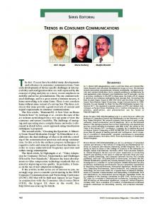
3.3.1 Current control loop: Figure 4 and Table 2 compare current reference tracking of the RST and RSTimp control methods. Gain and phase of the transfer function of the current closed loop Iinj(s)/Iref(s) are given in Table 2 for multiples of the fundamental frequency (Ff), from Ff to 31 Ff. In both control methods, gain remains at 0 dB for all frequencies, as shown in the Table 2. The RST control method is only used to compensate for unbalanced current or reactive current which occurs at the fundamental frequency 50 Hz. At this frequency, a phase lag of (�1.1161) is negligible. Beyond this, phase lag is no longer negligible and the shunt active conditioner cannot compensate for current harmonics. The improved RST control method works for phase lag over the entire bandwidth. In this method, little overshoot occurred at the cut-off frequency of the closed loop, as shown in Fig. 4a. This frequency is high enough so that there is no risk of having a harmonic current component. Furthermore, a little dip between 650 and 1150 Hz can be observed in Fig. 4b. This dip is caused by the order of the T(s) polynomial, which is 3 in this study and insufficient to ensure zero phase lag. Indeed, the polynomial degree of T(s) is limited by the causality of the transfer function T(s)/R(s) (cf. Fig. 2).
whose D(s) ¼ (AS+B1R)(s) (arbitrary stability polynomial). From (6), we can obtain the transfer function as given by: � � eðsÞ ðTB1 � DÞðsÞ ¼ ð7Þ Xref ðsÞ DðsÞ To reduce the error e(s) to zero, the numerator of (7) must tend to zero. Since R(s) and S(s) are already defined, only T(s) can reduce the error e(s). Moreover, the order of T(s) must be chosen so that the transfer function T(s)/R(s) (cf. Fig. 2) is causal (degree(T)rdegree(R)), as given in (8). The stability of the system, defined by a classic RST method, is not modified if the T(s) polynomial is stable: T ðsÞ ¼ t1 sn þ t2 sn�1 þ . . . þ tn s þ tn�1
3.3.2 Voltage control loop case: Figure 5 and Table 3 compare the signal reference tracking of the two control methods. In Table 3, gain and phase of the transfer function Vinj(s)/Vref(s) of the closed loop are given for each method (RST, RSTimp). For all frequencies, gains are satisfactory with the two methods, as shown in Table 3.
ð8Þ
By using (8) and replacing s ¼ jo with o the angular frequency, the numerator of (7) becomes: ðTB1 � DÞðjoÞ ¼ Re ðoÞ þ jIm ðoÞ
Control method synthesis
Iinj/Iref
50
ð9Þ
RSTimp
0 gain, dB
To make (9) tend to zero, both the real Re(o) and imaginary Im(o) parts must tend to zero. This constraint means that there are two equations for each frequency of a placed zero. In this study, T(s) is a third-order and second-order polynomial for current and voltage control, respectively. For current control, a third-order T(s) polynomial is the maximum order satisfying the causality of the transfer function T(s)/R(s). Taking account of the unknown parameters in this case (t1, t2, t3, t4), only two frequencies have to be chosen. Zeros should be placed near the slowest poles of the closed-loop transfer function. For the voltage control case, T(s) is a second-order polynomial, which is the maximum order that still respects the causality of T(s)/R(s) transfer function (cf. Fig. 2). Taking account of the unknown parameters in this case (t1, t2, t3), two frequencies have to be chosen. Zeros are again placed near the slowest poles of the closed-loop transfer function.
−50 RST
−100 −150
a
phase, deg
180 RSTimp
0 −180 RST
−360 −540
102
103 frequency, Hz
104
105
b
Fig. 4 Closed-loop transfer function with RST and RSTimp controllers
Table 2: Two control methods comparison for current control (RST and RSTimp) F, Hz
50 Gain, dB
RST
Phase, deg Gain, dB
RSTimp
Phase, deg
250
350
550
1
1
1
1
�1
�8
�11
�18
1
1
1
1.1
�0.01
�0.54
�1.35
�4.36
IEE Proc.-Electr. Power Appl., Vol. 151, No. 6, November 2004
650 0.99 �21 1.1 �6.4
850 0.98 �27 1 �10.1
950 0.98 �30 0.98 �11.2
1150 0.97 �37 0.9 �10.2
1250 0.97 �40
1450 0.95 �46
1550 0.94 �49
0.9
0.9
0.9
�9.78
�6.50
�4.78 661
The RST method is only used to compensate for voltage sag or unbalance voltage which occurs at 50 Hz. At this frequency, the resulting phase lag (�1.2781) can be considered negligible. Above this frequency, phase lag is no longer negligible and the series active conditioner cannot compensate for voltage harmonics. The improved RST control method is valid for all bandwidth frequencies. Noted that a little overshoot occurs at the cut-off frequency where there is no risk of having a voltage harmonic component. 4
source line current pattern is good. The phase 1 current THD was been 21.16% for the nonlinear load and 1.5% for the source current after compensation. To show the efficiency of the T-type output filter in switching frequency filtering, another simulation in almost the same conditions is illustrated in Fig. 7. The T-type output filter is replaced by a first-order filter which consists of one reactance with its inner resistor, as given in Table 1. As can be observed in Fig. 7, the switching frequency components included in the injected current (Iinj1) prevent us from estimating the good tracking of the identified harmonics (Iref1). The spectrum analysis has shown that for conventional harmonics, we have almost the same THD as with the T-type filter. On the other hand, taking account of the switching frequency, the THD of non-linear load current becomes 13.9%. This result demonstrates clearly the pertinence of using a high-order output filter.
Simulation results
4.1
Shunt active conditioner application
The network is made up of a sub-transformer 20/0.4 kV, 1 MVA, ucc ¼ 4%. The non-linear load is a 100 kVA six-pulse thyristor rectifier. A 100 kW linear unbalanced load is connected in parallel with the non-linear load. The shunt active conditioner is tested in two simulation cases. In these simulations, the shunt active conditioner has a T-type output filter and injected current is controlled by the RSTimp controller. Direct voltage storage capacitor Vdc is regulated by a PI controller. The shunt active conditioner recharges the capacitor. The system rating values considered in the general structure are given in Table 1.
200.0
IN-L1
A
0
A
−200.0 200.0
Iref 1 Iinj1
0
4.1.1 Current harmonic compensation: In the −200.0 400.0 A
first simulation case, current harmonics generated by the non-linear load with a triggering angle a ¼ 01 was applied. Figure 6 shows the results, for phase 1, of nonlinear load current (IN-L1), the superposition of current reference and injected current (Iref1, Iinj1) and source line current (IL1). From Fig. 6, we remark that there is no phase lag between current reference and injected current. Thus, the
IL1
200.0 0 −200.0 −400.0 0.1
Fig. 6
0.11
0.12
0.13 t, s
0.14
0.15
0.16
Transient analysis of current harmonic compensation
Vinj / Vref 200.0
RSTimp −50
RST
−100 −150
−200.0 200.0
a A
0
0
RSTimp
−90 RST
−180
−200.0 200.0
−270 −360 101
Iref 1 Iinj1
IL1
A
phase, deg
IN-L1
0
A
gain, dB
0
0 102
103 frequency, Hz
104
105 −200.0 0.06
b
Fig. 5 Closed-loop transfer function with RST and RSTimp controllers
Fig. 7
0.07
0.08
0.09 t, s
0.1
0.11
0.12
Switching frequency effect on harmonics compensation
Table 3: Two control methods comparison for voltage control (RST and RSTimp) F, Hz RST
50 Gain, dB Phase, deg
RSTimp
Gain, dB Phase, deg
662
250
350
550
650
850 1.05
950
1
1
1
1
1
�1
�6
�9
�14
�17
1
1
1
1
1
1.06
1.07
1.2
�0.15
�0.5
�0.5
0.3
0.7
1.5
1.5
0.5
�22
1.05
1150
�24
1.1 �29
1250 1.1 �32 1.24 �0.8
IEE Proc.-Electr. Power Appl., Vol. 151, No. 6, November 2004
4.1.2 Current harmonic, reactive power and negative sequence current compensation: In
phase angle is zero, which demonstrates good power factor compensation.
this simulation, shunt active conditioner was studied to compensate for current harmonics, reactive power and negative sequence current caused by an unbalanced linear load. Reactive power is caused by the triggering angle a ¼ 421. Figure 8 shows simulation results of transient analysis for this case. The three-phase non-linear load current (IN-L1,2,3), unbalanced linear load current (IL-L1,2,3) and source current (IL1,2,3) are presented. Current reference and injected current (Iref1,2,3, Iinj1,2,3) are superimposed for each phase. There is no phase lag between current reference and injected current. Current source patterns prove that the compensation quality is good. Indeed, the current source is balanced and almost harmonic free. The source current
4.2
Series active conditioner application
The supply is from a sub-transformer 20/0.4 kV, 1 MVA, ucc ¼ 4%. The load is a 100 kVA series R-L, with a peak current of I# ¼ 205 A, and power factor cos j ¼ 0.8. The system rating values are given in Table 1.
4.2.1 Single-phase voltage sag compensation: Figure 9 shows a transient analysis using an RST controller for an 80% single-phase voltage sag on phase 1. From these results, a negative voltage rate of 36% is obtained for the network side, compared to 0.669% for the load side after compensation. Moreover, since reference
200.0
IN-L1,2,3
A
0 −200.0 200.0
IN-L1,2,3
A
0 −200.0 200.0
Iref 1, Iinj1
A
0 −200.0 200.0
Iref 2, Iinj 2
A
0 −200.0 200.0
Iref 3, Iinj 3
A
0
A
−200.0 400.0 200.0 0 −200.0 −400.0
IL1,2,3
0.1
0.11
0.12
0.13
0.14
0.15
0.16
t, s
Fig. 8
Transient analysis of current disturbances compensation
V
400.0
Vs1,2,3
200.0 0 −200.0 −400.0
A
200.0
IL1,2,3
0 −200.0
V
400.0
Vref 1
200.0 0 −200.0
Vinj1
−400.0
V
400.0
VL1,2,3
200.0 0 −200.0 −400.0 0.075
Fig. 9
0.1
0.125
0.15
0.175 t, s
0.2
0.225
0.25
0.275
Transient analysis of voltage sag compensation using RST
IEE Proc.-Electr. Power Appl., Vol. 151, No. 6, November 2004
663
5
tracking time is negligible, compensation can be considered instantaneous. The simulation results for the same case using the RSTimp controller are very satisfactory [7]. Indeed, the load voltage amplitude is 324.2 and 324.95 V by using RST and RSTimp, respectively. The gain and phase at fundamental frequency, given in Table 3, explain these results which, in addition to the almost instantaneous response, show the effectiveness of the two controllers for this type of disturbance.
In this paper, shunt and series active conditioners using an advanced common control method have been studied in order to improve power quality in electrical network. This study is based on a third- and a second-order output filter proposed, respectively, for the shunt and series active conditioners, to ensure that the switching frequency has been filtered out of the injected signal. However, such compensation conditions require a specific controller, such as the improved control method called RSTimp, proposed in this paper. The RSTimp controller allows good performances in terms of rapidity, tracking and robustness to compensate for both current and voltage disturbances at the fundamental and harmonic frequencies, while overcoming phase lag that can appear in classic RST controllers. The good results in compensation obtained by the proposed specific control method, RSTimp, promise a future trend for modern control methods such as robust control, optimal control, adaptive control etc. The controllers based on these methods have to take into consideration the new problems of magnitude and phase tracking, over a large frequency band. The tracking has to be performed almost perfectly with a good robustness and a short response time, without increasing the controller’s order to assure its hardware realisation. These constraints are a good challenge
4.2.2 Unbalance voltage and voltage harmonics compensation: For this case, an unbalanced voltage and voltage harmonics compensation was studied. The three phase voltages Vs-max1 ¼ 216 V, Vs-max2 ¼ 263 V, Vs-max3 ¼ 295 V having, respectively, the phases 151, �1301, 1101, cause a negative voltage rate of 13.6%. Voltage harmonic compensation concerns only the 5th, 7th, 11th and 13th harmonics with individual harmonic distortion rates of 10, 7, 1 and 1%, respectively, compared to the nominal voltage of 325 V. Only one control method is proposed in this part: the RSTimp controller. Indeed, the RST controller, handicapped by the phase lag as given in Table 3, could not guarantee good compensation. Transient analysis is illustrated in Fig. 10 After compensation, negative voltage ratio is 0.015% for the load side. The angle of voltage load becomes 3.21 for phase 1, shifted by �1201 and +1201 for phases 2 and 3, respectively.
V
Conclusion and discussion
Vs1,2,3
400.0 200.0 0 −200.0 −400.0
V
200.0
Vref 1
0
Vinj 1
−200.0
V
200.0
Vref 2
0
Vinj 2
−200.0
V
200.0
Vref 3
0
Vinj 3
V
−200.0 400.0 200.0 0 −200.0 −400.0 0.08
Fig. 10
VL1,2,3
0.09
0.1
0.11
0.13
0.14
0.15
0.16
Voltage sag and voltage harmonic compensation using RSTimp
The simulations prove that the proposed designs meet the objective of good tracking and consequently realise a good compensation of all electrical disturbances. These designs present a neutral function under perfect conditions of the electrical network. Indeed, when there is no voltage sag on phase 1, the identified and the injected signals are almost zero. If the proposed equipment does not achieve the required perfect performance (tracking), this is due to the non-zero phase lags, even at 50 Hz. In addition to the PLL (phase-locked loop) effect which, if it can guarantee an accurate delivery of the positive sequence voltage angle and magnitude, its precision cannot be naturally perfect [7, 10]. 664
0.12 t, s
to the designers who work in the electrical, automation and microelectronics fields. The choice of a relatively high switching frequency is in fact an advantage for the proposed control methods, without compromising a practical realisation. Indeed, for the active filters intended to compensate for current harmonics generated by a 100 kVA non linear load, a 12.5 kHz switching frequency is largely applicable for the new generation of IGBTs, noting that the power rating of the active filter in this case is almost 30 kVA [6]. For larger loads, we consider that a parallel connection of the active filters with the same switching frequency can be realised. IEE Proc.-Electr. Power Appl., Vol. 151, No. 6, November 2004
All our research work covered by this paper, modelling, design and simulation, has been made in continuous time mode. For an eventual hardware discrete time realisation, all the models and designs have to be made directly in discrete time. Then, the controller has new constraints such as Nyquist frequency, sampling frequency, sampling time etc. These new aspects need more space to be discussed. 6
References
1 Akagi, H.: ‘New trends in active filters for power conditioning’, IEEE Trans. Ind Appl., 1996, 32, (6), pp. 1312–1322 2 Lapena, O.L., de Vicuna, L.G., Matas, J., Lopez, M., and Castilla, M.: ‘A sliding mode control design of an active power filter with a low-pass filter as input stage’. Presented at EPE-99, Lausanne, Switzerland, 1999 (CD-ROM) 3 Sannino, A., and Svensson, J.: ‘A series connected voltage source converter for voltage sag mitigation using vector control and a filter compensation algorithm’. Presented at the 35th IAS annual meeting of the 2000 IEEE Industry Applications Conf., Roma, Italy, October 2000, pp. 2476–2481
IEE Proc.-Electr. Power Appl., Vol. 151, No. 6, November 2004
4 Visoser, A.J., Mouton, T., and Enslin, J.H.R.: ‘Directed-coupled cascaded multilevel sag compensator’. Presented at the 31st IEEE annual Power Electronics Specialists Conference (PESC), Galway, Ireland, 2000 (CD-ROM) 5 Alarcon, G., Nunez, C., Cardenas, V., and Olivier, M.: ‘Design and implementation of a 3-phase series active filter to compensate voltage disturbance’. Presented at CIEP-2000, Acapulco, Mexico, October 2000, pp. 93–98 6 Alali, M.A.E., Saadate, S., Chapuis, Y.A., and Braun, F.: ‘Energetic study of a series active conditioner compensating voltage dips, unbalanced voltage and voltage harmonics’. Presented at CIEP-2000, Acapulco, Mexico, October 2000, pp. 80–86 7 Alali, M.A.E., Chapuis, Y.A., Braun, F., Zhou, L., and Saadate, S.: ‘Advanced corrector with FPGA-based PLL to improve performance of series active filter compensating all voltage disturbances’. Presented at EPE-2001, August 2001, Gratz, Austria (CD-ROM) 8 Ledwich, G., and Ghosh, A.: ‘A flixible DSTATCOM operating on voltage or current control mode’, IEE Proc., Genes. Transm. Distrib., 2002, 149, (2), pp. 215–224 9 Ledwich, G., and Ghosh, A.: ‘Compensation of distribution system voltage using DVR’, IEEE Trans. Power Deliv., 2002, 17, (4), pp. 1030–1036 10 Kaura, V., and Blasko, V.: ‘Operation of a phase locked loop system under distorted utility conditions’, IEEE Trans. Ind. Appl., 1997, 33, (1), pp. 58–63
665