in 802.1Q nomenclature) network through a specific set of standards. These include .... the paper, the term âpacketâ may be used instead of âframeâ,. Fig. 1.
Modeling Time Aware Shaping in an Ethernet Fronthaul Mohamad Kenan Al-Hares1, Philippos Assimakopoulos1, Member, IEEE, Daniel Muench2 and Nathan J. Gomes1, Senior Member, IEEE 1
Communications Research Group, University of Kent, Canterbury, UK 2 ADVA Optical Networking SE, Munich, Germany
Abstract— An Opnet model of a time-aware shaper (TAS) based on the IEEE 802.1Qbv standard is presented. The TAS model is assumed to be the scheduling entity in an Ethernet-based fronthaul network, comprising of Ethernet switches. The fronthaul transports different traffic flow types as envisioned in next generation Radio Access Networks (RANs), including those for a timing protocol (based on the precision time protocol) and those from the implementation of different RAN functional subdivisions. The performance of the TAS is compared to that of a strict priority regime and is quantified through the frame delay variation of the high priority traffic when this contends with lower priority traffic. The results show that with the TAS implementation, contention effects can be overcome and frame delay variation (frame jitter) can be removed. Timing instability in the significant events of the scheduler is considered and a solution to overcome this issue is proposed. Keywords— Fronthaul, IEEE 802.1Qbv, Precision Time Protocol, Cloud-Radio Access Network, Ethernet
I. INTRODUCTION Ethernet has been proposed as the transport mechanism in the fronthaul section of next generation radio access networks (RAN), due to its ubiquitous nature and potential for lowering costs for operators [1-3]. The use of off-the-shelf (OTS) and carrier-class Ethernet can bring structural and operational convergence with backhaul and midhaul, giving rise to the term x-haul. Furthermore, virtualization, cloudification and network slicing techniques, to be widely used in 5G, become more tractable when Ethernet switching/aggregation methods are used. Next generation networks will also operate at significantly higher data rates, which the new fronthaul will have to accommodate. It is expected that new functional subdivisions, that result in backhaul-like data rates through the fronthaul, will be employed that will allow scaling to the higher data rate requirements [4, 5]. A number of organizations are in the process of identifying candidate split points, including 3GPP [6] and IEEE [7]. However, an issue that has to be resolved is the lack of synchronization features in OTS Ethernet equipment. Both frequency syntonization and time/phase synchronization will be required for carrier class operation [8]. The need for both features is a result of constraints imposed by the fronthaul network, which requires both an accurate frequency reference for the clocks in the remote radio heads and an accurate time/phase reference for different RAN features, e.g. time
This work was carried out within the framework of the European Union European Union’s Horizon 2020 research and innovation programme under grant agreement No 644526 (iCIRRUS project) and EPSRCs "Towards an Intelligent Information Infrastructure (TI3)" programme (NIRVANA project Kenan Al-Hares the funding through an EPSRC Doctoral Training Partnership (DTP) and Philippos Assimakopoulos acknowledges the funding by the NIRVANA project.
duplexing, multiple-input multiple-output (MIMO) antenna systems. Time-sensitive networking (TSN) is introduced to meet such challenges. The aim is to allow latency and latency variationsensitive streams to be transported within a switched (or bridged in 802.1Q nomenclature) network through a specific set of standards. These include, amongst others, time-aware shaping based on IEEE 802.1Qbv (Enhancements for Scheduled Traffic) [9] and Frame Pre-emption based on 802.1Qbu [10]. To this extent, the IEEE 802.1CM standard aims to define or adapt TSN profiles for the fronthaul [11]. The standard focusses on centralized processing (In-phase and quadrature (IQ) radio transportation, 3GPP option 8) and has tentatively defined two profiles that employ frame pre-emption and strict priority (SP). Both profiles are based on requirements set forth by the Common Public Radio Interface (CPRI) [12]. Ethernet with TSN extensions allows the aggregation of different traffic classes and their different treatment. Up to eight classes can be defined at the Ethernet layer. Examples of different traffic types that can use these classes include CPRItype traffic, new functional split traffic and precision-time protocol (PTP) packets. For the latter, minimizing (or completely removing), any latency variation (including contention-induced) is important for achieving proper accuracy. Some work in the literature has been carried out to analyze the effects of contention with TSN features [13-14] in an Ethernet fronthaul and its effects on KPIs. Specifically [13] is an implementation of a time-aware shaper (TAS) in NS3 focusing on CPRI performance, while [14] presented an initial TAS implementation in Opnet with limited features. This work focuses on the scheduling of traffic in an Ethernet fronthaul network and presents a model implementation in Opnet of a TAS based on IEEE 802.1Qbv. The model design takes into account current trends in softwarization (hardware abstraction techniques such as network-function virtualization (NFV) and software-defined networking (SDN)), that are expected to impact Radio Access Network (RAN) and switching nodes within the fronthaul, specifically in terms of timing instability. Furthermore, simulation results are presented that focus on traffic types that are expected to be present in next generation fronthaul networks. Section II presents the TAS principle. Then, Section III describes the model implementation and Section IV presents simulation results for PTP and LTE split traffic with different
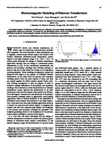
Fig. 1. (Top) Generic time window, window section and subsection plan based on IEEE 802.1Qbv. (Bottom) (a) Reference architecture for the time-aware shaper use-cases presented in this work and (b) Scheduling design concept. SDN: Software-defined networking; SW: Ethernet switch; PTP: Precision-time protocol; BC: Boundary clock; GM: Grand master; PDCP: Packet data convergence protocol; RLC: Radio link control; MAC: Media-access control; PHY: Physical layer
background traffic rates, frame sizes and burst sizes. Further optimization for the model and additional simulation results are presented in Section V, with the paper concluded in Section VI. II. TAS OPERATION PRINCIPLE AND REFERENCE SCENARIO The idea behind the IEEE 802.1Qbv TAS is to define a transmission window within which temporally non-overlapping sections are assigned to the different traffic flows. Thus, timereferenced transmissions occur in unison with the window sections ensuring that the different streams do not contend. The scheduler will only allow a flow to pass through the bridge during its assigned section. In effect, the scheduler “gates” the port queues according to the current window section (or subsection). Obviously, a prerequisite to implementing this TAS is to have an overlaid time synchronization network as both endstations and switches will need a common time reference. The end-stations need to be aware of the time window plan in the switch so that they can arrange their transmissions. On the other hand, the switch scheduler needs to be aware of the characteristics of the different traffic sources and resize its window sections accordingly. The division of the overall transmission time (i.e. encompassing all traffic sources) into the different window sections is shown in Fig. 1 (top). High priority traffic (HP) is assigned to a protected window section (PS) within which subsections (PSS) can be assigned to the different HP flows. Similarly, a best effort section (BES) is assigned to the lower priority traffic (LP) which can be subdivided into subsections (BESS) for individual LP flows. Maximum protection for the HP traffic is provided by employing a guard period (GP)
between the BES and PS, where transmissions are not allowed, ensuring that LP traffic does not overun into the PS. An example reference scenario showing the TAS use-cases considered within this work is shown in Fig.1 (a) (bottom). The TAS is applied towards the edge of the mobile network where fronthaul networks are formed. The fronthaul is made up of digital unit (DU) pools that are connected through Ethernet links to remote units (RU). Some of the RAN processing is carried out in nodes that are closer to the core (here for example nodes that implement a PDCP/RLC interface split are shown). The DUs then perform the rest of the LTE processing up to (and including) the LTE MAC layer. MAC/PHY split data flows are then transported to the RUs (which perform the PHY layer processing) over the fronthaul links. At the same time, timing flows (e.g. PTP) are provided over the fronthaul through the use of PTP boundary clocks (PTP BC). Local and global scheduling over the TAS application area is provided though scheduling entities (for example SDN-type controllers). The global scheduler communicates configuration parameters, between the switch and the end-stations, regarding window section configurations (these configuration parameters and the window section design aspects are discussed further in Section III). III. TIME-AWARE SHAPER IMPLEMENTATION In this section, the TAS model design and its implementation in Opnet are presented, together with an initial result for operational verification. Note, throughout the rest of the paper, the term “packet” may be used instead of “frame”,
with both terms used interchangeably to describe an Ethernet frame. The duration of the windows should enable the accommodation of the generated traffic in every TW. The size of the PS (or PSS) in the switch, Ws_p, can be calculated according to ��_� = ∑���
�� �
�
+ � + �� + 2�,
(1)
while the PS in the end-station, We_p, is given as ��_� = ∑���
�� �
�
+ � + 2�,
(2)
where N is the total number of packets sent in the PS, R (bits/s) is the output interface link rate, Pn (bits) is the packet length, Dp (s) is the propagation delay, In (s) is the inter-frame gap and D (S) is a factor that takes into account the time drifting (or timing instability) in the section boundaries and/or packet generation times in the application within the end-station. Note that the first term inside the parentheses represents the serialization delay of the frame. Fig. 2 shows how the PS duration in the switch and endstation is set-up according to (1) and (2); the only difference is the inclusion of the propagation delay from the end-station to the switch. Then, the best effort section duration WBE, is given by ��� = �� − ���������� − � ! ,
(3)
where TW is the transmission window duration and WGP is the duration of the guard period. The simulation setup in Opnet is shown in Fig. 3. Two traffic generators are used, one representing the HP traffic source (TG1) and the other representing the LP traffic source (TG2). These are then assigned to the PS and BES respectively by the TAS. The TAS is implemented in the output ports of the endstations and the input ports of the switch as shown in Fig.3, through port gating.
Fig. 3. TAS implementation in Opnet. TG1 generates the HP traffic while TG2 the LP traffic
If an HP packet is received in the input port A of the switch, the scheduler will allow the traffic to go through to output port C, only if it is received within the PS (given by the time limits t2 and t1) which has a length given by t2-t1. If the packet is received outside these time limits, it will be dropped. After time t2, port A will be blocked and port B will become unblocked for a duration given by t3-t2 (where t3 is the time limit for the best effort section) allowing the LP packets received in port B to be passed through to the output port C. The algorithm implementation in the switch is shown in Fig. 4. First, PS and BES boundaries for the current TW are initialized based on the window design parameters described by (1) and (2). Once the section boundaries are initialized, the switch medium access control (MAC) layer checks whether any received packet coming from the input port is received within the section that has been allocated to this source. If the packet is being received within its allocated section, the switch will allow it to pass through to the output port, otherwise it will be dropped. Finally, the algorithm checks whether the current TW is expired; if it has, it updates the sections for the new TW. Note that the section boundaries for the new TW can be different, allowing the scheduler to accommodate changes in the traffic characteristics. 1 2 3 4 5 6
7
"#$#%&#'( *+,$(-$(. /(-$#," $#0( 1,2".+#(3 �1, �2, �3, … . �" ; {�9 , P; , �, I" } "#$#%&#'( =(3$ >??,+$ /(-$#," $#0( 1,2".+#(3 {�� − A�1, �2, �3, … . �"B} ; {�9 , P; , �, I" } D-E ?+%0( ?+,0 $ℎ( 9ℎG3#-%& &%G(+ HIJKLMN; OM A L-2++("$ $#0( < �QN&& L-2++("$ $#0( > �Q − 1NB TUVW_XY_Z[\][\_^[U[ULMN; OM A L-2++("$ $#0( > �Q N&& L-2++("$ $#0( < �"B _`Y]_K`abULMN; Else OM A L-2++("$ $#0( > �Q N&& L-2++("$ $#0( > �"N c9.%$( /(-$#,"/3213(-$#," $#0(3 �1 = �1 + �". ; �2 = �1 + �". Repeat from step 1
Fig. 2. Durations of the HP sections in (a) the end-station and (b) the switch Fig. 4. Implemented algorithm for the scheduler in the switch in Opnet
The algorithm in the end-stations is shown in Fig. 5, and it is similar to that in the switch with one important difference: LP packets received in the MAC layer from the upper layers will be queued and sent as soon as the BES occurs. Thus, the algorithm bases the TW design on the requirements of the HP traffic source(s); i.e., section boundaries in the end-stations and switch are set according to HP traffic characteristics. The latency, Ln, experienced by packet, n, within the network is measured between reference points R1 and R2 (see Fig. 3). The equivalent simulation-generated timestamps at these two points correspond to the time that a packet is fully serialized out of the traffic generator output port up to the time the same packet is fully serialized out of the switch 2 output port. The average frame delay variation (FDV) is then given as l
gggggg = ∑ mn|i �i jk |, e�f ���
(4)
An initial set of results is obtained to demonstrate the portgating operation in the switch. Here, both traffic generators have the same transmission pattern (i.e. start and end their transmissions at the same time), frame size and data rate while both sources are constant-packet rate ones. The inter-repetition time for both is set to 800 µs while the TW is set to 1.6 ms with the PS section (allocated to TG1) occurring from 0-800 µs, followed by the BES. Fig. 6 shows the transmitted traffic originating from TG1 and the traffic that is sent by Switch 1 to the trunk. As there is an arbitrary defined propagation delay from end-station to switch, frames that are transmitted at the end of their section in the endstation are dropped by the switch scheduler. For example, the sent frame at t=0.0008 s is dropped as it arrives outside the PS in the switch while the frame sent at t=0.0016 s is allowed by the switch to pass through. A summary of the results is shown in Table. I. The TAS completely resolves any contention in the network thereby resulting in zero queuing delay variation. Note that there is no change in FDV as all sources produce traffic with constant parameters (i.e. there is no statistical variation and packets from both sources contend in the same way in every TW).
5
"#$#%&#'( *+,$(-$(. /(-$#," $#0( 1,2".+#(3 �1, �2, �3, … . �" ; {�9 , P; , �, I" } "#$#%&#'( =(3$ >??,+$ /(-$#," $#0( 1,2".+#(3 {�� − A�1, �2, �3, … . �"B} ; {�9 , P; , �, I" } D-E ?+%0( ?+,0 $ℎ( 9ℎG3#-%& &%G(+ HIJKLMN; opOqU A L-2++("$ $#0( < �QN&& r "92$s2(2( = ! "2&&u && L-2++("$ $#0( < �Q + 1NB TUVW_XY_Z[\][\_^[U[ULMN; OM A L-2++("$ $#0( > �Q N&& L-2++("$ $#0( < �"B
6
Else
1 2 3 4
7
vVwU`\_K`abU_vV_vV][\_^[U[ULMN;
OM A L-2++("$ $#0( > �Q N&& L-2++("$ $#0( > �"N c9.%$( /(-$#,"/3213(-$#," $#0(3 �1 = �1 + �". ; �2 = �1 + �". Repeat from step 1
Fig. 5. Implemented algorithm for the scheduler in the end-station in Opnet
Fig. 6. Transmitted traffic in the protected window by TG1
TABLE I.
DELAY, FDV, QUEUING DELAY AND QUEUING DELAY VARIATION FOR THE RESULTS OF FIG. 6
Applied Technique
Traffic Source
FDV (µs)
Delay (µs)
Queuing Delay (µs)
One Traffic at a time (Base line)
TG1
0
34.51
0
Queuing Delay Deviation (µs) 0
TG2
0
34.42
0
0
Protected (TG1) Best Effort (TG2) TG1 TG2
0
34.51
0
0
0
34.42
0
0 0
38.98 34.42
2.162 2.162
With TAS
Without TAS
4.25
IV. SIMULATION RESULTS Two sets of results are presented here. They are used to show the performance of the TAS with high priority traffic emulating that produced by the precision-time protocol (PTPv2). TG1 represents a PTP BC that generates 32 sync messages per second per PTP slave, while TG2 represents a source of LTE MAC/PHY split traffic. The number of PTP slave stations are 50 (note that these are modelled through the amount of traffic generated and the corresponding utilization in the trunk and not as separate receivers) and each sync message is formed as a 68octet packet. The FDV results presented here for the TAS are compared to the baseline case, that of strict priority scheduling. A. Variable burst size The LP traffic for this scenario will be bursty with a varied burst size and constant frame size. The variation in the burst size in this case emulates a traffic stream that would be produced from the implementation of a MAC/PHY split where the number of users serviced in a cell (i.e. the cell load) varies from one LTE transmission time interval (TTI, 1 ms) to the next. Thus, the packets here represent LTE MAC transport blocks (TBs) encapsulated by Ethernet. The TG2 traffic burst size varies between 1 and 10 frames, following a uniform distribution. The
frame size in each burst is 1000 octets (excluding headers) and the interframe gap is 2,000 bits, corresponding to a duration of 2 µs. Based on (1), and assuming a timing drifting factor D, equivalent to 4% of the TW, the PS is set to 50 µs. The GP is allowed to vary from zero to the value of the serialization delay of a LP frame. Fig. 7 shows the peak and average FDV results for TAS with different GPs and for SP. The worst-case performance for TAS, i.e. with zero GP, is equivalent to the SP performance. This is expected, as any ongoing transmission would force an HP packet to wait until the end of transmission in both cases. The step-like behavior is attributed to the constant TW duration, which means that every time the GP is increased the BES duration is reduced. As a result, a change in the FDV will not occur until the BES section is reduced by an amount that results in a packet being excluded by the window section. This can also be seen by the fact that the sum of the peak FDV value and the guard period, whenever a step change occurs, is approximately equal to a full serialization of an LP frame. As the GP is increased, both the average and max FDV with TAS reduce steadily until they reach zero at a GP of 8 µs. This value corresponds to a full serialization of a LP packet.
Fig. 8. Average and peak FDV for the PTP traffic with SP and TAS with different GPs. The background traffic source is bursty with variable frame size
B. Variable frame size In this case, the frame size is allowed to vary between 100 and 1500 octets within the burst, following a uniform distribution, while the burst size is constant (10 frames). The results for this scenario are shown in Fig. 8. It can be seen that even with a variable frame size for the LP flow, the TAS can eliminate the FDV. For these results specifically, zero FDV for the HP packets is achieved with a GP of approximately 85% of the maximum LP frame serialization delay.
The first is to drop the frame. This can work for PTP traffic but other HP streams such as MAC/PHY split primitives for example, should not be dropped. These primitives can consist of downlink control information and user-specific configurations for the LTE PHY layer in the RU. Dropping a frame then, may result in the user allocations for a whole LTE subframe (1 ms TTI) being lost. Another option is to enable buffering protection and thus buffer the frame(s) that are received outside the HP section and transmit them in the next TW. Note that specifically for PTP packets, the PTP algorithm in the slave stations will have to handle the resulting sudden timing updates on the order of the TW duration, either by ignoring them or by applying a correction factor equivalent to the TW duration (i.e. the FDV will be otherwise unchanged).
V. BUFFERING PROTECTION
The PS duration, Ws_buf, in the switch has to be modified to accommodate the buffered frames and will be given as
It is conceivable that in certain cases the time drifting factor D, will be exceeded. This can be a result of limited provisioning in order to reduce the end-to-end latency of the fronthaul. There are two solutions for this.
Fig. 7. Average and peak FDV for the PTP traffic with SP and TAS with different GPs. The background traffic source is bursty with variable burst size and constant frame size
��_xyz = ∑���
�� �
�
+ � + �� + � + max (�, /~ ),
(5)
where SK is the serialization of up to K frames that have been buffered from the previous TW. Note that the change in the PS duration will depend on the size of the buffered frames. For very small frames, the variability factor D might be large enough to accommodate the transmission of the buffered frames (this is taken into account by the max term in (5)). Fig. 9 shows the changes in the PS design with buffering protection. Note that although not shown here, the same change is required in the PS duration at the end-station. The modified PS duration is applied only for the TWs for which buffering has occurred. The local scheduler will check its buffer and determine whether it needs to modify the PS boundaries for the next TW (and to communicate the modifications to the switch through the global scheduler). Otherwise, if buffering has not occurred, the normal PS configuration is applied. Fig. 10 shows the result of not provisioning the PS duration to take into account buffered frames. For this result, the encountered time drifting exceeds D and is such that a single frame is buffered. If the PS duration is not modified according to (5), then for every subsequent TW a new frame (or more than one frame) will be buffered.
REFERENCES [1] [2]
[3] Fig. 9. PS duration definition with buffering protection [4]
[5]
[6]
[7] [8]
[9] Fig. 10. Comparison of frame delay results with buffering protection, with and without the modified PS design shown in Fig. 9
[10] [11]
However, with a modification according to (5), the frame delay drops to the expected value in the next TW. VI. CONCLUSION An Opnet model implementation for the time aware shaper (TAS) based on the IEEE 802.1Qbv standard was presented. A number of use cases were used to show the performance of the TAS and compare it with the performance of the SP regime. The use-cases are based on a reference architecture and focus on the network-edges of next generation radio-access networks where timing flows (based on the precision-time protocol) and LTE functional split flows are envisioned to exist. The design of the TAS windows takes into account timing instability that is expected to result from the move to software-defined fronthauling while a special case of buffering protection for the high-priority traffic is also presented. The simulation results show that the TAS is capable of minimizing the contentioninduced frame-delay variation for the high-priority traffic, while provisioning a guard period based on the maximum serialization delay of a low-priority frame can lead to a complete removal of FDV. ACKNOWLEDGMENT Data used in this work is stored in Kent Academic Repository (https://kar.kent.ac.uk/).
[12] [13]
[14]
iCIRRUS (July 2015), “D2.1: iCIRRUS intelligent C-RAN architecture,” [Online]. Available: http://www.icirrus-5gnet.eu/category/deliverables/ iCIRRUS (Jan. 2016), “D3.1: Verification of Ethernet as transport protocol for fronthaul / midhaul,” [Online]. Available: http://www.icirrus5gnet.eu/category/deliverables/.. N.J. Gomes, V. Jungnickel, P. Chanclou, J.-P. Elbers, and P. Turnbull, “A flexible, Ethernet fronthaul for 5th generation mobile and beyond (Invited),”, in Optical fiber Commun. Conf. (OFC), 2016, Anaheim, CA, 2016, paper W3C.1. U. Dötsch et al, “Quantitative analysis of split base station processing and determination of advantageous architectures for LTE,” in Bell Labs Tech. J., vol. 18, no. 1, pp. 105-128, June 2013. NGMN (Mar. 2015), “A deliverable by the NGMN alliance: Further study on critical C-RAN technologies”. Available: https://www.ngmn.org/publications/technical.html. 3GPP, “Study on New Radio Access Technology; Radio Access Architecture and Interfaces (Release 14),” 3GPP TR 38.801 V0.4.0, Aug. 2016 [Online]. Available: http://www.3gpp.org/DynaReport/38series.htm. “Next Generation Fronthaul Interface” IEEE 1914 Working Group [Online]. Available: http://sites.ieee.org/sagroups 1914 iCIRRUS (Jul. 2016), “D3.2: Preliminary Fronthaul Architecture Proposal,” [Online]. Available: http://www.icirrus5gnet.eu/category/deliverables/. "Enhancements for Scheduled Traffic," IEEE standard 802.1Qbv [Online]. Available: http://www.ieee802.org/1/pages/802.1bv.html. “Frame Preemption," IEEE standard 802.1Qbu [Online]. Available: http://www.ieee802.org/1/pages/802.1bu.html. “Time-Sensitive Networking for Fronthaul,” IEEE Standard P802.1CM [Online]. Available: http://www.ieee802.org/1/pages/802.1cm.html CPRI (Oct. 2015), “CPRI Specification V7.0, Interface Specification,” [Online]. Available: http://www.cpri.info/spec.html. T. Wan, P. Ashwood-Smith, “A Performance Study of CPRI over Ethernet with IEEE 802.1Qbu and 802.1Qbv Enhancements,” in Global Commun. Conf. (GLOBECOM), San Diego, CA, 2015, pp. 1-6. M. K. Al-Hares, P. Assimakopoulos, D. Muench and N. J. Gomes, “Scheduling in an Ethernet Fronthaul Network,” in Eoropean Conf. on Networks and Commun. (EUCNC), Oulu, Finland, 2017. Accepted for publication.