Abstract: In this panel contribution, the modeling of wind turbines in power systems dynamics simulations is discussed. First the three most important actual wind ...
Modeling Wind Turbines in Power System Dynamics Simulations J.G. Slootweg’
S.W,H, de Haan2 Member,
H. Polinderz
IEEE
Member,
IEEE
W.L. Kling’ Member,
IEEE
1 Electrical Power Systems, 2 Electrical Power Processing
Faculty of Information Technology and Systems, Delft Umversity of Technology P.O. Box 5031, 2600 GA Delft, The Netherlands Phone: +31 152786219, Fax: +3 I 152781182, e-mail: j,g.slootweg@Jits. tudelft.nl
Abstract: In this panel contribution, the modeling of wind turbines in power systems dynamics simulations is discussed. First the three most important actual wind turbine concepts are described. Then, various classes of wind turbine models are introduced and it will be discussed which model type can be integrated in power system dynamics simulation software. To conclude, it will be argued that it is possible to model various kinds of variable speed wind turbines with only one model in power system dynamics simulations.
electrical power system and their interaction with other generation equipment and with loads. In this panel contribution, first the three most important actual wind turbine concepts are described. Then, various classes of wind turbine models are introduced and it will be discussed which model type can be integrated in power system dynamics simulation software. Such a model can be used to investigate the interaction of wind turbines with other generation equipment and with loads within the framework of power system dynamics studies. To conclude, it will be argued that it is possible to model various kinds of variable speed wind turbines with only one model in power system dynamics simulations.
Keywords: wind tmrbine, modeling, simulation, power system dynamics, grid integration I. INTRODUCTION
II. THREE MOST IMPORTANT ACTUAL WIND TURBINE CONCEPTS
As a result of increasing environmental concern, the impact of conventional electricity generation on the environment is being minimized and efforts are made to generate electricity flom renewable sources. The main advantages of electricity generation from rtmewable sources are the absence of harmtirl emissions and the infinite availability of the prime mover that is converted into electricity. One way of generating electricity from renewable sources is to use wind turbines that convert the energy contained in flowing air into electricity. Up to this moment, the amount of wind power integrated into large scale electrical power systems only covers a small part of the total power system load. The rest of the power system load is for the largest part cc,vered by conventional thermal, nuclear and hydro power plants. Wind turbines often do not take part in voltage and frequency control and if a disturbance occurs, the wind turbines are disconnected and reconnected when normal operation has been resumed. Thus, notwithstanding the presence of wind turbines, frequency and voltage are maintained by controlling the large power plants as would have been the case without any wind turbines present. This is possible, as long as wind power penetration is still low. However, a tendency to increase the amount of electricity generated from wind turbines can be observed. Therefore, the penetration of wind turbines in electrical power systems will increase and they may begin to influence overall power system behavior, making it impossible to run a power system by only controlling large scale power plants. It is therefore important to study the behavior of wind turbines in an
0-7803-7173-9/01/$10.00 © 2001 IEEE
A. Squirrel cage induction generator
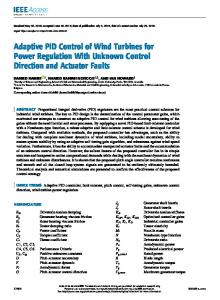
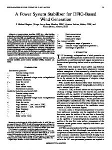
The first concept is a grid coupled squirrel cage induction generator. This concept consists of a rotor coupled to a squirrel cage induction generator through a gearbox. The gearbox is needed, because the optimal rotor and generator speed ranges are different. The generator is directly grid coupled. Therefore, rotor speed variations are very small, because the only speed variations that can occur are changes in the rotor slip. The order of magnitude of these speed changes is in the per cent range. Because speed variations are very small, the turbine is normally considered to operate at constant speed. A squirrel cage induction generator consumes reactive power. Therefore, in case of large wind turbines and/or weak grids, often capacitors are added to generate the induction generator magnetizing current, thus improving the power factor of the system as a whole. The power extracted from the wind needs to be limited, because otherwise the generator could be overloaded or the pullout torque could be exceeded, leading to rotor speed instability. In this concept, this is oflen done by using the stall effect. This means that the rotor geometry is designed in such a way that its aerodynamic properties make the rotor eftlciency decrease in high wind speeds, thus limiting the power extracted from the wind and preventing the generator ffom being damaged and the rotor speed from becommg unstable. Thus, during normal operation of a stall regulated
22 0-7803-7031-7/01/$10.00 (C) 2001 IEEE
factor, thus not taking part in the reactive power exchange between the turbine and the grid. In this mode of operation, rotor current control enables full active and reactive power control. Active power is controlled in the following way. With a frequency of about 20 Hz, an electrical power set point is generated, on the basis of the actual rotor speed and using the rotor speed versus power control characteristic. From this, a torque set point is calculated, again taking into account he actual rotor speed. Using this torque set point and a number of other parameters, the required rotor current is calculated. Because the mechanical rotor frequency and the stator frequency differ, a three phase voltage is induced in the rotor winding. Through the converter, a three phase current with the same frequency and the calculated amplitude is fed into the rotor winding. The generator and converter are prevented from being overloaded in high wind speeds by controlling the back-toback voltage source converter in such a way that the nominal power of generator and converter is not exceeded. However, when the wind speed increases, the mechanical power extracted from the wind increases as well if no countermeasures are taken. This would make the rotor speed increase because mechanical power becomes higher than electrical power. To limit the rotor speed, the blades are pitched, thus reducing the mechanical power extracted from the wind and restoring the balance between mechanical power and electrical power. In this way, the rotor speed is prevented from becoming too high. Thus, in contrast to the last concept described, this concept is equipped with pitch control.
Rotor Squirrel cage induction
‘earbow Compensating capacitors k
Figure 1. Grid
couple(i squirrel
cage induction
generator
wind turbine no controller sareactive. This system concept is also known asthe'Danish concept' andisdepicted in figure 1. B. Doubly fed indiiction generator
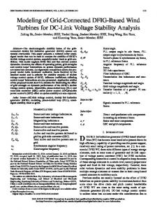
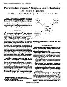
The second concept is a wind turbine with doubly fed (wound rotor) induction generator in which a back-to-back voltage source converter feeds the rotor winding. Like in the former concept, a gearbc~x is necessary to couple the rotor to the generator, because of the difference in the rotor and generator speed ranges. The stator winding of the doubly fed induction generator is coupled to the grid, the rotor winding is coupled to a back-toback voltage sourt;e converter. The other side of the converter that feeds the rc,tor winding is coupled to the grid. The converter decouples the electrical grid frequency and the mechanical rotor frequency, thus enabling variable speed operation of the wind turbine. The sum of the mechanical rotor frequency, multiplied by the number of pole pairs, and the electrical rotor frequency equals the grid frequency applied to the statm. The system is depicted in figure 2. Normally, the converter has current control loops. The ability to control the rotor current substantially contributes to the controllability of the wind turbine, because when the stator resistance is neglected, the electro mechanical torque and stator reactive pclwer are dependent on the quadrature and direct component of the rotor current respectively. The grid side of the converter is normally operated at unity power Rotor
C. Direct drive synchronous
generator
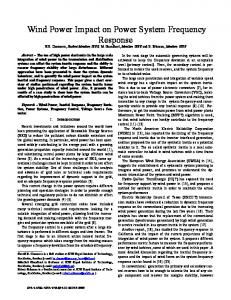
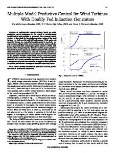
The third important contemporary wind turbine concept is the direct drive synchronous generator. In this concept, the rotor is directly coupled to the generator and no gearbox is needed. The system is depicted in figure 3. The synchronous generator is a ring generator with a large number of poles. In view of the low mechanical frequency, it is necessary to use a ring generator to achieve an acceptable generator weight for the desired power rating. The stator winding of the direct drive synchronous generator is coupled to voltage source converter or a diode rectifier. When a back-
Doublyfed (woundrotor) induction generator
Rotor Grid
Gear box
u
Converter Grid
u, Converter IF
‘~“
1,
I,
Q
“
() ‘d
+
Figure 3. Direct drive synchronous generator grid coupled through a back-to-back voltage saurce canverter or a diade rectifier and vollage source converter
Figure 2. Doub[yfed (wound rotor) induc[ion generator with back-toback voltage source converter feeding the rotor winding
0-7803-7173-9/01/$10.00 © 2001 IEEE
23 0-7803-7031-7/01/$10.00 (C) 2001 IEEE
to-back voltage source converter is used, the generator torque is controlled by changing the stator currents through controlling the generator side converter voltage. When a diode rectifier is used, the generator is controlled indirectly by controlling the DC link voltage using the voltage source converter at the grid side. Because a voltage source converter is self-commutated, reactive power can both be generated and consumed by the grid side of the converter by injecting a leading or lagging current. Thus, the current on the grid side of the converter is controlled in such a way that the generator real power is transferred to the grid and the terminal voltage (nearly) equals a reference value. Like the variable speed wind turbine with doubly fed induction generator, this concept enables full active and reactive power control. In high wind speeds the generator power is again limited to protect both the generator and the converter, resulting in an unbalance between mechanical power extracted from the wind and generated electrical power. This leads to an increase in rotor speed, which needs to be limited. This is again done by pitching the blades. Like the former concept, this concept is equipped with pitch control.
The only way they can be used for power system dynamics simulations is by modeling the wind turbine as a wind speed signal or measured wind speed sequence combined with a controllable power source. The power curve can then be used to calculate the amount of generated power at a certain wind speed. This will however result in inaccuracies in the case of variable speed wind turbines. A model of this kind can be used for investigating slow voltage fluctuations at some point in the network or the reaction of other generation equipment to the fluctuations in wind turbine power output. It can, however, not be used for the simulation of grid faults, neither in the case of constant speed wind turbines, because the squirrel cage induction generator reacts to changes in grid frequency or voltage, nor in the case of variable speed wind turbines, because in these turbines the power electronics controllers will react very quickly if voltage and frequency changes exceed certain limits and have therefore to be modeled as well. C. Subtransient
III. CATEGORIES OF WIND TIJRBINE MODELS A. Introduction
In this section, various categories of wind turbine models will be discussed. Only the electrical part of the wind turbine is considered, the mechanical part is not taken into account. Therefore, the distinction between the model categories is based on the modeling of the electrical part of the wind turbine. Each model category can be combined with various representations of the mechanical ]part, reaching from an algebraic relation between wind speed and mechanical power combined with a lumped mass representation of the shaft and the rotor, to a detailed high order dynamic model of the rotor, the shaft and if applicable the gearbox, in which the blade element method is used to calculate the mechanical power extracted from the airflow. B. Models based on wind turbine power curves
The first kind of wind turbine models is formed by models that are based on the wind turbine power curve. This kind of model is mainly used for calculations of the energy that a wind turbine will produce if erected at some site. This value then can further be used for calculations concerning the financial performance of the envisioned project. Normally hourly or half hourly measured wind speed values measured during a long time period are used for these calculations. Models of this kind are not adequate for power system dynamics simulations, because they do not contain any equations describing the dynamic behavior of the wind turbine or its interaction with the grid. Further, they do not take into account that in the case of variable speed wind turbines, the power generated at a certain wind speed not only depends on the wind speed, but on the actual values of rotor speed and pitch angle as well.
0-7803-7173-9/01/$10.00 © 2001 IEEE
models
The second kind of wind turbine models are subtranslent models. A constant speed wind turbine model of this kind would consist of some model of the mechanical part, from which for a certain wind speed the generator mechanical power or torque results. This value then must be applied to a subtransient model of a squirrel cage induction generator. Such an induction generator model has at least five states, namely stator and rotor fluxes in the d- and q-axis and the mechanical speed. The smallest time constant in this model is in the range of 10 ms, depending on generator size. If a constant time step is used for the simulations, it should be a number of times smaller than this time constant, depending on the integration algorithm used in the calculations and therefore be equal to about 1 ms. The first part of subtransient models of variable speed wind turbines again consists of a conversion from wind speed to mechanical generator power or torque. Depending on the wind turbine type being modeled, the result is applied to a subtransient model of a doubly fed induction generator, which has at least five states, or a subtransient model of a synchronous machine which has at least five states and if the damper windings are taken into account seven or eight. Further, detailed models of the power electronic converters are needed, including the semiconductor switches. Both the current control loops of the power electronic converters and the higher level controllers controlling generator torque and real and reactive power injected in the grid must be modeled. The switching frequency of power electronic converters used in wind turbines varies tlom above 10 kHz for small wind turbines to about 1 kHz for larger ones. The smallest time step should be a number of times smaller than the switching frequency, resulting in time steps in the range of 0.1 ms to 0.01 ms, depending on the size of the wind turbine studied. The following problems complicate the integration of subtransient models in power system dynamics simulation software: . They are complicated, particularly in the case of
24 0-7803-7031-7/01/$10.00 (C) 2001 IEEE
variable speed wind turbines. Advanced knowledge of power electronics and control system theory is necessary to develop and tune the model of the power electronic converter and the controllers. The simulation time step is too small to make these models practically usable in power system dynamics simulations, resulting in the infeasibility of simulation of large power systems with many wind turbines as well as other generation equipment and loads, . The number of parameters required to fully speci$ these models is large, whereas the influence of some parameters on the relevant aspects of wind turbine behavior is small and many of the parameters are not known in the early stages of power system studies. Furthermore, the subtransient models do not comply with an important characteristic of power system dynamics simulation software, namely the modeling of the network using a constant admittance or impedance matrix. This implies that in power system dynamics simulations only fi.mdamental tlequency components are taken into account and subtransient phenomena are neglected. To get a consistent model of the whole power syst:m including the wind turbines, the latter should also im;orporate only fundamental frequency components and no higher harmonics. Therefore, transient or dynamic models hive to be developed.
controlled current sources. This is possible due to the neglect of the d~ldt temns in the voltage equations, because instantaneous current changes do not lead to high overvoltages as would have been the case with the d$/dt terms included. As a result of these simplifications, an algebraic equation between generator torque and rotor current in the wind turbine with doubly fed induction generator and between generator torque and stator current in the wind turbine with direct drive synchronous generator results. This observation enables a last substantial simplification. When an algebraic relation between generator rotor or stator current and generator torque exists, a generator torque set point can be reached instantaneously by injecting the appropriate rotor or stator currents. However, when torque set points can be reached instantaneously, it is not necessary to drag along the equations describing the generator, Instead, the generator can be modeled as a torque source, which immediately generates an amount of torque equal to the set point generated by the controller. An important advantage of this approach is that it opens the way to model both kinds of variable speed wind turbines with one model, a universal variable speed wind turbine model. The differences in behavior of the two generator types used are compensated by the power electronic converters and the controllers and the result is a great similarity with respect to grid interaction for both kinds of variable speed wind turbines, which is the main point of interest in power system dynamics simulations. Note the difference between the models based on the wmd turbine power curve, as described above, and the universal variable wind speed model that results after the simplifications carried out here. In the first case, the behavior of the mechanical part of the wind turbine and the protection system of the power electronic converter are not taken into account. However, the universal variable speed wind turbine model derived here must be combined with an adequate model of the wind turbine rotor including rotor speed control and pitch control, with power factor or grid voltage control and with a model of the protection system of the converter. Otherwise, the resulting model is basically a model based on the wind turbine power curve, which is not adequate for all power system dynamics studies as argued above.
●
D. Transient or d)natnic
models
The third kind of wind turbine models are transient or dynamic models. Starting from a subtransient model, a transient model can be developed in the following way . In the constant speed wind turbine model and in the model of ?, variable speed wind turbine with doubly fed induction generator, the d$/dt terms in the stator voltage equations must be neglected. In the models of the variable speed wind turbines, the grid side of the power electronic converters must be modeled as a controlled voltage source, that is equipped with such a controller that a set point for the grid current is reached within about 10 ms. The above measures solve the inconsistency between the subtransient variable speed wind turbine models and the model ing of the network and the other generators in power system dynamics simulations. However, the three other problems of variable speed wind turbine models, namely the complexity of the models and the small simulation time step and large number of parameters required have not been fully solved yet. Therefore, the following additional simplifications are proposed: . In the model of the variable speed wind turbine with ●
IV. CONCLUSIONS In this panel contribution, the modeling of wind turbines in power system dynamics simulations was discussed. First, the most important actual wind turbine concepts were described Then, various models of each of these concepts were discussed, namely: Models based on the wind turbine power curve, which do not incorporate the wind turbine reactions to
doubly fed induction generator, the d~/dt terms in the rotor volta;~e equations are neglected. .
In the model of the variable speed wind turbine with direct drive synchronous generator, the d*/dt terms are neglected
.
in both
equations. The power modeled
as
the
stator
and
the
electronic
converters
controlled
voltage
0-7803-7173-9/01/$10.00 © 2001 IEEE
rotor
●
terminal voltage and frequency changes and contain inaccuracies in the case of variable speed wind turbines, because they do not take into account actual pitch angle and rotor speed values.
voltage
are no longer sources,
but
as
25 0-7803-7031-7/01/$10.00 (C) 2001 IEEE
However, this model should be combined with an adequate rotor model, a rotor speed controller model, a power factor or grid voltage controller model and a model of the protection system of the power electronic converter, because otherwise an inadequate model comparable to the power curve based models described above would result.
Subtransiect models, including detailed models of the generators, power electronics and controllers, which can not be used in power system dynamics simulations, because they contain high frequency components and fimther have a small simulation time step and their complexity as an additional disadvantage. Transient m dynamic models, which are derived from subtransient models by neglecting the terms that introduce higher harmonics and the switching phenomena and by replacing controlled voltage sources by controlled current sources. Finally, it was concluded that after the simplifications that are necessary to derive a transient model for use in power system dynamics simulations starting from a subtransient model, the differences between the two generator types used in variable speed wind turbines can not be seen in their interaction with the grid anymore, because they are fully compensated for by the controllers. Therefore, it is possible to replace the generator by a controllable torque source, enabling the representation of both variable speed wind turbine types with one universal vari:~blespeed wind turbine model.
o
V. FURTHER READING
●
0-7803-7173-9/01/$10.00 © 2001 IEEE
The following references may be consulted for further information with respect to the topics addressed in this summary: [1] S. Heier, Grid integration of Wind Energy Conversion Systems, Chicester, UK: John Wiley& Sons Ltd., 1998. [2] J.F. Walker, N, Jenkins, Wind energy technology, Chicester, UK: John Wiley& Sons Ltd., 1997. [3] N. Hatziargyriou (cd.), Modeling new forms of generation and storage, CIGRE TF38.O 1.10, Paris, November 2000 [4] V. Akhmatov, H. Knudsen, A.H. Nielsen, Advanced simulation of windmills in the electric power supply, International Journal of Electrical Power& Energy Systems, VO1.22no.6, 2000, pp.421-434.
26 0-7803-7031-7/01/$10.00 (C) 2001 IEEE