Nets [3] (CPNs) have been chosen to model the ODP Trader. ... a server object (exporter) which may be physically located el- ..... Design/CPN User's Manual.
Modelling an Object Based System with Coloured Petri Nets A. Tokmakoff, J. Billington Telecommunications Systems Engineering Centre, University of South Australia, Warrendi Road, The Levels, 5095, Australia Fax: +61 8 302 3873 Tel: +61 8 302 3606 E–Mail:[A.Tokmakoff, J.Billington]@UniSA.Edu.Au Keywords: Modelling, Petri Nets, RM–ODP Trader
Abstract The Reference Model for Open Distributed Processing (RM–ODP) defines an architecture which allows heterogeneous software components to interact, where entities in the system are Objects. In RM–ODP, entire applications may be considered to be Objects. In order to allow dynamic location of services/resources, a Trading function has been defined which is performed by a Trader instance. In this paper, a Coloured Petri Net model of the RM–ODP Trader and its environment is presented. In addition, the software package Design/CPNT used in the modelling of Trader is described in detail.
1. Introduction Object based systems are widely accepted as the underlying model for Open Distributed Systems, as illustrated by the recent standardisation efforts of ISO and ITU–T with the Reference Model for Open Distributed Processing [1] (RM–ODP). Such distributed systems operate across heterogeneous platforms, where hardware and software systems are provided by multiple vendors and aim to share resources and services in a completely transparent and dynamic manner. As part of this work, a Trading function [2] has also been standardised. The Trader is a trusted third party which matches clients with service providers. When modelling systems, the aim is to create a description which improves our understanding, and also allows us to verify properties of the system. With this in mind, Coloured Petri Nets [3] (CPNs) have been chosen to model the ODP Trader. This paper presents a method for modelling distributed object– based systems with Design/CPNT[4], a freely available package 1
which allows the creation of CPN models. The approach is illustrated by a model of the RM–ODP Trader, and features of Design/CPNT are discussed.
2.
The RM–ODP Trading Function
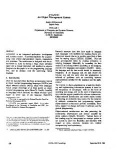
The Trader provides a mechanism which allows objects in a distributed system to locate each other and share resources/services. Thus, a client object (importer) may dynamically locate a server object (exporter) which may be physically located elsewhere in the heterogeneous distributed system using a Trader. Multiple autonomous Traders may interwork [5], thereby increasing the offer space available to client objects and providing a means for information partitioning. The Trader maintains a database of exported service offers and matches an import request with previously exported service offers, returning the most “appropriate” offer to the importing object (based upon initial request criteria). The sequence of interactions between the Exporter, Importer and Trader to locate a service are shown in Fig. 1 [6]. TRADER
3.Import Reply
1.Service Export 2.Import Request 4.Service Invocation 5. Service Reply
Importer Exporter Fig. 1. Sequence of Interactions between Exporter, Trader, and Importer.
1. Service Export: The Trader receives a service export from the Exporter. This request includes a description of the service, and the location of the service provider which may also be the Exporter. This information is stored in a database. 2. Import Request: The Trader receives a service import request from a client. This request includes the type of service required and a list of desired attributes. The Trader checks with the Type Repository (not shown in Fig. 1) to ensure that the requested service and properties are legal. 3. Import Reply: The Trader searches its database of exported services and returns any successful matches after applying selection criteria if requested by the Importer. This includes service location information. 4. Service Invocation: The Importer now interacts with the Exporter directly to invoke the service. 2
5. Service Reply: vice request.
3.
The Exporter replies to the Importer’s ser-
Coloured Petri Nets
CPNs were developed in the early 1980’s by Kurt Jensen at Aarhus University in Denmark. CPN models have a graphical form, and a well–defined semantics which allows for formal analysis. They have been applied to a variety of applications including Description of Services in Intelligent Networks [7], Modelling and Analysis of the Remote Procedure Call protocol in the Object–oriented language BETA [8], Specification and Verification of Telecommunication Protocols [9] and Design and Validation of Hardware at the Register level [3]. Graphical simulations may be executed where the modeller observes tokens moving throughout the system as transitions fire. As tokens may be defined as arbitrarily complex data values, the simulation allows data flows to be modelled. CPNs are high level Petri Nets which provide for modelling with hierarchical structure and representation of complex data types. A CPN is composed of the following: D Colour Set: Analogous to a “type” in a Programming Language. D Places: Represented by ellipses, which are typed (thus being of a certain colour). D Transitions: Represented by rectangles. D Arcs: Represented by arrows, which define relationships between places and transitions. D Tokens: Data values contained in places (consistent with the place’s Colour Set). D Inscriptions: Arcs and transitions may be inscribed with expressions containing constants, variables and functions. In the computer support tool, Design/CPN, these are written in Standard ML (SML), a functional programming language. D A set of declarations, defining Colour Sets and functions and declaring variables and constants. The association of tokens with places in the CPN is known as the marking (or global state) of the CPN which is changed by the occurrence of transitions. Variables occur in CPN inscriptions. For a particular binding to variables, if all the input places of a transition have tokens of the required number and colour (as defined by the arc inscriptions), and the transition inscription (guard) is TRUE, then the transition is said to be enabled. More than one transition may be enabled at once. A transition that is enabled may fire. When a transition fires, tokens are removed 3
from the input places and added to output places, as indicated by the arc inscriptions. Design/CPNT supports hierarchical modelling. This means that a model may be spread out over a number of “pages”, where each page models different aspects of the system allowing modularity. A page which is “used” by another is known as a sub–page of the super–page. The CPN on the sub–page is known as a sub–net. The main construct for this is a substitution transition.
4.
Design/CPN
Design/CPNT is a package of tools which support the construction, simulation and analysis of CPNs. It was originally developed in 1989 by Meta Software Corporation in close co–operation with researchers at Aarhus University, Denmark and has undergone continual refinement since that time. It is to be released into the public domain (April 1996) at Version 3.0. There are three main components to the Design/CPN system: an Editor, a Simulator and an Occurrence Graph Analyser (OGA). All three components have been seamlessly integrated into a system which allows the designer to take a system from concept to a formally verified specification. The editor is used to create CPN models. Places, transitions, arcs, inscriptions and declaration nodes are all created in the editor. In addition, it provides features which allow graphical “sugar” to be added to a model, thereby improving readability. Having created a model in the editor, the simulator is then used to test the model. The simulator may operate in interactive mode (graphical feedback), where tokens are seen to “move” throughout the system, or in automatic mode, where a simulation is run until the user–specified terminating conditions are met. Place markings may be modified, and specific transitions may be selected for firing as a means to “debug” the model. When the designer believes the model to be complete, formal analysis may be performed using the OGA. This tool creates a “state space” description of the model, based upon an initial marking. The state space may then be traversed, and properties of the model determined such as the presence of deadlocks, livelocks and unwanted states as defined by the informal specification of the system.
4.
Modelling the RM–ODP Trader
The Page Hierarchy of the model and the top level Trading Environment page will be explained. The model contains an 4
additional 14 pages which due to space limitations, cannot be covered in detail by this paper.
A. The Model Hierarchy Design/CPN provides us with the opportunity to create a hierarchy of nets which as a whole, model the Trader. These nets may represent objects which exist in the Trading Environment, or may be used to hide complexity within the model. Fig. 2 shows the Hierarchy page (Hierarchy#1001 where #1001 refers to the page number) of the model, where pages in the model are designated by a node. Relationships between pages are indicated by a directed acyclic graph. This page indicates a “uses” relationship between pages and is created by Design/CPN upon request (page names are truncated to 8 letters). The function of the pages is given below.
Fig. 2. The Hierarchy page of the Trader Model.
D Declarat#2 is a page which contains the Global Declaration Node, where all colour sets (types) and variables are declared and SML function code for the model is located. D Trad_Env#1 is the top–most page of the model which defines a topology for communication between objects in the Trading Environment. It is also the “Prime” Page which specifies which pages of the CPN should be simulated. D Trad_Int#11 is a page which represents the Trader and the interfaces which it presents to the outside world. It has page references to five (5) sub–pages which represent Inter5
faces. In addition, it contains a page reference to the Trader itself (Trader#12). D Exporter#4 represents the Exporting Object. The model assumes that valid Export Offers have been submitted by this Object and have been stored in the Offer Space Object. D Importer#5 represents the Importing Object. This page models an importing object which submits an Import request to a Trader. D Search#6 represents the Search Policy Object. This Object is used to determine the Search Scope when an Import Request is being processed. The search scope dictates whether a Trader should search the local database, forward the Import Request to linked Traders, or both. D Offer_Sp#7 represents the Offer Space Object which is used by the Trader to manage the offers which are submitted to it by Exporting Objects. It is a Generic Service Object which may be used by any Trader to store Offers. D Link#9 represents the Link Space Object which manages the Trading Links. It maintains a record for each Trader in the Trading Environment, indicating whether the Trader should be used for Interworking. D Trader#12 represents the Trading Object which has page references to both the Import and Export Operations (Import_O#3 and Export_O#10) D TSI_Page#8 represents a Trading Service Interface (TSI). D OSI_Page#13 represents an Offer Space Interface (OSI). D TMI_Page#14 represents a Trading Management Interface (TMI). D SPI_Page#15 represents a Search Policy Interface (SPI). D LSI_Page#16 represents a Link Space Interface (LSI). D Import_O#3 and Export_O#10 model the operations which the Trader performs when servicing an Import and Export Request respectively. These pages are sub–pages of Trader#12.
B. Trader Environment Top Level Page The top level page of the model is Trad_Env#1 (Fig. 3). It can be seen that are seven instances of Computational Objects in the distributed system, each of which has been modelled at a lower level on a separate page. These sub–pages are linked to Trad_Env#1 through the use of a shared place which models the Communication Medium used by objects for message passing. Each object in the system is modelled by a substitution transition which encapsulates the object and places it in the context of the environment in which it resides. Substitution 6
transitions are indicated by the presence of HS located near each transition on the page. The objects communicate through input/output ports which have a mapping from the high–level Trader Environment page to the corresponding sub–page which represents the object. Thus, the place “Comms_Medium” has a place in each substitution transition sub–page which has exactly the same marking.
Fig. 3. The Top Level page (Trad_Env#1).
An important Colour Set in the model is Message which defines the structure of the messages passed between objects in the system. It is defined as a tuple of two colours: color Message = product Addresses*Data;
where Addresses and Data are defined as: color Addresses = product Id*Id; color Data = product Operation*Op_Data;
Addresses is a pair of sender and receiver identifiers for the message, and Data is a pair containing an Operation to be performed and Operation Data, which are parameters for the operation. Objects in the system have unique identifiers required by the communications sub–system to allow inter–object communications. These identifiers are defined by Colour Set Id which is similar to an enumerated type found in most programming languages.
5.
Current Status and Future Work
The Trader has been modelled in [10], where a single TSI was used for all communication between a Trader and external Objects. In this paper, multiple Traders may use multiple TSI’s, thereby allowing concurrent servicing of requests and Inter7
working. In addition, the internal structure of the Trader has been altered to distinguish between concurrently serviced requests. This model is complete and ready to undergo analysis with the OGA tool which will allow us to detect any deadlocks and unwanted states. It is recognised that the state space of the Trading System will be large. It is therefore intended to “port” the model into TORAS, an analysis tool which has advanced techniques for reducing the state space of the model.
6.
Conclusions
In order to verify the correctness of the emerging standard, a model has been created which is formally verifiable and executable through simulation runs. This allows us greater understanding of the system, and increases our confidence in an implementation. CPNs are an appropriate choice for the modelling of Trader as they have a graphical representation, are excellent for modelling concurrency, and have a formal semantics which allows us to prove properties of the model. Although the model does not allow dynamic instantiation of objects, it is sufficiently modular to allow multiple instantiations of Objects to be created prior to simulations being run. Using Design/CPNT, an object based system has been modelled and simulated. We have found it to be a very useful distributed systems design and analysis tool.
References [1] ITU/ISO “Reference Model of Open Distributed Processing – Part 1: Overview and Guide to Use”, Draft International Standard 10746–1 , Draft ITU–T Recommendation X.901, 1994. [2] ITU/ISO “Reference Model of Open Distributed Processing – Trading Function”, ISO/IEC DIS 13235 | Draft Recommendation. X.950, June 1995. Also available from: http://www.dstc.edu.au/AU/research_news/odp/trader/standards.html [3] K. Jensen, “Coloured Petri Nets. Basic Concepts, Analysis Methods and Practical Use. Volume 1 : Basic Concepts”, EATCS Monographs on Theoretical Computer Science, Springer–Verlag 1992. [4]
Design/CPN User’s Manual. Meta Software Corporation. Cambridge, Mass., 1992.
[5] A. Vogel, M. Bearman, A. Beitz, “Enabling Interworking of Traders”, Open Distributed Processing: Experiences with distributed environments, K. Raymond, L. Armstrong (Eds), Chapman–Hall 1995, pp. 185–196. Also available at: http://www.dstc.edu.au/AU/staff/andreas–vogel/papers/icodp95.ps [6] ITU/ISO “Reference Model of Open Distributed Processing – Trading Function Annex A: Tutorial of the Trading Function”. Available at: http://www.dstc.edu.au/AU/research_news/odp/trader/tr_tutorial.html [7] H. Dibold, “Hierarchical Coloured Petri Nets for the Description of Services in an Intelligent Network”, International Zurich Seminar on Digital Communications : IN and their Applications, 1992. [8] J. B. Jørgensen, K. H. Mortensen, A. V. Sousa, “Modelling and Analysis of Distribution in BETA Using Coloured Petri Nets”, Technical Report, Computer Science Department, Aarhus University, September 1994. [9] J. Billington, G. R. Wheeler, M. C. Wilbur–Ham, “PROTEAN : A High–level Petri Net tool for the Specification and Verification of Communication Protocols”, IEEE Transactions on Software Engineering, Vol 14, No. 3, March 1988. [10] A. Tokmakoff, J. Billington, “Modelling of the ODP Trader for use in Resource Discovery”, Proceedings 2nd International Workshop on Community Networking, Princeton N.J. U.S.A., V.C. Lesch (Ed), IEEE 1995, pp. 155–162. Also available at: http://audrey.levels.unisa.edu.au/tsec/andrewt/papers/com_net.ps.gz 8