17th International Middle East Power Systems Conference, Mansoura University, Egypt, December 15-17, 2015
Modelling and Control of Small Scale Brushless Double fed Induction Generator for Wind Energy Applications Fayza Sayed M. Abd Elazeem, E. G. Shehata, and A. M. El-Sawy Electrical Engineering Department, Faculty of Engineering Minia University El Minia, Egypt { fayzasayed94 & sawy1980}@yahoo.com,
[email protected] Abstract – In the recenet year, wind energy generation using brushless doubly fed induction generators (BDFIGs) have attracted much attention because of their lower capital and operational costs and the elimination of slip rings and brushes. In addition, the BDFIGs have the same advantages of conventional doubly fed induction generators (DFIGs) such as a low power converter and operation in four quadrants. This paper presents a vector control scheme for a small scale BDFIG operating. The nested loop squirrel cage rotor type is selected to avoid direct coupling between the power and control windings. Two current control loops are designed for regulating control winding current components (icd-icq). The rotor speed is controlled to operate at sub-synchronous and super-synchronous speeds. The q-axis reference current value is estimated using the speed control loop. The control of the BDFIG can achieve a similar dynamic performance to the doubly fed induction machine DFIG. The starting of BDFIG is studied where the machine operated from zero to synchronous speed. Also the operation of BDFIG is analyzed under different rotor speed values. The proposed scheme is implemented using MATLAB/SIMULINK to simulate the BDFIG dynamic performance under different operating conditions. The results show that the proposed controller has good performance where the actual speed can track well the reference speed at different operating conditions. Index Terms – Brushless doubly fed induction generatorVector control- wind energy.
I. INTRODUCTION Wind farms based on doubly fed induction generators with converters rated at 25%~ 30% of the generator rating for a given rotor speed variation range of ±25% are becoming increasingly popular. Compared with the wind turbines using fixed speed induction generators or fully-fed synchronous generators with full size converters, the DFIG based wind turbines offer not only the advantages of variable speed operation and four quadrant active and reactive power capabilities, but also lower converter cost and power losses [1], [2]. However, the slip rings and brushes reduce the reliability of the BDFIG. The brushless doubly fed induction generator is an attractive alternative to the DFIGs in wind power applications [2]. It also has the potential to be employed as a motor in variable-speed drive applications [3], [4]. The brushless doubly fed induction generator maintains all the
benefits of the DFIG and hence achieving higher reliability and lower operational cost excluding its size. The stator of the BDFIGs have power and control windings where the power winding (full rating winding) is connected directly to the utility grid and the control winding (20-30% of rating power) is connected via back to back converters to the grid. Although the converter rating and operation of the BDFIG is similar to the DFIG, there are some structural differences between them. The rotor of the DFIG is a conventional wound rotor while the BDFIG uses a cage rotor with a special structure. In BDFIG, a nested loop squirrel cage rotor was designed to insure indirect coupling between the power and control stator windings. However, the output of the BDFIG is less than that of the conventional DFIG with the same volume of active material under similar operating conditions [5]. To obtain the same output power of the two types, the BDFIG would be larger in diameter. Since the operation of BDFIG is not stable over the all operating speed range, a controller is required to stabilize the machine as well as meeting other dynamic and steady-state performance requirements. Vector models are known to provide effective tools for both analysis and control of electrical machines as employed for the doubly fed induction machines [6-8]. The core loss and stray load loss in BDFIGs is formulated based on the design data and experimental parameters [9]. A spatial harmonic components of the stator and rotor magnetic fields are estimated using an analytical procedure. The performance of the BDFIGs connected to unbalanced grid voltge is analyzed in 10] where a two synchronous reference frames are introduced for applying a vector control scheme to separately control two sequences arising. Vector control using vector model of the brushless doubly fed induction machine is analuzed in [11]. In [12], the grid side converter is controlled to regulate the reactive power and the DC-link voltage. In [13], the behaviour of the BDFIG under different types of the asymmetrical fault is analyzed and a control strategy for the BDFIG to ride through asymmetrical low voltage dips is studied. In this paper, the brushless doubly fed induction machine using nested loop squirrel cage rotor is presented and modeled
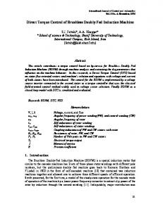
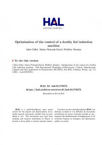
17th International Middle East Power Systems Conference, Mansoura University, Egypt, December 15-17, 2015 in the synchronous reference frame. The BDFIG is coupled to a variable speed wind turbine for wind energy generation systems. Vector control of the control winding is proposed to achieve high performance operation. The vector control system is designed based on the BDFIG synchronous reference farme (d-q) model. Two inner current control loops are designed to regulate the control winding current and an outer loop is designed to regulate the rotor speed. The performance of the proposed scheme is analyzed under different operating conditions such as sub-synchronous, supersynchronous and variable wind speed. Simulation works are carried out to evaluate the performance of the proposed scheme using Matlab /Simulink package. II. BDFIG MODELING The BDFIG has two three-phase windings in its stator, namely the power winding (PW) and control winding (CW), as shown in Fig. 1. To avoid direct coupling between the two windings, the pole pair numbers must be different by an integer [14]. Furthermore, in order to reduce asymmetryical electromagnetic forces on the rotor, that pole pair difference should be greater than one [15]. The stator PW of the BDFIG is connected directly to the grid and therefore operates at grid frequency producing an MMF in the air gap rotating at this frequency. Most of the power (7075%) will be transferred between the BDFIG and utility grid via this winding. The control winding is connected to the grid via a bidirectional partially rated frequency converter (25-30% of rated power) [7], [16]. The frequency converter consists of two back-to-back voltage source inverters. The inverter connected to the control winding, or the machine-side inverter (MSI), controls it's current and in turn affects the power winding current due to the indirect coupling between the two windings. The rotor is squirrel cage type, and hence, no brush or slip ring is required. The structure for the rotor winding is called the nested loop. Figure 2 shows the nested loop rotor stracture. As shown in the figute, the number of rotor nests or poles should be equal to the summation of stator windings pole pair numbers to provide indirect coupling between the powers and control winding magnetic fields [17]. The main operating mode of BDFIG is the synchronous mode, at which the power and control windings are cross-coupled through the rotor circuit. The shaft speed in this mode only depends on the supply frequencies of the two stator windings, i.e., it only depends on the variable output frequency from the converter if one stator winding is supplied from the mains [14]. The rotor shaft speed in rad/s is given by (1) where are the electric angular speed of the supplies to the power winding and control winding, respectively. The BDFIG is characterized by the so-called natural speed at which the stator control winding connected to the converter is
supplied by DC. For the machine 2/4 pole-pair BDFIG with the power winding connected to the 50 Hz grid, the natural speed is 500 r/min. A positive frequency, positive sequence voltage, is required for the control winding for the operation of BDFIG above the natural speed, while a negative frequency voltage feeding the control winding reduces the shaft speed below the natural speed. The BDFIG dynamical model described by the following equations in [18], [19] ( ) ( ) ( ) ( ( ) ) ( ) ( ( ) ) ( ) ( ) ( ) ( ) 50 HZ / Grid A B C
Frequency converter 50Hz XHz
Control winding(Pc)
BDFIG Power winding(Pp)
Fig.1. The structure of BDFIG
Fig.2 Nested loop rotor of BDFIG [19].
where the flux linkage expressed as:
( ) ( ) ( ) ( ) ( ) ( ) where are stator q -axis flux linkages components, are stator d-axis flux linkages components, are rotor q -axis and d -axis flux linkage component, are stator q -axis currentscomponents, are stator d -axis currents components, are rotor q -axis and d -axis current components, is power winding
17th International Middle East Power Systems Conference, Mansoura University, Egypt, December 15-17, 2015 leakage inductance, , is rotor leakage inductance, s is Laplace operator, are angular speeds of power and control winding respectively , is power winding resistance , is control winding resistance , is rotor resistance ,vdp, vdc , vqp, vqc and vdr , vqr are voltages of (power &control) windings and rotor windings correspondingly. are numbers of pole pairs of power and control windings, respectively. The electromagnetic torque can be expressed as: [ ] [ ] (14) The equation of drive movement is written as (15) where J is moment of inertia and B is friction coefficient and TL is load torque. A simplified equivalent circuit for the BDFM is shown in Fig. 3 [20], where all parameters are referred to the PW side and iron losses are neglected. The equivlant circuit is valid for all modes of operation, including the induction, cascade, and synchronous modes. In addition, the circuit can be utilized for the analysis of steady-state performance of the BDFM.
-( ) (16) where, θc-ref is reference value of the control winding voltage, θr is the rotor shaft position in rad measured by the shaft encoder and θp is the angle of power winding voltage in rad/s. the power winding voltage is estimatd using the PLL. -
‘‘ w r*
+ wr
PI
Id*
Iq* + -
PI
Vac
vq
Grid
Vbc
PWM
BDFIG
dq/ abc
Iq
Vcc +Id
PI
vd θp
Inverter
encoder θr wr
+PP+PC iCa
θr
Iq
abc/ dq0
Id θP PLL wp
Va Vb Vc
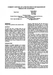
Fig. 4. Block diagram of the vector control scheme for the BDFIG.
IV. SIMULATION RESULTS Fig. 3. Equivalent circuit of the BDFIG.
III. VECTOR CONTROL OF BDFIG The proposed vector control scheme for the BDFIG is shown in Fig. 4. As shown in the figure, two current control loops are designed to regulate the control winding current (icd, icq). The reference and actual values of the control winding current are compared and the current error are fed to a current controller (PI-controller) to generate the control winding reference voltage values (Vcd, Vcq) which are converted from synchronous frame to d-q to stationary reference frame (abc) and then fed to the PWM technique to generate the switching signals of the machine side inverter. An outer control loop is designed to regulate the rotor speed and to generate the q-axis control winding current reference value where, the reference and actual speed are compare and fed to PI-controller. An encoder is required to provide rotor speed and position angle information for the dq transformation. The power winding voltage signals are measured and fed to a phase lock-loop (PLL) to estimate the angle and frequency of the power winding voltage. In the proposed vector control scheme, the reference angles determined based on the principle equation of the BDFIG operation in the synchronous mode. The relation between the control winding angle, power winding volatge angle and the rotor shaft speed in rad/s using (1) can be expressed as:
Simulation works are carried out using Matlab/Simulink package to analyze and evaluate the performance of the proposed vector control of BDFIG. The nominal parameters of the proposed machine are given in Table 1. The gains of the PI-controllers are selected to give optimum performance. For a speed controller, the PI-controller gains are selected to be Kp=1, Ki=10 and for id and iq current controllers, the PIcontrollers gains are selected to be Kp=5, Ki=50. The performance of the proposed scheme will be studied under different operating conditions, i.e., sub-synchronous rotor speed, super-synchronous rotor speed, variable wind speed and starting operation. Each operation case will be analyzed in the following sections. parameter
TABLE I: Parameters of the BDFIG.. value parameter 2.3Ω 4Ω 1.2967e-4 Ω 0.3498H B 0.3637 H J 2
value 4.4521e-5H 0.0031H 0.0022H 0.036N.m.s 0.53kg.m2 4
Case 1: Variable rotor speed operation. In this case, the studied when the synchronous rotor study the scheme
performance of the proposed scheme is DFIG is operated under sub- and superspeed while the wind speed is 10m/sec. To performance during transition, firstly, the
1.8
1.9
2 2.1 (a)T(s)
2.2
2.3
2.4
2.5
10 0
ids2,(A) iqs2(A
-10 -20 -30 1.5
1.6
1.7
1.8
1.9
2 2.1 (e)T(s)
2.2
2.3
2.4
2.5
400 200 0 -200 -400 1.9
1.95
2
2.05
2.1 (c)T(s)
2.15
2.2
2.25
2.3
1.7
1.8
1.9
2 2.1 (a)T(s)
2.2
2.5
10 0 ids2,(A) iqs2(A
-10 -20 -30 1.5
1.6
1.7
1.8
1.9
2 2.1 (e)T(s)
2.2
2.3
2.4
2.5
400 200 0 -200 -400 1.9
1.95
2
2.05
2.1 (c)T(s)
2.15
2.2
2.25
-50 1.5
1.6
1.7
1.8
1.9
2 2.1 (b)T(s))
2.2
2.3
2.4
1.8
1.9
2 2.1 (b)T(s))
-50 1.5
1.6
1.7
1.8
1.9
2 2.1 (d)T(s))
2 2.1 (d)T(s))
2.3
2.4
300 200 100
2.5
2.4
2.5
20 0 -20 1.9
0
0.5
1
1.95
2
2.05
2.1 (f)T(s)
2.15
2.2
2.25
2.3
100
0
-100
-200
1.5
0
0.5
1
1.5
time(s)
50
2.5
2.3
electromagnatic torque(N.m)
400
0
2.2
2.2
200
10 ia ib ic
0
1.9
2.5
.
ia ib ic
1.8
2.4
0
time(s)
1.7
2.3
ia ib ic
2.3
Nref(rpm) N(rpm)
50
1.6
2.2
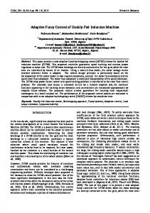
In this case, the performance of the proposed scheme is studied when the generator speed is increased from zero speed to 450 rpm. The generator speed, torque, control winding current (Iabc), reference and actual values of icd and icq are shown in Fig. 7. The oscillatory torque before reaching steady state speed is due to coupling between the harmonic fields produced by the rotor with noticeable amplitude and the power winding fluxes. Due to torque oscillations in the beginning of process, oscillations of speed also are seen. The frequency of the control winding decreases as the rotor speed increases. 500
-50
1.7
50
600
0
1.6
Case 2: starting operation
electromagnetic torque(N.m)
-50 1.5
2.4
Fig. 6. BDFM dynamic performance for a speed change from 550 rpm to 450 rpm. (a) Shaft speed. (b) Shaft torque. (c) power winding voltage. (d) control winding current. (e) iq&id .(f)power winding current .(g)Active & reactive power
50
1.5
2.3
Iabc control winding(v)
ids2,(A),ids2ref,iqs2(A),iqs2ref Vabc power winding(v)
1.6
Iabc power winding(A)
Nref(rpm),N(rpm)
450
electromagnatic torque(N.m) 0
electromagnatic torque(N.m)
1.7
Iabc control winding(v)
ids2,(A),ids2ref,iqs2(A),iqs2ref
1.6
500
50
0 ids2,(A),iqs2(A
450
Nref(rpm) N(rpm)
550
400 1.5
Nref(rpm),N(rpm)
500
600
Iabc control winding(v)
550
400 1.5
Vabc power winding(v)
Nref(rpm) N(rpm)
Iabc power winding(A)
Nref(rpm),N(rpm)
600
electromagnetic torque(N.m)
reference rotor speed is assumed to be 450 rpm (subsynchronous speed) and then increased to 550 rpm (supersynchronous speed). The results of the scheme are illustrated in Fig.5. The figure shows the reference and actual rotor speed, shaft torque, power and control windings currents, reference and actual values of control winding (icd, icq), respectively. It can be observed that the actual speed can track well the reference speed during steady state and transient operation. Also, the reference and actual values of the control winding currents are aligned. The scheme can transfer smoothly from sub-to super-synchronous region.The direct axis current component of control winding (icd) is constant during steady state and transient while the quadrature component icq is changed with reference speed and torque variation during transient period. The control winding three phase current waveforms show that its sequence is reversed when the machine is transferred from sub- to synchronous region. The power and control windings currents are nearly sinusoidal, balanced and free harmonics. Figure 6 shows the results of the proposed scheme when the rotor speed is changed from super- to sub-synchronous speed. The reference speed is assumed to be 550 rpm (supersynchronous speed) and then decreased to 450 rpm (subsynchronous speed). The figure shows the reference and actual rotor speed, shaft torque, power and control windings currents, reference and actual values of control winding (icd, icq), respectively. Compared to Fig. 5, the electromagnetic torque and the power winding current are increased during the transient period. The results illustrate the good performance of the scheme under constant wind speed and variable rotor speed. It is kown that the rotor speed of doubly fed insuction generators are changed to operate at maximum power point.
electromagnatic torque(N.m)
17th International Middle East Power Systems Conference, Mansoura University, Egypt, December 15-17, 2015
0
ids2,(A) iqs2(A
-10
-20
40 -50
20
0
0.5
1
1.5
-30
0
0.5
time(s)
0
1
1.5
time(s)
Fig. 7. Starting performance of BDFIG.
-20 -40 1.9
1.95
2
2.05
2.1 (f)T(s)
2.15
2.2
2.25
2.3
Fig. 5. BDFM dynamic performance for a speed change from 450 rpm to 550 rpm (a) Rotor speed. (b) Shaft torque. (c) Power Winding voltag. (d) Control winding current. . (e) iq&id .(f)Power winding current .(g)Active & reactive power
VI. CONCLUSION This paper represents a simplified Vector control scheme of the brushless doubly fed induction generators. Detailed theoretical model of the BDFIG with nested loop squirrel cage
17th International Middle East Power Systems Conference, Mansoura University, Egypt, December 15-17, 2015 is studied The controller consist of two loops for regulating the CW current ,the first loop was used to regulate the component and the second loop for . The rotor speed was controlled based on control. The machine model and the controller have been implemented in MATLAB /SIMULINK to simulate the BDFIG dynamic performance under different operating conditions. The modelling and performance BDFIG can be concluded as follows: 1- BDFIGs are simple construction, more reliable and less maintenance compared to the conventional DFIGs. 2- BDFIGs can operate well as a variable speed generator for wind energy applications. 3- The power winding current and in turn its active and reactive power can be controlled by controlling the control winding current without direct coupling between the two windings. 4- If the brushless doubly fed induction machine is operated as a motor or a generator at very low speed, an oscillations appear in the torque and current waveforms. REFERENCES [1] R. A. McMahon, X.Wang, E. Abdi-Jalebi, P. J. Tavner, P. C. Roberts, and M. Jagiela, “The BDFM as a generator in wind turbines,” in Proc. 12th Int. EPE-PEMC, 2006, pp. 1859–1865. [2] R. A. McMahon, P. C. Roberts, X. Wang, and P. J. Tavner, “Performance of BDFM as generator and motor,” Proc. Inst. Elect. Eng.—Electr. Power Appl., vol. 153, no. 2, pp. 289–299, Mar. 2006.. [3] P. J. Tavner, M. Jagiela, T. Chick, and E. Abdi-Jalebi, “A brushless doubly fed machine for use in an integrated motor/converter, considering the rotor flux,” in Proc. 3rd Int. Conf. PEMD, Mar. 2006, pp. 601–605. [4] M. Boger, A. Wallace, and R. Spée, “Investigation of appropriate pole number combinations for brushless doubly fed machines as applied to pump drives,” IEEE Trans. Ind. Appl., vol. 32, no. 1, pp. 189– 194,Jan./Feb. 1996. [5] R. A. McMahon, P. C. Roberts, X. Wang, and P. J. Tavner, “Performance of BDFM as generator and motor,” Proc. Inst. Elect. Eng.—Elect. Power Appl., vol. 153, no. 2, pp. 289–299, Mar. 2006. [6] D. Zhou, R. Spée, and G. C. Alexander, “Experimental evaluation of a rotor flux oriented control algorithm for brushless doubly-fed machines,” IEEE Trans. Power Electron., vol. 12, no. 1, pp. 72–77, Jan. 1997. [7] S. Shao, E. Abdi, F. Barati, and R. A. McMahon, “Stator-flux-oriented vector control for brushless doubly-fed induction generator,” IEEE Trans. Ind. Electron., vol. 56, no. 10, pp. 4220–4228, Oct. 2009. [8] J. Poza, E. Oyarbide, D. Roye, and M. Rodriguez, “Unified reference frame d-q model of the brushless doubly-fed machine,” Proc. Inst. Elect.Eng.—Elect. Power Appl., vol. 153, no. 5, pp. 726–734, Sep. 2006. [9] H. Gorginpour, H. Oraee, S.Member, “Calculation of Core and Stray Load Losses in Brushless Doubly Fed Induction Generators ,” IEEE Transactions on Industrial Electronics, VOL. 61, NO. 7, JULY 2014 [10] Sh. Shao, T. Long, E. Abdi, and R. A. McMahon “Dynamic Control of the Brushless Doubly Fed Induction Generator under Unbalanced Operation” IEEE transactions on Ind. Electronics, Vol.60, NO.6, JUNE 2013. [11] F. Barati, R.McMahon, Sh. Shao, E. Abdi, and H. Oraee ,“ Generalized Vector Control for Brushless Doubly Fed Machines With Nested-Loop Rotor” IEEE transactions on Iindusteral electronics ,Vol. 60, NO. 6, JUNE 2013. [12] Z. Tir and R. Abdessemed “Control of a wind energy conversion system based on brushless doubly fed induction generator,” Revue des Energies Renouvelables Vol. 17, No. 1, pp. 55 – 69, 2014. [13] T. Long, Sh. Shao, E. Abdi, R.A. McMahon, and Shi Liu, “Asymmetrical Low-Voltage Ride Through of Brushless Doubly Fed Induction Generators For the Wind Power Generation,” IEEE transactions on energy conversion,vol .28, NO.3, September 2013.
[14] R. A. McMahon, P. C. Roberts, X. Wang, and P. J. Tavner, “Performance of BDFM as generator and motor,” Proc. Inst. Elect. Eng.—Elect. Power Appl., vol. 153, no. 2, pp. 289–299, Mar. 2006 [15] S. Shao, E. Abdi, F. Barati, and R. A. McMahon, “Stator-fluxorientedvector control for brushless doubly-fed induction generator,” IEEE Trans. Ind. Electron., vol. 56, no. 10, pp. 4220–4228, Oct. 2009. [16] J. Poza, E. Oyarbide, I. Sarasola, and M. Rodriguez, “Vector control design and experimental evaluation for the brushless doubly fed machine,” IET Elect. Power Appl., vol. 3, no. 4, pp. 247–256, Jul. 2009. [17] A. R. W. Broadway and L. Burbridge, “Self-cascaded machine: A low speed motor or high-frequency brushless alternator,” Proc. Inst. Electr. Eng., vol. 117, no. 7, pp. 1278–1289, Jul. 1970.. [18] Y. Liu – X. Wang – Y. Xing, “An improved three level direct torque control method of brushless double-fed machine based on the fixed synthesizing vector” Engineering Review Vol. 33, Issue 3, 203-209, 2013. [19] Ayman Abdel-Khalik, Ahmed Elserougi, Ahmed Massoud and Shehab Ahmed "Brushless Doubly-Fed Induction Machine as a Variable Frequency Transformer" Journal of Energy and Power Engineering, Vol. 7, pp. 110-117, 2013.