Indonesian Journal of Electrical Engineering and Computer Science Vol. 6, No. 2, May 2017, pp. 387 ~ 395 DOI: 10.11591/ijeecs.v6.i2.pp387-395
387
Modelling and Simulation of Field Oriented Control based Permanent Magnet Synchronous Motor Drive System Faisal Amin*, Erwan Bin Sulaiman, Wahyu Mulyo Utomo, Hassan Ali Soomro, Mahyuzie Jenal, Rajesh Kumar Research Center for Applied Electromagnetics, Universiti Tun Hussein Onn Malaysia, Locked Bag 101, Batu Pahat, 86500, Malaysia *Corresponding author, e-mail:
[email protected]
Abstract On the basis of analysis of dq model of permanent magnet synchronous motor (PMSM) and principle of field oriented control (FOC), detail modelling of PMSM drive system and simulation results presented in this paper. The PMSM model is based on electronic components rather than mathematical blocks, this enabled us to achieve simulation results more realistic. Moreover all the modules of this simulation, such as inverter and pwm generator are made from scratch instead of using premade Simulink blocks. Simulation was carried on the basis of step change in speed and torque then made performance comparison of several parameters such as abc current, dq current, speed and torque. Keywords: FOC, PMSM simulation, dq model, synchronous motor, vector control Copyright © 2017 Institute of Advanced Engineering and Science. All rights reserved.
1. Introduction With the advancement of permanent magnetic materials, power electronics and computing technology, AC motors, specially PM synchronous motor were adopted by many industries because of its inherent qualities such as high torque to inertia ratio, good efficiency, low cost, high power density, easy maintenance [1, 2] and advance vector control which allows decoupled control of torque and speed of AC motor similarly to DC motor made synchronous motor more popular [3]. This paper analyses the dq equivalent circuit of PMSM [4], which is appropriate for implementing FOC, then modelling of PMSM based on the equivalent circuit and implementing FOC [5]. Realistic electronic components used for modelling PMSM for accuracy. Using powerful simulation capabilities of MATLAB/ Simulink, the entire drive system is modelled using modular approach. Whole simulation model is built around several independent functional modules such as dq model of PMSM, inverter, PWM generator, PI controller, Park and inverse Park transformation blocks. Final drive system is made through linking these separate modules in their appropriate orders [6]. By providing parameters of any specific motor, we get estimated performance characteristics graphs for that particular machine such as torque and speed.
2. Research Method Field oriented control was introduced during 70s. It is a control mechanism to flexibly drive synchronous and induction motor. It allows decoupling control of torque and speed of AC motors similar to separately excited DC motors. Since in DC motor, armature current which directly control the torque and field current in the rotor which produce magnetizing flux are independently accessible and armature mmf and rotor flux held orthogonally with respect to each other through mechanical commutation system such as brushes and commutators. But in case of AC motors (Synchronous and Induction motor), spatial angle between rotating stator field and rotor flux changes with the load which causes oscillatory response. FOC emulate the DC conditions in AC motor structure by monitoring the rotor field position and orient the stator field accordingly so that angle between
Received February 12, 2017; Revised April 25, 2017; Accepted May 9, 2017
IJEECS
ISSN: 2502-4752
388
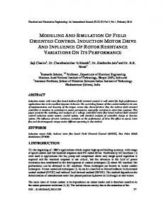
both of the fields can be maintain at 90o. In this way maximum torque condition can be achieved while independently controlling rotor speed [7–10]. FOC require a position sensor for constantly monitoring the rotor position, hence rotor flux position too. Stator field is oriented through varying phase and magnitude of three phase ac quantities. Hence it is also referred as ‘vector control’ [9-11] The flow chart describing the methodology of implementing FOC for PMSM is shown in Figure 1.
Start Design a converter block for calculating Iq from torque command
Design DQ mathematical model of PM Synchronous motor
Combining all these blocks to model Field Oriented Controller (FOC)
Using mathematical model, design DQ equivalent circuit of PMSM
Succesful modeling of FOC?
No Model PMSM in Simulink using DQ equivalent circuit
Yes Design PWM comparator based inverter model
Successful modeling of PMSM?
Yes
No
Design motor Torque and torque to speed calculation blocks
Design park and inverse park transformation blocks
Design a PI controller block for keeping Id to 0 Amp for max Torque operation
Combine PMSM, FOC and Inverter models to simulate a complete FOC based PMSM drive
Optimize performance through varying the parameters of motors and PI controllers No
Required torque and speed characteristics graphs achieved from the simulation?
Design 2nd PI block for estimating required torque from reference speed
Yes End
Figure 1. Flow chart of implementing FOC for PMSM
Modelling and Simulation of Field Oriented Control based PMSM Drive System (Faisal Amin)
389
ISSN: 2502-4752
2.1. Mathematical Model of PMSM Mathematical model of PMSM describe in this paper is based on following assumptions 1. Core saturation and winding leakage inductance are ignored 2. Sine distribution of magnetic potential in the air gap 3. Higher harmonic waves in the magnetic field are negligible Within these assumptions and using dq coordinate transformation, the mathematical model of PMSM in dq rotating coordinate system is represented in terms of following equations [12, 13]. DQ transformed voltages are given by: Vq = Rsiq +ωrλd + ρλq
(1)
Vd = Rsid −ωrλq + ρλd
(2)
Flux Linkages are given by: λq = LqIq
(3)
λd = LdId + λf
(4)
Substituting Equations 3 and 4 into 1 and 2. Vq = Rsiq + ωr(Ldid + λf) + ρLqiq
(5)
Vd = Rsid - ωrLqiq + ρ(Ldid+λf)
(6)
Arranging Equations 5 and 6 in matrix form: ρ
ω
ω
ρ
ωλ ρλ
(7)
The developed torque motor is being given by: λ
λ
(8)
The mechanical Torque equation is: ω
ω
(9)
Solving for the rotor mechanical speed form Equation 3.9 ω
ω
(10)
and ω
ω
Where ωr is the rotor electrical speed where asωm is the rotor mechanical speed.
2.2. Equivalent Circuit of PMSM Following equivalent circuit of PMSM is based on Equation 5 and 6.
IJEECS Vol. 6, No. 2, May 2017 : 387 – 395
(11)
IJEECS
ISSN: 2502-4752
390
Figure 2. DQ equivalent circuit of PMSM
2.3. Simulation of FOC Drive System of PMSM Simulation of FOC drive system of PMSM is based on the mathematical model and the motor equations. It is built on several blocks such as DQ model of PMSM, Park and Inverse Park transformation block, torque and speed block, PI control, PWM generator and inverter [14, 15]. PMSM block consist of d and q axis circuits as shown in Figure 3 and 4. These blocks are made using equivalent circuit of Figure 2.
Figure 3. PMSM model (Top level)
(a)
(b) Figure 4. (a) q-axis circuit (b) d-axis circuit
Torque calculation block are based on equation 8 as shown in Figure 5(a) and speed calculation is based on Equation 10 and 11. It is shown in Figure 5(b).
Modelling and Simulation of Field Oriented Control based PMSM Drive System (Faisal Amin)
391
ISSN: 2502-4752
(a)
(b)
Figure 5. (a) Torque calculation block (b) Speed calculation block
Park and inverse park transformation blocks are used for conversion of parameters in different phase domains. They are also referred as abc-dq and dq-abc transformation as illustrated in Figure 6(a) and 6(b).
(a)
(b)
Figure 6. (a) abc-dq conversionblock (b) dq-abc conversion block
PWM generation block as shown in Figure 7(a), is used to compare calculated phase current Iabc (ref) with the current reading from motor Iabc and generate pwm signals, which is fed to the inverter. Inverter model is shown in Figure 7(b). For each phase, one switch is used to set negative and positive DC level. PWM signals from PWM generation block controls the inverter’s phase voltage.
(a)
(b)
Figure 7. (a) PWM generation block (b) Inverter block
IJEECS Vol. 6, No. 2, May 2017 : 387 – 395
IJEECS
ISSN: 2502-4752
392
Using all the modules, the complete FOC drive system for PMSM has been developed as shown in Figure 8.
Figure 8. Complete FOC model of PMSM
3. Results and Analysis After completion of modelling FOC drive system, it has been simulated and tested in two different control modes, variable speed and torque, through step change in the commanded parameters. These results were obtained by using the motor parameters as listed in Table 1. These parameters were taken from [11].
Table 1. Pmsm Parameters Used For Simulation Parameters rated voltage output power rated stator current pole pairs rated speed stator resistance PM flux linkage q-axis inductance d-axis inductance Motor Inertia
Symbol VLL POUT Is P ωm Rs λaf Ld Lq J
Value 220 V 900 W 16.7 A 4 1700 rpm 4.3 Ω 0.272 Wb-turns 27 mH 67 Mh 0.000179 kg m2
3.1. Variable Speed Mode In variable speed mode, two different speed commands are given through a step block. Initially speed was set to 200 rpm for 30 msec, then it was increased to 500 rpm. But load torque is kept at a constant value of 3 Nm throughout the simulation. Following are the graphs obtained from the variable speed mode. 3.1.1. Iabc Current Response Figure 9 illustrate Iabc current response in variable speed mode, it was obtained from reverse park transformation. Initially waveforms are distorting but during steady state of initial
Modelling and Simulation of Field Oriented Control based PMSM Drive System (Faisal Amin)
393
ISSN: 2502-4752
commanded speed of 200 rpm, the response is close to sinusoidal waveforms. After 30 msec, when commanded speed increases to 500 rpm, distortion occurs again due to the non gradual increase in the input command. But steady state achieved after 10 msec. It is also observed that waveform frequency increases during 500 rpm. Although amplitude is having same for both speed. 3.1.2. Idq Current Response The dq component of current is shown in Figure 10, its d component is almost remain at zero as commanded throughout the graph. But some distortion can be seen in the non stable regions due to sudden changes in speed.
Figure 9. abc current in variable speed mode
Figure 10. Idq current in variable speed mode
3.1.3. Speed Response Figure 11 shows the electrical versus mechanical speed response graph. The difference between these two terms is due to number of poles as explained in Equation 11. It is also observe that a time is required for the motor to gradually reach at the desired speed. According to the graph, it is about 10 msec. In both of the steady states, the response is almost linear and very close to the commanded values. 3.1.4. Generated Torque Response Figure 12 shows that in spite of constant torque operation, there can be seen large spikes of torque during non-steady state modes, during these periods speed is gradually increased and high torque needed until stability gained. Apart from these large spikes, torque is kept constant at input load value of 3 Nm in steady states.
Figure 11. Electrical verses mechanical speed in variable speed mode
IJEECS Vol. 6, No. 2, May 2017 : 387 – 395
Figure 12. Developed torque in variable speed mode
IJEECS
ISSN: 2502-4752
394
3.2. Variable Torque Mode In variable torque mode, two different load values are input through step block. Initial load value is set to 1 Nm and final value is set to 3 Nm. While speed is kept constant throughout this simulation mode Following are the graphs obtained from the variable torque mode. 3.2.1. Iabc Current Response Figure 13 illustrate Iabc current response in variable torque mode. Waveform is non sinusoidal in the beginning. After gaining stability, sinusoidal waveform achieved It has also been observed that waveform amplitude is decreased during less load value. Variation of amplitude indicates that for more torque more current is needed. Frequency is constant for both of the load values. It is due to constant speed operation. 3.2.2. Idq Current Response Figure 14 illustrates dq current response during variable torque mode. Likewise in variable speed mode, its d component is almost zero. Few distortions in both d and q components can be seen before steady state. While sudden change in load does not impact dq components severely as we have seen during variable speed mode.
Figure 13. abc current in variable torque mode
Figure 14. Idq current in variable torque mode
3.2.3. Speed Response Figure 15 shows the electrical versus mechanical speed response graph. After gradually increases the speed upto commanded value, response is quite linear and sudden change in load does not impact the speed response. 3.2.4. Generated Torque Response Figure 16 shows that the torque response in variable torque mode is quite good as compare to that of variable speed mode. Although few distortion can be seen before steady state.
Figure 15. Electrical verses mechanical speed in variable torque mode
Figure 16. Developed torque in variable torque mode
Modelling and Simulation of Field Oriented Control based PMSM Drive System (Faisal Amin)
395
ISSN: 2502-4752
4. Conclusion Achieved results shows that the simulation model has good dynamic response in terms of torque and speed. Although by comparing the results from both simulation modes, it has been observed that simulation perform better in variable load mode because if we observe the graphs of torque and current in variable speed mode, large overshoots can be seen in nonsteady state, whenever there is sudden change in commanded speed. Since we use step command for varying torque and speed both. But non gradual increase in torque does not affect the system stability that much. For instance, speed does not affect at all by sudden load variation as shown in Figure 15. Even current values are not overshooting, although slight oscillation in dq current graph can be seen before steady state region as shown in Figure 14. But overall system performance is quite stable and able to meet certain requirements. In most applications, speed kept constant while load may vary with the passage of time and simulation results shows this system is quite insensitive to load torque, no overshoots has been observed while varying the load and speed remain perfectly constant as commanded.
References [1]
[2] [3] [4] [5] [6]
[7] [8] [9] [10]
[11]
[12] [13] [14] [15]
Zhang Z and Shu J. Matlab-based permanent magnet synchronous motor vector control simulation.In Computer Science and Information Technology (ICCSIT) 3rd IEEE International Conference. 2010; 9: 539-542. Junfeng C. Permanent Magnet Motor. China Machine Press. Beijing. 2002. Bose BK. Modern power electronics and AC drives: Prentice Hall. 2002. Dehkordi AB, Gole AM and Maguire TL. Permanent magnet synchronous machine model for realtime simulation. In International Conference on Power Systems Transients (IPST’05) 2005; 5:19-23. Ohm DY. Dynamic model of PM synchronous motors. Drivetech Inc., Blacksburg, Virginia, www. drivetechinc.com, 2000. Liu T, Tan Y, Wu G, and Wang S. Simulation of PMSM vector control system based on Matlab/Simulink. International Conference on Measuring Technology and Mechatronics Automation. 2009; 2: 343-346. Cheng Q, Yuan L. Vector Control of an Induction Motor based on a DSP. M. Sc. Thesis. Chalmers University of Technology, Goteborg, Sweden. 2011. Blaschke F. A new method for the structural decoupling of AC induction machine. IFAC Conference Record, Dusseldorf, Germany. 1971: 1-5. Sathiakumar S, Biswas SK, Vithyathil J. Microprocessor based field oriented control of a CSI fed induction motor drive. IEEE Trans. Ind. Electron. 1986; 33: 39-43. Tomer AS and Dubey SP. Response Based Comparative Analysis of Two Inverter Fed Six Phase PMSM Drive by Using PI and Fuzzy Logic Controller. International Journal of Electrical and Computer Engineering 2016; 6(6): 2643. Alamri YA, Idris NR, Alsofyani IM andSutikno T.Improved Stator Flux Estimation for Direct Torque Control of Induction Motor Drives. International Journal of Power Electronics and Drive Systems 7. 2016; 4. Kumar TP and Samyuktha P. Vector Control Drive of Permanent Magnet Synchronous Motor Using Resolver Sensor. International Journal of Computer Science Engineering (IJCSE). 2013; 2(04). Muñoz DV. Design, Simulation and Implementation of a PMSM Drive System. M. Sc. Thesis, Chalmers University of Technology, Göteborg, Sweden. 2011. Merzoug MS, Benalla H. Nonlinear Backstepping Control of Permanent Magnet Synchronous Motor (PMSM). International Journal of Systems Control. 2010; 1. Merzoug MS, Naceri F. Comparison of Field-Oriented Control and Direct Torque Control for Permanent Magnet Synchronous Motor (PMSM). in Proc. World Academy of Science, Engineering and Technology. 2008; 35: 299-304.
IJEECS Vol. 6, No. 2, May 2017 : 387 – 395