Modelling and Specifying Scenarios and Agent Behaviour∗ Lijun Shan Department of Computer Science National University of Defence Technology Changsha, China Email:
[email protected] Abstract Based on our previous work on the formal specification language SLABS as well as a methodology and modelling language for modelling and specifying multi-agent systems, we further investigate how diagrammatic models of multi-agent systems can be used to derive formal specifications in SLABS. The modelling language is further developed by introducing behaviour diagrams and scenario diagrams for modelling agents’ behaviour in various scenarios of their environment. It supports derivation of the specifications of agents’ behaviour through scenario analysis. The language and its usage are illustrated by an example of the evolutionary multi-agent ecosystem Amalthaea developed at MIT Media Lab.
1. Introduction The necessity of a rigorous and formal methodology for developing multi-agent systems has been widely recognized due to the difficulties in analysis, specification, design, implementation and testing autonomous and intelligent behaviours of such systems; c.f. [1, 2]. Much work has been done in the area of formal modelling of agents’ rational behaviour by logic systems and game theories; c.f. [3~7]. On the other hand, research has also been reported in the literature about the development processes and methods for engineering agent-based systems by utilizing diagrammatic notations, e.g. [8~12]. Unfortunately, there is a big gap between these two approaches. In this paper, we investigate how models of multiagent systems described in a diagrammatic notation can be used to derive formal specifications. In our previous work [13~15], a language called SLABS has been designed for the formal specification of agent-based systems. In [16] a diagrammatic notation and a methodology for modelling multi-agent system’s ∗
Hong Zhu Department of Computing Oxford Brookes University Oxford OX33 1HX, England Email:
[email protected] architecture were proposed so that the formal specifications in SLABS can be derived from semi-formal models of multi-agent systems. The analysis of agents’ behaviour is one of the key tasks in our methodology. Based on our previous work, this paper further develops the diagrammatic modelling language to support scenario analysis and derivation of behaviour rules for formal specifications of agents. This paper is organized as follows. Section 2 briefly reviews the formal specification language SLABS and the underlying model of agent-based systems. Section 3 presents a diagrammatic notation for modelling agentbased systems. The notation consists of the collaboration diagrams introduced in [16] and the behaviour diagrams and scenario diagrams proposed in this paper. Section 4 is a case study of a non-trivial evolutionary multi-agent system Amalthaea. Section 5 summarizes the results of the paper and discusses further research directions.
2. The language SLABS and its meta-model In [13], we proposed the language SLABS, which stands for Specification Language for Agent-Based Systems. It was further developed in [14] by defining its formal semantics and in [15, 16] by investigating its pragmatic issues and case studies. The language is based on a meta-model of multi-agent systems, which can be characterized by a set of pseudo-equations [14]. In particular, pseudo-equation (1) below states that agents are defined as real time active computational entities that encapsulate data, operations and behaviour rules and they situate in their designated environments. Here, data represent an agent’s state. Operations are the actions that an agent can take. Behaviour rules determines how an agent changes its state and takes actions in the context of its environment. By encapsulation, we mean that an agent’s state can only be changed by the agent itself, and each agent has its own rules that govern its behaviour to
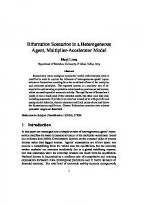
Work reported in this paper is partly supported by China National High Technology Research Programme (863 Programme) under grant 2002AA116070.
decide ‘when to go’ and ‘whether to say no’. Agent = Environment (1) As an extension to the notion of class in objectorientation, a caste is a set of agents that have the same structural and behavioural characteristics as stated in pseudo-equation (2). An agent is an instance of a caste. It can also join in and retreat from a caste at run-time. Therefore, which agents are in a caste depends on time, hence the subscript t in pseudo-question (2). A caste can inherit from a number of other castes. As argued in [15], castes play a significant role in the construction of multiagent systems. Fig. 1 shows the structure of caste description in SLABS. Castes t = {agent | structure characteristics & behaviour characteristics} (2)
In a behaviour rule, the pattern on the left-hand-side of the → symbol describes the pattern of the agent’s previous behaviour. The scenario describes the situation in the environment, comprising behaviour histories of the agents in the environment. The where-clause is the precondition of the action. The event of the right-hand-side of → symbol is the action to be taken when the scenario happens and the pre-condition is satisfied. An agent may have a non-deterministic behaviour. The expression prob in a behaviour rule is an expression that defines the probability for the agent to take the specified action on the scenario. If the probability expression is omitted, it means that the probability is not 0. Table 1 and 2 give the formats and the meanings of patterns and scenarios, respectively. Table 1 Meanings of patterns Pattern $ Action variable P^k
Fig. 1 Structure of caste description in SLABS Equation (3) states that a multi-agent system consists of a set of agents. Notice that, our definition of agent implies that object is a special case of agent in the sense that it has a specific rule of behaviour. Therefore, everything in a multi-agent system is an agent. The environment of an agent is a subset of the agents in the system, where some agents in the system may not be visible from the agent’s point of view. The environment description of an agent or a caste defines which agents in the system are visible. Hence, we have pseudo-equation (4) below. MAS = {agent n}n∈Integer (3) Environment t (Agent, MAS) ⊆ MAS – {Agent} (4) The SLABS language and the underlying meta-model of MAS do not define any specific communication language or protocol. The mechanism of communication is that an agent’s actions and states are divided into two parts: the visible ones and invisible ones. Agents communicate with each other by taking visible actions and changing visible state variables, and by observing other agent’s visible actions and state variables. This is expressed in pseudo-equation (5). Communication from agent A to agent B = A. Action + B. Observation (5) In SLABS, an agent’s behaviour is defined by a set of rules that describe its responses to environment scenarios. A behaviour rule has the following structure. Behaviour-rule ::= [] pattern | [prob] → event, [if Scenario][where pre-cond]; (6)
! Predicate Act (a1, a2, …ak) [p1, … pn]
Meaning The silence event It matches an action A sequence of k events that match pattern P The state of the agent satisfies the predicate An action Act that takes place with parameters match (a1, a2, …ak) The previous sequence of events match the pattern p1, … pn
Table 2 Semantics of scenario descriptions Scenario A: P ∀X∈C: P ∃[m]X∈C: P
µX∈C: P S1&S2 S1∨S2 ¬S
Meaning The situation when agent A’s behaviour matches pattern P The situation when the behaviour of all agents in caste C match pattern P The situation when there exists at least m agents in caste C whose behaviour matches pattern P where the default value of the optional expression m is 1 The number of agents in caste C whose behaviour matches pattern P The situation when both scenario S1 and scenario S2 are true The situation when either scenario S1 or scenario S2 or both are true The situation when scenario S is not true
For example, the following is the behaviour rule of a search engine. It states that if there is an agent A in the environment that takes the action of calling the search engine with a set of keywords, it will return a set of urls that matches the keywords.
[$] |→ SearchResult (keywords, urls); if ∃A: [Search (keywords)]
3. The modelling language We model an agent-based system at two levels. On macro-level, the relationships between the agents are described. On micro-level, the behaviour of each agent is described. The methodology can be summarized as a process that consists of the following activities. (1) Architectural analysis identifies agents in the system, groups the agents into castes, analyses inheritance and aggregation relationships between the castes, and documents them into a caste diagram. (2) Interaction analysis identifies the agents’ visible actions and states as well as the interactions between the agents, and documents them into collaboration diagrams. (3) Scenario analysis identifies the typical scenarios that each agent will deal with and its designed behaviour in the scenarios. This results in a set of behaviour rules. (4) When an agent’s behaviour is too complicated to be analysed by scenario analysis, decomposition and refinement are applied to the agent/caste by iterating the steps of interaction analysis and architectural analysis. (5) Derivation of formal specification produces a formal specification of the multi-agent system in SLABS from the models represented in the form of diagrams. In [16], we addressed the structural issues in the modelling of multi-agent systems and devised a diagrammatical notation. The notation of collaboration diagrams consists of two types of nodes: agent nodes and caste nodes. An agent node represents a specific agent in the system. A caste node represents all agents in the caste. Arrows between nodes represent communications between the agents. The collaboration diagram in Fig. 2 represents the Ecosystem of the evolutionary multi-agent system Almalthea [17].
In this paper, we propose a notation for modelling at the micro-level, i.e. the behaviour of individual agents. A behaviour model is represented by behaviour diagrams, which may include or refer to some scenario diagrams. For each agent, a behaviour diagram visually represents the agent’s behaviour rules, while scenario diagrams represents the agent’s view of the state of the multi-agent system.
3.1 Scenario diagram A scenario is a description of an agent’s view of the state of a multi-agent system. It plays an important role in our methodology. A scenario is composed of behaviour patterns of a set of agents in the environment. The behaviour patterns are combined together through logic connectives. Accordingly, a scenario diagram as a facility to describe a scenario is horizontally divided into three parts: the scenario’s identifier, behaviour descriptions and a logical connection network, as shown in Fig. 3. The behaviour descriptions are vertically divided into several parts called the swim lanes. Each swim lane contains a quantifier, which describes ‘who is swimming’ by giving the name of the agent or a quantifier applied to a caste, and a sequence of events of the swimmer in temporal order. Temporal relations between events of different swimmers are indicated using arrows across the swimming lanes, when synchronization is important; otherwise, swimmers are assumed to execute in parallel and their events are concurrent.
Fig. 3 Structure of scenario diagrams
Fig. 2 Example of collaboration diagram
There are two types of event nodes: action nodes and predicate nodes. An action node represents a visible action of the swimmer. A predicate node represents that the value of a visible state of the swimmer satisfies the certain condition given in the node. These nodes are linked by two types of arrows for their temporal order, as shown in Fig. 4. A solid line arrow from node A to node B indicates that the swimmer takes the action of B or is in the state that satisfies the predicate in node B immediately after action or state of A. A dashed line arrow from node A to B means that the swimmer takes the action or in the state of B after action/state A, while the swimmer may engage in other actions and/or in other states in the time
gap between A and B. Fig. 4 gives the notation of scenario diagrams. t: Act(p1,…pn)
Action node: the agent takes an action Act(p1,…pn) at time t, where p1,…pn are parameters of the action.
R-Exp Repetitive
t: Act(p1,…pn)
t:
State node: the agent’s state satisfies the predicate at time t.
Predicate
C-Exp
t:
Predicate
&
or
A T-Exp
B A T-Exp
B
action node: the agent takes an action repetitively at time t, where R-Exp defines the number of repetition of the action.
ר
Continuous state node: the agent’s state satisfies the predicate for a continuous period of time at time t, where the period satisfies the C-Exp. Logical connective nodes of AND, OR, and NOT, respectively: to combine behaviour patterns or scenarios.
a box with dashed line border and a precondition inside. A scenario node is represented as a round-corner rectangle, which may contain either simply a scenario name referring to a special scenario diagram, or a detailed scenario description. Several scenarios can be logically linked to form combined scenarios using logic connective nodes. Scenario Precondition
Scenario node: contain a scenario name or a detailed scenario description. Precondition node: give the precondition of an event. Action arrow: a link from behaviour rule’s previous events to the event to be taken. Logical arrow: a link from scenario node to action arrow.
Fig. 5 Additional notations of behaviour diagrams Behaviour rules in one behaviour diagram can be depicted independently or jointly. For example, the following diagram in Fig. 6 represents two related behaviour rules of one agent.
Temporal order arrow: event B is immediately after event A. -Exp is the time constraints on the time interval between the events. Discrete temporal order arrow: event B is after event A, while there may be other events between them. T-Exp is the time constraints on the time interval between the events.
Fig. 4 Notation of scenario diagrams Scenarios can be defined within a behaviour diagram where it is used. However, when a scenario is either too complex to be depicted in a behaviour diagram or repeatedly used in several behaviour rules, it can be defined in a scenario diagram and assigned a name. Thus, the scenario as a whole can be treated as a reusable module and referred to in certain behaviour diagrams.
3.2 Behaviour diagram The notation of behaviour diagrams includes the notation of scenario diagrams plus two types of arrows and three types of nodes, as shown in Fig. 5. In a behaviour diagram, the event to be taken is linked to previous events through an action arrow. Each action arrow can be associated with a scenario node and a precondition node. A precondition node is represented as
Fig. 6 Two behaviour rules jointly described in one behaviour diagram The elements in behaviour model defined above correspond to the contents in formal behaviour rule defined by (6). Therefore, the equivalent formal specifications in SLABS can be easily derived from diagrammatic models in the following way. With nodes and links in a scenario diagram transformed into equivalent formal expressions in SLABS, a swimming lane containing a sequence of event nodes linked by temporal arrows can be transformed into a pattern in scenario, and in turn a well-formed scenario diagram into a formal scenario description. Concerning a behaviour diagram, the sequence of event nodes before and after the action arrow can respectively be transformed into the pattern and event part of a formal behaviour rule, and the scenario nodes and precondition node respectively into the formal scenario and precondition expression. Consequently, for each agent in a multi-agent system, the
formal specification with behaviour rules as the core part can be derived from the system’s diagrammatic model that comprises the behaviour model proposed in this paper. Automation of the derivation is within our future work.
Confidence→N for information discovery agents. Then, the behaviour of the Ecosystem in the scenario when receiving a rating on a digest can be described as Fig. 7.
4. Case study In this section, we illustrate the usage of the modelling language by an example. We will analyse the Amalthaea system, which is an evolutionary multi-agent ecosystem developed at MIT Media Laboratory [17] aiming to assist its users in finding interesting information on the web. There are two species of agents in the system: filtering agents that model and monitor the interests of the user and discovery agents that model the information sources. These agents evolve, compete and collaborate in a market-like ecosystem. Agents that are useful to the user or other agents reproduce while low-performing agents are destroyed. The evolution of the system enables it to keep track of the changing interests of the user. In [16], we have discussed how to develop its formal specification in SLABS following our proposed process. Amalthaea is composed of the User Interface, the Ecosystem, the WWW search engines, WKV (Weighted Keyword Vector) Generator and Database of the retrieved document. The Ecosystem, containing two types of agent: the information filtering agents and the information discovery agents, has complicated behaviour. Here we graphically describe its behaviour rules through behaviour and scenario analysis. The agents that constitute the Ecosystem operate under a penalty/reward scheme supported by the notion of credit. Each agent has fitness level expressed in the form of the accumulated amount of credit that it has received according to its performance. And each agent has to pay “rent” following a linear decay credit function. Credit, thus, serves as the fitness function of the agents. The higher the fitness of an agent, the more chances it gets to survive and produce offspring. In analysis of the Ecosystem’s behaviour, the following scenarios are identified. • Scenario 1: when the user’s rating on a presented digest is passed to the Ecosystem through the interface. • Scenario 2: when it is the time for the agents to pay. In scenario 1, when credit is assigned by the user through feedback on the relevance of an item in the digest, the system relates this feedback to the filtering agents that proposed the item and discovery agent that retrieved it and assigns the credit to the agents. We assume the function CreditIFA: Rate × Confidence→N calculates the amount of the credit to be given to the information filtering agent and CreditIDA: Rate ×
Fig. 7 Behaviour diagram for Ecosystem’s behaviour in scenario 1 From this diagram the following rule can be derived. Rule 1: [$] |→(Credit(A, c1), Credit(B, c2)); If Interface: [PassRating (url, r)] & ∃A∈IFA: [$, Submit(url,confidence), $^k] & ∃B∈IDA: [Available(url, wkv), $^k’], where c1=CreditIFA(r, confidence) & c2=CreditIDA(r, confidence) The evolution of the Ecosystem is triggered by scenario 2. After all agents have paid their rents, decisions are made on who will be purged and who will produce offspring. It depends on two factors: the fitness of individual agent and the fitness of the whole system. The overall fitness is measured according to the percentage of positive feedbacks from the user in the past N ratings. Only a variable number of the best performing agents in the whole population are allowed to produce offspring, while a number of worst performing agents are to be purged. Assume that the function NumberofPurges (N_rating) and NumberofOffspring(N_rating) respectively calculates the number of agents to be purged and that to be generated from the most recent N ratings. The behaviour rules of “purge” and “generate” share the same scenario of “RentPaid”, which is represented in the scenario diagram in Fig. 8. The rules of purge and generate are described in Fig. 9 and Fig. 10, respectively. ∀X: IFA
RentPaid ∀Y: IDA
Interface
Pay(c1)
Pay(c2)
PassRating(rn)
N
&
Fig. 8 Scenario diagram for the situation when all agents have paid their rents
5. Conclusion
Fig. 9 Ecosystem’s behaviour rule for purge agents
Fig. 10 Ecosystem’s behaviour rule for generating new agents The formal definitions of these rules of Ecosystem can be derived from the above behaviour diagrams and the scenario diagram. Rule 2: [!(A∈IFA∪IDA)] |→ Purge(A)!(A∉IFA∪IDA); If ∀ X: IFA:[Pay(c)] & ∀Y:IDA:[Pay(c)] & Interface:[PassRating(rn)^N]; where A∈PurgeSet & PurgeSet ⊆{X | X∈IFA or X∈IDA} & ∀X∈PurgeSet.∀Y∉PurgeSet.(X.fitness≤Y.fitness) & ||PurgeSet||=NumberofPurges (n=1,…,N) Rule 3: [!(A∉IFA∪IDA)]|→ Generate(A)!(A∈IFA∪IDA); If ∀ X :IFA:[Pay(c)]& ∀Y:IDA:[Pay(c)] & Interface:[PassRating(rn)^N]; where A∈ NewAgentSet ∪ NewAgentSetSpec Therefore, we have the following specification of the Ecosystem in SLABS.
In this paper, we further developed the diagrammatic agent-oriented modelling language to support the modelling and specification of multi-agent systems. We addressed the micro-level modelling issues, which include the analysis of system scenarios and the descriptions of agents’ behaviour, and the derivation of behaviour rules in formal specifications. The uses of the language are illustrated by an example of an evolutionary multi-agent ecosystem Amalthaea. We are currently developing a software tool to support the construction of agent-based system models. The tool is designed to support automatic or semi-automatic generation of formal specifications in SLABS from graphic models. There are a number of important issues to be addressed in the future. First, consistency constraints between the diagrams must be explicitly specified and algorithms for automatically checking the constraints must be developed. Second, transformation rules from diagrams and dictionaries to formal notations must be specified and algorithms for automatic implementation of the rules must be developed.
Acknowledgement The authors are most grateful to Prof. Zhichang Qi, Dr. Xinjun Mao and Mr. Qi Yan at National University of Defence Technololy, China for their comments on earlier drafts of the paper and the discussions on related subjects.
References [1] Rash, J. L. et al (eds.), Formal Approaches to Agent-Based Systems, First International Workshop, FAABS2000, Springer Lecture Notes in Computer Science, Vol. 1871, 2001. [2] Meyer, J-J., Schobbens, P-Y. (eds.), Formal Models of Agents-ESPRIT Project ModelAge Final Workshop Selected Papers. LNAI, Vol. 1760. Springer (1999) [3] Rao, A.S., Georgreff, M.P., “Modeling Rational Agents within a BDI-Architecture”. In Proc. of the International Conference on Principles of Knowledge Representation and Reasoning (1991) 473-484. [4] Singh, M.P., “Semantical Considerations on Some Primitives for Agent Specification”. In: Wooldridge, M., Muller, J., Tambe, M. (eds.) Intelligent Agents. LNAI, Vol 1037. Springer (1996) 49-64 [5] Wooldridge, M., Reasoning About Rational Agents. The MIT Press (2000) [6] Ambroszkiewicz, S., Komar, J., “A Model of BDI-Agent in
Game-Theoretic Framework”. In: [2] (1999) 8-19 [7] Wooldridge, M. and Jennings, N.R., “Agent Theories, Architectures, and Languages: A Survey”. In: Intelligent Agents. LNAI, Vol. 890. Springer-Verlag (1994) 1-32 [8] Kinny, D., Georgeff, M., Rao, A., “A Methodology and Modelling Technology for Systems of BDI Agents”, In: Agents Breaking Away, Proc. of MAAMAW’96. LNAI, Vol. 1038. Springer-Verlag (1996) [9] Moulin, B., Brassard, M., “A Scenario-Based Design Method and An Environment for the Development of MultiAgent Systems”. In: Lukose, D. and Zhang, C. (eds.): First Australian Workshop on Distributed Artificial Intelligence. LNAI, Vol. 1087. Springer-Verlag (1996) 216-232
[12] Bauer, B., Muller, J.P. and Odell, J., “Agent UML: A Formalism for Specifying Multiagent Software Systems”. In: Ciancarini, P. and Wooldridge, M. (eds.): Agent-Oriented Software Engineering. LNCS, Vol. 1957. Springer (2001) 91103 [13] Zhu, H., “Formal Specification of Agent Behaviour through Environment Scenarios”. In: [1]263-277. [14] Zhu, H., “SLABS: A Formal Specification Language for Agent-Based Systems”. Int. J. of Software Engineering and Knowledge Engineering 11(5) (2001) 529-558 [15] Zhu, H., “The Role of Caste in Formal Specification of MAS”. In: Proc. of PRIMA’2001. LNCS, 2132. Springer (2001) 1-15
[10] Wooldridge, M., Jennings, N., Kinny, D., “A Methodology for Agent-Oriented Analysis and Design”. In: Proc. of ACM Third International Conference on Autonomous Agents, Seattle, WA, USA (1999) 69-76
[16] Zhu, H., “Formal Specification of Evolutionary Software Agents”, in Formal Methods and Software Engineering, Proc. of ICFEM’2002, George, C. and Miao, H., (eds), Springer LNCS 2495, (2002) 249-261.
[11] Iglesias, C.A., Garijo, M., Gonzalez, J.C., “A Survey of Agent-Oriented Methodologies”. In: Muller, J.P., Singh, M.P., Rao, A., (eds.) Intelligent Agents V. LNAI, Vol. 1555. Springer, Berlin (1999) 317-330
[17] Moukas, A., “Amalthaea: Information Discovery and Filtering Using a Multi-Agent Evolving Ecosystem”. Journal of Applied Artificial Intelligence, 11(5) (1997) 437-457.