in order to optimize the design of probe-coils and study various configurations ... the current-carrying coil and the material under test; the presence of defects or ...
PIERS ONLINE, VOL. 6, NO. 3, 2010
237
Modelling and Validating Ferrite-core Probes for GMR-eddy Current Testing in Metallic Plates M. Cacciola, G. Megali, D. Pellican` o, S. Calcagno, M. Versaci, and F. C. Morabito DIMET Department, University “Mediterranea” of Reggio Calabria Via Graziella Feo di Vito, I-89100 Reggio Calabria, Italy
Abstract— Non Destructive Testing techniques are more and more exploited in order to quickly and cheaply recognize flaws into the inspected materials. Within this framework, modelling is a powerful tool for inspection improvements. It helps probe-coil designers to optimize sensors for each examination requirement, providing better understanding of the involved physics, supporting operator training and increasing defect analysis reliability. The effect of the ferrite core is analyzed in order to optimize the design of probe-coils and study various configurations of inspection. Particularly, Finite Element based analyzes will be carried out into this path. Direct problem will be assessed, and direct model will be formulated, dependent by different parameters, e.g., coil shape, working frequencies and so forth. The model will be subsequently validated by in-lab experimentations.
1. INTRODUCTION
Non Destructive Testing and Evaluation (NDT/E) of metallic materials offers an exciting and interesting challenge to both researchers and applied technologists. For this kind of materials, the major problem of interest is the detection, location, orienting and sizing of single cracks, nondestructive evaluation of homogenous materials is presently in a state of detecting a variety of damage modes. In plane words, the present state of knowledge concerning what damage mode in metallic materials is responsible for the final failure process is still unclear. Hence, it is still not possible to suggest to NDT/E personnel exactly what type of damage, size, orientation, etc. needs to be found in an inspection process. Hence, the challenge. The excitement for researchers in the area of NDT/E of metallic plates is in the fact that NDT/E is presently playing an important role in helping to identify damage mechanisms in homogenous materials and to characterize the role played by these damage mechanisms in the final failure process. A variety of NDT/E techniques has been applied extensively to the investigation and characterization of metallic materials. Generally, one finds that a combination of complementary NDT/E techniques are appropriate, and often required, to obtain as complete information as possible on the damage state of the specimen. Eddy-current (EC) methods are commonly applied because of their relative ease of their use, and the relative amount of information that can be obtained from them. As far as metals are concerned, the EC techniques has been used for quite some time for varied applications such as the detection of cracks, porosities and inclusions; metal sorting, evaluation of plate or tubing thickness, measurement of coating thickness and the thickness of non-conducting films on metallic bases and so forth 1 When a coil carrying alternating current is brought near an electrically conducting material, eddy-currents are induced in the materials by electromagnetic induction. The magnitude of the induced eddy currents depends upon the magnitude and frequency of alternating current; the distance between the current-carrying coil and the material under test; the presence of defects or inhomogeneities in the material and the physical properties of the material. The induced eddy-currents modulate the impedance of the exciting coil or any secondary coil situated in the vicinity of the test material. The difference between the original coil impedance and the modulated coil impedance (due to the presence of eddy currents) is monitored to obtain meaningful information regarding the presence of defects or changes in physical, chemical or microstructural properties. Typical testing configurations may consist of ferrite core coil probes, placed above a planar (or at least locally planar) conductive specimen and operating in the time-harmonic domain, at frequency depending on the problem (typically between a few [Hz] to a few [MHz]) [2]. The aim of ferrite core is to focus the magnetic fields into the specimen, in order to increase the probe sensitivity to the defect. For each application, the coil model as well as the operating frequencies are set according to the task. This work proposes an integrated approach starting from the design and implementation of a novel probe in order to optimize the sensor effect and the drop-in suppression, the operating parameters of the frequency
PIERS ONLINE, VOL. 6, NO. 3, 2010
238
and field strength. For our purposes, a Finite Element Analysis (FEA) code will be exploited for geometrical and physical modelling. In order to deepen the electromagnetic direct problems, in fact, scientists implement suitable models, able to describe as better as possible the physical behavior of the matter. This paper, dealing with the detection of defects in stainless steel plates, proposes an integrated approach starting from the design and implementation of a novel ferrite-core probe. Subsequently, inspecting performances will be tested by experimentations carried out at our NDT/E Lab. Exploited sensing will be based on a Giant MagnetoRestistance (GMR) device, i.e., a system composed by a GMR sensor [3] and a board able to transmit the electromagnetic response to a general purpose Personal Computer. It has been tested by experimentations carried out at the NDT/E Lab, Faculty of Engineering, University “Mediterranea” of Reggio Calabria, Italy. For our purposes, a FEA code has been exploited for geometrical and physical modelling. Subsequently, experimental measurements have been carried out in order to validate results of simulations. 2. PROPERTY OF THE FERRITE-CORE
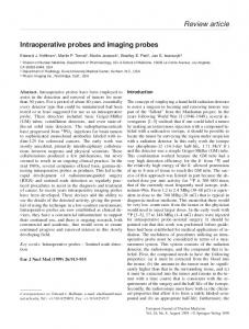
Magnetic lines of force are needed to create eddy currents in the material to be investigated. Analyzing metallic materials by ferromagnetic coils, the closer the coil, the narrower the flux lines. Ferrite is rigid and brittle. Like other ceramics, ferrite can chip and break if handled roughly. Luckily it is not as fragile as porcelain and often such chips and cracks will be merely cosmetic. Ferrite varies from silver gray to black in color. The electromagnetic properties of ferrite materials can be affected by operating conditions such as temperature, pressure, field strength, frequency and time. There are basically two varieties of ferrite: soft and hard. This is not a tactile quality but rather a magnetic characteristic. Soft ferrite does not retain significant magnetization whereas hard ferrite magnetization is considered permanent. For our applications, we have exploited a ferrite RM6-N48 produced by Epcos (see Fig. 1 for details).
Figure 1: RM6-N48-Epcos ferrite-core without the air gap and with a hole in the middle.
3. FEA APPROACH
In order to simulate the response of a probe to the presence of defects, it is necessary to study how a probe excites the specimen to be tested. Usually, the goal is the optimization of probe and the assessment of such perturbation as lift-off (from 0.3 [mm] to 1 [mm] with a step of 0.1 [mm]) and tilting (from 0 [deg]to 1.5 [deg]with a step of 0.1 deg). A FEA approach will be exploited for this purpose. A probe is placed above and parallel to a metal block. It is made of an E-profiled ferrite core, excited by a coaxial coil. In our simulations, the probe moves along the specimen at a specified speed. We verify the distortion of EC’s flux lines caused by the presence of defect and the magnetic field’s density while the probe moves over the surface. In our FEAs, since we use A-Ψ formulation [4], just the z-component of magnetic potential A is non null. Geometrical dimensions of our model are listed in Table 1. For our purpose we verified the distortion of the magnetic field density [T] [5, 6] to detect the defect presence in the specimen. In the case of quasi-static magnetic fields, Amp`ere-Maxwell’s equation can be written as: ∇×H=J (1) where H represents the magnetic field and J the current density, respectively. If we consider a moving object with velocity v relative to the reference system, the Lorentz force equation establishes
PIERS ONLINE, VOL. 6, NO. 3, 2010
239
that the force F per charge q is then given by: F =E+v×B q
(2)
where E represents the electric field; v the instantaneous velocity of the object derived from the expression of the Lorentz force and B the magnetic induction. In a conductive medium, an observer travelling with the geometry sees the current density (considering that σ is the electric conductivity) J = σ (E + v × B) + Je ; therefore, we can rewrite (1) as follows: ∇ × H = σ (E + v × B) + Je Je
(3)
[A/m2 ]
where is an externally generated current density. Considering, for a transient analysis, the definitions of magnetic vector potential A and electric scalar potential V : B=∇×A E = −∇V −
∂A ∂t
(4)
and the constitutive relationships: −1 B = µ0 µr H + Br ⇔ H = µ−1 0 µr B
(5)
where µ0 and µr are free space and relative magnetic permeability and Br is the residual magnetization. We may rewrite (3), by substituting (4) and (5) in it, as: ¡ ¢ ∂A −1 e + ∇ × µ−1 (6) 0 µr ∇ × A − Br − σv × (∇ × A) + σ∇V = J ∂t Since we are interested in perpendicular induction current, only the z-component of A is non null. Therefore, the formulation of the 3D Equation (5) is simplified to: σ
¢ ¡ ∆V ∂Az −1 + ∇ × µ−1 + Jez (7) 0 µr ∇ × Az − Br − σv × (∇ × Az ) = σ ∂t L where ∆V is the difference of electric potential and L is the thickness along the z-axis. The Partial Difference Equation (PDE) formulation of Equation (7) can be written as: σ
¢ ¡ ∆V ∂Az −1 + ∇ · µ−1 + Jez (8) 0 µr ∇Az − Br σv · ∇Az = σ ∂t L In this way we calculated the magnetic vector potential A in a generic subdomain Ω. For our aim, it is necessary to impose the boundary conditions as follows. Magnetic field (n × H = n × H0 ) for boundary of air where acting the rotating magnetic field; for remaining boundaries, included the defect, the continuity is assured by the expression n × (H1 − H2 ) = 0 [7, 8]. Table 2 resumes the values of electrical parameters. σ
Table 1: General settings of numerical models. Property Material used for the specimen Dimension of specimen Electric conductivity Diameter of the defect Height
Setting Stainless steel, not-magnetic, isotropic 100 [mm] × 40 [mm] 4.032 ∗ 106 [S/m] 2 [mm] 4 [mm]
Table 2: Electrical parameters. Parameter fexc Br Ieff v
Dimension 60 [kHz] 0.150 [mT] 100 [mA] 0.5 [m/s]
PIERS ONLINE, VOL. 6, NO. 3, 2010
240
4. IN-LAB EQUIPMENT AND RESULTS ABOUT CRACK DETECTION
Simulations carried out by FEA approach have been exploited to build a new exciting ferritecore probe for detecting cylindrical defects in stainless steel plates by means of GMR sensor [9]. According to the FEA simulations, the coil is able to sense defect presence in superficial analysis, until a depth of 4 [mm]. The best arrangement, according to FEA simulations, has been applied: lift-off 0.3 [mm] and tilting 0 [deg]. The exciting coil forms a part of a ferrite-core-ECT probe. The probe has been designed and built based upon the proposed exciting system to evaluate its efficiency and benefits. During our in-lab measurements, frequency fexc and current Ieff have been varied according to the simulations. The performances of our new ferrite-core probe have been evaluated using experimental inspection of notches in a thick stainless steel. The plate specimen inspected has a length of 100 [mm], width of 100 [mm]. The sensor has been moved over the block by means of a 0.5 [mm] step-by-step automatic scanning, along axes, in order to map the interesting area. The design of new exciting system is represented in Fig. 3. Fig. 4 shows the final result of our in-lab measurement, according to FEA simulations. Applied quantities are Iexc ' 100 [mA] with a fexc ' 60 [kHz]. The measured quantity is the voltage on the plate, converted by the GMR device from the measured magnetic field. 5
x 10-6 4
Defect depth: 6 mm Defect depth: 8 mm Defect depth: 10 mm Defect depth: 12 mm
3
3
2
2 T
T
5
Defect depth: 2 mm Defect depth: 4 mm
4
1
1
0
0
-1
-1
-2 -0.02 -0.015 -0.01 -0.005 0 0.005 0.01 0.015 0.02
-2 -0.02 -0.015 -0.01 -0.005 0 0.005 0.01 0.015 0.02
(a) B field calculated at different depths of defect
(b) Detail of numerical results for a 4 mm-deep defect
Figure 2: Numerical results obtained by FEA approach.
Surface defect Defect at 4 mm
Figure 3: General schematic representation of the detection system.
Figure 4: In-lab defect detection by GMR system.
5. CONCLUSIONS
In this paper, an implementation of ferrite-core-EC with GMR sensor for detection of defect in metallic plate is presented. For this problem, exploiting GMR sensor, a self-implemented timedependent FEA code with 2D geometries has been studied to evaluate the investigation the variation
PIERS ONLINE, VOL. 6, NO. 3, 2010
241
of magnetic flux density (in modulus). The in-lab measurements confirmed the results obtained by FEA simulations, i.e., our exciting coil is able to detect defect presence for superficial analysis until 4 [mm]. FEA procedure should be validated for defect with higher depth or different shape. Results can be exploited in order to carry out the defect reconstruction in metallic plate from in-lab experimentations. In this case, an Artificial Neural Network approach could be validate to provide a good overall accuracy in reconstructing the extension of the defect. The authors are actually engaged in this direction. REFERENCES
1. Yamada, S., M. Katou, M. Iwahara, F. P. Dawson, and S. M. Yamada, “Eddy-current testing,” IEEE Trans. Magn., Vol. 31, No. 6, 3185–3187, 1995. 2. Theodoulidis, T. P., “Model of ferrite-cored probes for eddy-current nondestructive evaluation,” J. Appl. Phys., Vol. 93, 3071–3078, 2003. 3. Fert, A., P. Grnberg, A. Barthlmy, F. Petroff, and W. Zinn, “Layered magnetic structures: Interlayer exchange coupling and giantmagnetoresistance,” J. Magn. Mater., Vol. 140, 1–8,1995. 4. Rodger, D., P. J. Leonard, and P. J. Lai, “Interfacing the general 3D A-ψ method with a thin sheet conductor,” IEEE Trans. Magn., Vol. 28, 1115–1117, 1992. 5. Koavi, R., “A study of cross-validation and bootstrap for accuracy estimation and model selection,” Proceedings of the 14th International Joint Conference on Artificial Intelligence, 1137–1143, 1995. 6. Lewis, A. M., “A theoretical model of the response of an eddy-current probe to a surfacebreaking metal fatigue crack in a flat test piece,” J. Appl. Phys., Vol. 25, 319–326, 1992. 7. Trevisan, F. and L. Kettunen, “Geometric interpretation of discrete approaches to solving magnetostatics,” IEEE Trans. Magn., Vol. 40, 361–365, 2004. 8. Tsuboi, H. and T. Misaki, “Three dimensional analysis of eddy current distribution by the boundary element method using vector variables,” IEEE Trans. Magn., Vol. 23, 3044–3046, 1997. 9. Megali, G., M. Cacciola, D. Pellican´o, and F. C. Morabito, “Recent patents on integrated software/hardware GMR-based systems and applications for PCB inspection,” Recent Patent on Electrical Engineering, Vol. 2, 82–91, 2009.