each pair of built-form portions as a tension, whose value is equally ..... tageous locations as a means to realize surplus value, although, as they are quickly.
Environment and Planning B: Planning and Design 1994, volume 21, pages 6 7 - 8 2
Modelling intraurban configurational development
R Krafta Departamento de Urbanismo, Universidade Federal do Rio Grande do Sul, rua Sarmento Leite esq. Av. Oswaldo Aranha, 90050 Porto Alegre RS, Brazil Received 31 March 1992; in revised form 25 August 1992
Abstract. A set of models for intraurban context applications is proposed that enables: (a) the description of urban configurations, by the use of simple spatial categories and concepts of areal differentiation; (b) the assessment of performance of urban configurations, by the application of centrality approaches that permit reliable correlations to behavioural aspects of urban spatial structure: depending on the comprehensiveness of the chosen models such an assessment could give a picture for the whole system or the performance of discrete components within the context of the system; (c) the potentiality and stability of configurational systems, from the point of view of change. The approach differs from mainstream urban systems studies in two ways: first, an intraurban scale was defined to suit localized and detailed experimentation, as usually found in urban design situations; second, the focus was shifted from the activity system to the configurational system, again to suit urban design processes. The research summarized in this paper gives insights into the scaling of urban phenomena, suggesting that complexity, identified in large-scale urban systems, is also present in local ones, and that urban development occurs in simultaneous, although self-similar, scales. 1 Introduction
The study of urban form has followed a variety of approaches. Conzen (1990, page 144) clarifies the basic distinction between them by defining urban morphology, in contrast to urban form: "Our view of evolving American urban structure is shaped by the market theory of urban rent. Missing in these interpretations is any consideration of the inescapable dynamics of physical city form. ... If urban form connotes a very general conception of the physical structure of cities, it would be useful to consider urban morphology as a term referring more precisely to the particular characteristics of the urban landscape; the detailed interplay of land subdivision, buildings and their combined pattern of use." In this way Conzen recognizes, on the one hand, the urban systems concept of urban form as a process, a dynamic relationship between social activities and physical devices deployed in a territory (Bertuglia et al, 1987; Crowther and Echenique, 1972). In this concept, also referred to as urban spatial structure, the physical structure tends to be considered as having a similar fluidity and obeying the same laws as that contained in and governing the functional structure of the city. On the other hand, there is the morphological concept of a relationship between physical elements of the city, defined through their spatial, as well as social and historical, characteristics. In this study urban morphology is approached from the point of view of the design process, the latter being defined (March, 1976) by three interrelated types of reasoning: productive, deductive, and inductive. In such a context, the outcome of productive reasoning is a design, or a composition; the outcome of deduction is a decomposition which comprises the characteristics of the design that emerges from analysis. Induction gives a supposition, a working rule of some generality that allows evaluation. March devised a recurrent PDI process in which a design is
68
R Krafta
produced (P) and its performance is measured (D) and assessed (I) through comparison with a given set of values. Such an assessment gives the designer the opportunity to go back to the productive reasoning with new insights. This study, therefore, is directed to the development of analytical tools which allow the adequate description of morphological properties, as well as the prediction of the performance of existing and proposed urban configurations, as a means to support better design decisions. As observed by Conzen, very little attention has been given to the particularities of physical urban form within the urban systems approach. Nevertheless, highly valuable methods and techniques, derived both from spatial interaction and from microeconomic theories, have been brought about by it, enabling the formulation of very accurate quantitative models. On the morphological side, the two major schools of conceptual thought (Slater, 1990)(1) have developed analysis techniques which, although rich in detail and very sophisticated, are not fully operational within a design context. Slater even suggests that one big challenge facing the scholars of this field is precisely how to present the research in a way in which it can be utilized by those professionals who have the responsibility for managing the development of the townscape. In this paper I report an attempt to use some of the knowledge produced by urban system studies to build models capable of describing morphological properties of urban form and to measure their performance in a systematic and operational way. Such models could then be incorporated into the design process as effective analytical tools. 2 Morphological differentiation The first step towards the quantitative modelling of urban morphological development should be the description and measurement of the performance of a given morphological state at a moment in time. This implies, first, a descriptive system based on fundamental categories and structural relationships, and, second, the identification of spatial properties through models which allow numerical measurement and accurate comparison. 2.1 Descriptive system From two basic categories, public open space and built form, an urban graph is proposed. The urban graph is a synthetic representation of urban space in which elementary portions of space are represented by dots, and the permeability or connectivity between them are represented by lines. In this way, urban graphs represent the elements of public open space, as well as built space, and their basic relationship of adjacency. Within this topological representation, different degrees of disaggregation of urban form are possible: public open space could be disaggregated into portions as small as convex spaces, or as large as entire roads. Built space, following the same pattern, could enter the graph as portions ranging from single rooms to entire buildings or group of buildings. Within the universe of all possible elementary portions of open and built space, and their combinations, four alternative urban graphs were selected for testing. In graph A open public space is represented by links and built form is represented as built form units. A link is defined as a segment of linear open public space between two adjacent intersections. A built form unit (BfU) is defined as a self-contained W These are the Anglo-German historic-geographical group, following the precepts developed by Conzen, and the Italian architectural planning group following Muratori and Caniggia. Muratori's work on the morphology of Venice can be appraised in Muratori (1959). Caniggia's theoretical construct is presented in Caniggia and Maffei (1979).
Modelling intraurban configurational development
69
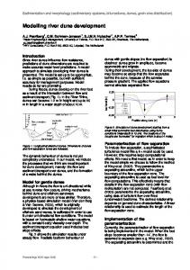
built space, such as a house, an apartment, a shop, or a factory. Graph B also represents public open space as links, although built form is expressed as front doors. This is defined as a direct permeability between buildings and public open spaces. Graph C takes public open space as axes and built form as BfUs. An axis is defined as a straight line drawn along the longest dimension of a public space. Graph D takes axes and front doors as elementary portions of space, as illustrated in figures 1 and 2.
Figure 1. Typical representation of an urban graph, taking public space as axes and built forms as front doors. Urban public space ...
reduced to lines ...
represented by graphs
Figure 2. Representation of public open space as links, axes, and graphs. Two levels of disaggregation are present in the proposed urban graphs, both for public open space and for built form. Within the realm of public space, a link is usually a small piece of urban road or street with limited variation in length; axes, on the other hand, tend to be much longer segments. Built form can be described in
70
R Krafta
terms of BfUs, which within the regularity presented by urban areas, tend to have little variation in size, or in terms of front doors which tend to encompass larger portions of floor area. The four description devices give different accounts of the density and fragmentation of public space, as well as land subdivision, land occupation, and built-form density. 2.2 Analytical models
The measurement of morphological differentiation is obtained through models based on centrality. In order to define centrality, it is necessary, first, to present the concepts of reachability and betweenness. Because every elementary portion of built form, being placed within an interconnected system of spaces, is reachable from every other portion, it is possible to identify, classify, and measure every path linking an unordered pair of built-form portions. The following situations arise. (a) Two built-form portions are reachable directly, without the use of any public space. This is not considered an urban case, in the sense that the relationship between these two elementary built spaces does not affect the public dimension of the city. (b) Two built-form portions are reachable through one single public space. This is a case in which the two built-form portions are located on the same public space. (c) The reachability between two built-form portions involves more than one public space, in which case one or more paths between them are possible. This case introduces the idea of betweenness. Freeman (1977, page 35) observes that "The earliest intuitive notion of point centrality was based upon the structural property of betweenness. According to this view, a point in a communication network is central to the extent that it falls on the shortest path between pairs of other points". Among all possible routes linking a pair of built-form portions one or more will be the shortest, and the public open spaces which are part of these routes are central. Consequently, centrality could be defined as a property of public spaces consisting of the capacity of falling on the shortest routes between every pair of built-form portions in a particular urban system. The most central space will be the one which falls on the largest number of shortest paths in the system. In the proposed model this centrality is measured by considering the relationship between each pair of built-form portions as a tension, whose value is equally distributed among all public spaces which form the shortest path(s) linking these built-form portions. The sum of all bits of tension generated by all pairs of built-form portions gives a general measure of centrality. Centrality is proposed as a property of public space, although it is generated through the relationship between built-form portions. The fact that centrality is related to public spaces which are 'loaded' with a number of built-form portions holding the same topological address introduces simplified calculation, to the extent that all built-form portions belonging to one space have the same relationship with all built-form portions belonging to another space. The algorithm for measuring centrality involves three steps. The first is the identification and elimination of all tensions not affecting urban public spaces, that is, tensions generated by pairs of built-form portions which are directly interconnected. The second step is to identify and calculate the inner tension, that is, the tension generated by pairs of built-form portions located on the same public open space. Inner tension, t1, is given by a simple combinatorial calculation of n pairs of built-form portions:
,I = n(£zi).
(1)
Modelling intraurban configurational development
71
The third step is to calculate the tension which affects more than one public space. The entire network formed by all public spaces (represented by dots) and their connectivity must be processed in order to identify all shortest paths linking pairs of spaces. Tension generated by all pairs of built-form portions placed on different public spaces is allocated to shortest paths according to the condition: %=
M
, (2) n in which tif is the tension between all built-form portions located on spaces i and /', ft and fj are the number of built-form portions in / and /, and n is the number of shortest paths linking / and/. The tension between individual spaces belonging to these shortest paths is distributed according to tiJ(k) = f^-p, (3) n where ty(k) is the fraction of ttj- allocated to space k, and p is the number of times space k falls on the shortest paths between spaces / and j . According to this, if there is just one shortest path between spaces i and /, the tension will be equally distributed between all spaces belonging to it, including / and /. If there are two shortest paths and space k falls on both, it will be assigned twice as much tension as the others, and so on. The overall tension of each space can be identified by summing all bits of tension allocated to it throughout the distribution procedure related above:
t(k) = ttii(k).
(4)
i