machines in cars. In this paper you will find a short introduction of how to model
an electrical machine and their most common failures. The modelling is done in ...
SIMS 2007
Modelling of Electrical Faults in Induction Machines Using Modelica R
Dietmar Winkler Clemens Gühmann Technische Universität Berlin Department of Electronic Measurement and Diagnostic Technology {Dietmar.Winkler|Clemens.Guehmann}@TU-Berlin.de
Abstract
Because of the (in most hybrid architectures) rigid connection of the electric drive with the cars drivetrain, electrical failures result in a direct mechanical impact via torque changes. Depending on the type of hybridisation (e.g., micro-, mild-, or full-hybrid) the effect might vary from an inconvenient torque loss to a full traction-loss. The impact can even become quite critical if we consider the use of in-wheelmotors which might even lead to accidents. With the help of modelling and simulation of electrical machines some of the possible dangers can be investigated and appropriate control strategies can be developed to minimise the failure-impacts. This work will show the development of induction machine models using the object-oriented modelling language Modelica R (for more on modelling with Modelica R see [2, 3].
This paper presents the modelling of electric faults in induction machines using Modelica R as modelling language. The primal application for such fault simulations is the ever increasing application of electric machines in cars. In this paper you will find a short introduction of how to model an electrical machine and their most common failures. The modelling is done in the phases reference frame rather than in a field-oriented reference frame. The reason for this is given in this paper. The simulation models work and simulation results are given. The verification of the simulation results with a motor test-bench is still an outstanding task at which we are currently working on. Keywords: Modelica, electrical machines, modelling, fault simulation, field-oriented control
2 1
Introduction
Mathematical fundamentals of electrical induction machines
The classic approach to describe an electrical machine is by the use of the so called equivalent phase circuit diagram. In the following the machine equations shall be explained taking an asynchronous induction machine as an example. There are however much similarities to the synchronous machine which shall not be investigated further in this short paper (see for example [4]). Figure 1 represents the equivalent circuit for one phase of the electrical machine. It consists of resistances representing the ohmic losses in the field windings (Rs and Rr ) and the stray inductance (Lsσ and Lrσ ) in the stator and the rotor. The rotor and stator are coupled via the mutual inductance (Lm ). The standard machine equations for the rotor and sta-
It has been ten years now since Toyota released its first version Prius I. Since then the number of hybrid electric vehicles has been continuously growing which in turn means that a new ever growing market for electric drives has emerged. This new marked pushed the development efforts in various field of engineering. For one, different control strategies for the electric drive are needed in order to use the electric power as efficient as possible. Thus being able to save as much petrol as possible when driving from A to B [1]. The application of electric drives in cars also raised various safety-related issues. There lies a great interest in investigating the possible impact of failures of electric machines on the cars driving behaviour.
82
Rs
Lsσ
Lrσ
Lm
Vs
the coupling effect depends on the rotor position γ. For a three phase machine (m = 3) this gives:
Rr
Lsr (γ) = [Lrs (γ)]T (7) 2 2 cos(γ) cos(γ + 3 π) cos(γ − 3 π) = cos(γ − 32 π) cos(γ) cos(γ + 23 π) cos(γ) cos(γ + 32 π) cos(γ − 23 π) (8)
Vr
Figure 1: Equivalent circuit diagram of electrical induction machine
2.1
At this stage normally the field-oriented control is introduced. The idea of the field-oriented control is to transform the three (or m) phases into an orthogonal system consisting only of two resulting space vectors (dq-frame). Depending on the application these vectors can then be aligned for example to the stator, or the rotor flux. This gives the benefit that instead of having to calculate three (or m) time variant interdependent stator currents, for example, only two currents have to be calculated. These can also be controlled independently and are constant during steady state operations. This technique can improve the simulation speed considerably. Since all the transformation matrices are quite complex and are not the focus of this paper, the field-oriented control is not described any further. The interested reader can find various papers and books on this topic. Two of theses are for example [4] and [5].
tor voltages can be written as: d~is d~Ψms + dt dt ~ ~ dir dΨmr ~vr = Rr~ir + Lrσ + dt dt ~vs = Rs~is + Lsσ
(1) (2)
where Ψmx are the flux vectors and defined as ~Ψms = Lss ·~is + Lsr (γ) ·~ir ~Ψmr = Lrs (γ) ·~is + Lrr ·~ir
(3) (4)
In the equations (3) and (4) you can see the four inductance matrices. Each of these have the dimension (m × m) where m stands for the number of phases (three in most cases). Lss and Lrr represent the selfinductance matrices for the stator and the rotor, respectively.
2.2
Lm Lsm Lsm Lss = Lsm Lm Lsm Lsm Lsm Lm
Reason for not using FOC
As much as the field-oriented control can improve the simulation speed, the simulation models itself become quite abstract. When it comes to simulating some physical errors of the machine in order to gain some information on the impact such an error would have, field-oriented models are not the first choice.
(5)
and Lm Lrm Lrm Lrr = Lrm Lm Lrm Lrm Lrm Lm
Field-oriented control (FOC)
(6)
Example: Let’s take an example to explain the drawback of field-oriented control for error simulation. In an induction machine we have got a shortcircuit of one or more stator windings. This would result in a different stator resistance and inductance. Since in our field-oriented model only consists of the transformed and combined components we than have to also transform the stator error from the (let’s say) three phase system to the orthogonal system. But this also means that our machine model is not symmetrical anymore and we have to take care that all previous transformations from the three phase system to the orthogonal system are still valid (some actually
If the the machine is symmetrically built than the matrices can be simplified further by providing the equations: 2 Lsm = Lrm = Lm · cos( π) m This also means that stator and rotor self-inductance would be identically. We still got the two matrices Lsr (γ) and Lrs (γ) left. These represent the mutual coupling between the stator and the rotor side and vice versa. Unfortunately
83
require symmetrical systems as a prerequisite). Finally we end up with an orthogonal model which is unsymmetrical and therefor has time depending variables even for steady state operations. So for this kind of error simulation the benefit of reduced simulations times is not present any more and moreover we still have the abstract representation of the error values in the orthogonal system. Because of this reason, in this paper the modelling is done in the m-phase domain rather then the orthogonal system. Mind you, the control of the electrical machine would still be done field-oriented. Just the model is not transformed. This also corresponds with the real life where we got an field-oriented controller giving control signals to an inverter-bridge which in turn then provides the m-phase voltages and currents.
3
Machine models in Modelica R
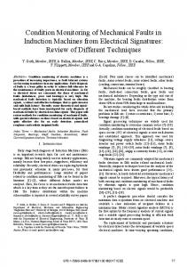
The free available Modelica Standard Library (MSL[6]) already contains basic machine models[7]. Unfortunately these models are only suitable for modelling symmetrical electrical machines by using dq-frame-oriented parameters. An electrical fault in one of the phase windings (stator or rotor) leads however to unbalanced machine equations which are not used by the basic machine models of the MSL. So different models have to be developed to take the unbalanced behaviour into account. This leads to a more complicated model than the normally used field-oriented dq-model. Such models of unbalanced electrical machines are presently part of the ongoing development of a free and open-source Modelica R library called freeFOClib[8] (short for free FieldOriented Control library) at our department. When developing the new models for error simulation it was desirable to use as much from the standard components from the MSL in order to keep the library as slim as possible. For the modelling of an asynchronous induction machine with squirrel-cage in a three-phase system all components which are not rotor-angle dependent could be modelled using standard components from the MultiPhase sub-library of the MSL. Also when no errors in the squirrel-cage part are introduced than the standard field-oriented model of the squirrel cage can be used. In Figure 2 a screen shot from the graphical representation in Dymola (modelling and simulation tool of Dynasim AB, Sweden) of such a system is depicted. All the rotor angle dependent matrices are modelled in Modelica code within the model airGap3Phase.
Figure 2: Graphical model representation of a 3phase asynchronous machine with squirrel cage
It follows an excerpt of the source code of the airGap3Phase model which is used to build the matrices in equation (5) trough to equation (8):
1 Lss = fill(fill(Lsm, 3), 3) diagonal(fill(Lsm - Lm, 3)); 2 Lrr = Lss; 3 Lsr = Lm .* {{cos(gamma),cos(gamma 2/3*pi),cos(gamma + 2/3*pi)}, 4
{cos(gamma +
2/3*pi),cos(gamma),cos(gamma - 2/3*pi)}, 5
{cos(gamma -
2/3*pi),cos(gamma + 2/3*pi),cos(gamma)}}; 6 Lrs = transpose(Lsr);
The mutual fluxes and the resulting voltages are then calculated by:
84
1
// mutual fluxes:
2
psi_ms = Lss*i_s + Lsr*i_r;
3
psi_mr = Lrs*i_s + Lrr*i_r;
4 // mutual voltages: 5
v_ms = der(psi_ms);
6
v_mr = der(psi_mr);
4
Fault simulation
this would be some kind of fuse. In the fault-models of the freeFOClib also fuses are implemented.
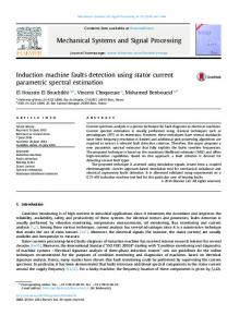
After a brief introduction of how the the machines are modelled in a m-phase system we will now come to that actual application, i.e. the fault simulation. 4.1 Open-circuit fault At first let us see which different fault scenarios are Here now comes an example simulation of a synlikely chronous machine having a open-circuit fault. This Typical examples are: could occur if a connecting cable comes loose. In • open-circuit of a stator phase (e.g., a connecting Figure 3 you can see the three phase currents and the mechanical torque depicted over time just before and cable is broken) after the connection of one phase was opened at the • short-circuit phase to ground (e.g., insulation time of two seconds. failure because of mechanical damage) Torque 250
• short-circuit of one or more phase windings (e.g., insulation failure because of thermal stress within the stator or rotor)
T [Nm]
200
Theses faults would then again have an influence on the:
100
50
0 1.4
1.5
1.6
1.7
1.8
1.9
2
2.1
2.2
2.3
2
2.1
2.2
2.3
Time [s] Currents
• mechanic torque (e.g. which has a direct impact on the drive train behaviour in a hybrid electric vehicle)
200 150 100
i [A]
50 0 -50
• emerging voltages and currents (which might damage the power electronic devices supplying the electric motor) In order to generate these faults we need an interface to our model to trigger the fault. The first two faults (open-circuit and short circuit) can be achieved by introducing an electrical switch which then closes or opens the corresponding phase connection. Since our model is modelled in the physical phase domain the implementation of this is pretty straight forward. However the third fault (short-circuit of one or more phase windings) requires a change in the air-gap model. To be more specific, the way the inductance matrices are built has be altered. In our we have chosen to use an input variable into which the faulty inductance matrices can be fed. The switch from a normal to a faulty inductance is realised by a timetriggered ramp function. The slope of the inductance change can be configured as well as the switching time. It is also possible to reduce the normal inductance value by a specific amount (say 10% for example). Furthermore in a real application there would be some kind of guidance control to avoid any damage to the machine or inverter. Very simply speaking,
150
-100 -150 -200 1.4
1.5
1.6
1.7
1.8
1.9
Time [s]
Figure 3: Fault scenario: open-circuit of one stator phase
As you can see, the torque drops instantaneously and but the controller try to keep the torque output until at some point the fuses for the remaining phase currents get triggered.
4.2
Short-circuit fault
This kind of fault can occur when the insulation of the connection cables is somehow damaged. In Figure 4 again you can see the three phase currents and the mechanical torque depicted over time just before and after one phase winding connects to ground at the time of two seconds. Again the controller tries to keep the torque at a constant level but can only do so for a certain amount of time until the the fuse finally gets triggered.
85
Torque
Torque
80
200
70
50 T [Nm]
T [Nm]
60
100
0
40 30 20
-100 1.6
1.8
2
2.2 Time [s] Currents
2.4
2.6
10 0
200
2
2.5
3
3.5
4
4.5
5
4
4.5
5
Time [s] Currents 100
100 i [A]
50
i [A]
0
-100
-200
0
-50
-100
1.6
1.8
2
2.2 Time [s]
2.4
2.6
2
2.5
3
3.5
Time [s]
Figure 4: Fault scenario: short-circuit of one stator Figure 5: Fault scenario: short-circuit of phase windings phase to ground
We presented some ways of how to implement the different fault scenarios and also included some simThis kind of fault can occur when the insulation be- ulation results. tween the phase windings is damaged (e.g., overtemperature, overload, etc.). This behaviour is modelled by reducing the inductance abruptly by 20 per- 6 Future work cent. In Figure 5 you can see the three phase currents and the mechanical torque over time just before and The developed models of unbalanced electrical maafter the connection of one phase was opened at the chines areRgoing to be a part of a free and open-source Modelica library called freeFOClib[8] (short for time of two seconds. As you can see this time the change in the currents free Field-Oriented Control library). The first official is not that drastic. However since the field-oriented release is due in spring of 2008. The freeFOClib control now calculates the wrong control values the will also contain all components which are necessary for a field-oriented control (hence the name). The torque starts to oscillate. idea is to provide a Modelica R library which gives the possibility to model a modern electrical drive system and still leaves the user the freedom to look at 5 Conclusions the underlying code and perhaps even contribute imIn this paper a the modelling and simulation of elec- provements to freeFOClib. tric faults in electrical machines using Modelica R A pure estimate of the simulated values might give was presented. The reader could get a brief in- some clues on the general behaviour during faults. troduction into the topic of modelling electrical in- However to actually use the simulation to gain useduction machines in general. By using the object- ful information (e.g., for programming a controller oriented language Modelica R it is possible to keep for the power electronics) we need more than just esthe new models compact by making use of the inher- timates. So the simulation model has to be verified itance mechanism in connection with the free avail- by doing real measurements using a real electric moable Modelica Standard Library. Extensive usage of tor. At the moment we setting up a test-bench sysinheritance also means that the maintenance is sim- tem consisting of a asynchronous induction machine pler than if one bit of code is used in several places. of a currently available hybrid electric vehicle and
4.3
Short-circuit of windings
86
an electrical load machine. Although we hoped to be able to include some measurement results from the test-bench already, unfortunately it was not feasible for this paper. Still we are working hard on the further development of the library and the verification with the test-bench system. For any news on the freeFOClib library see www.freefoclib.org. On that site also a mailinglist is available to keep you automatically up to date.
References [1] D. Winkler and C. Gühmann, “Hardware-in-theLoop simulation of a hybrid electric vehicle using Modelica/Dymola,” in The 22nd International Battery, Hybrid and Fuel Cell Electric Vehicle Symposium & Exposition (E. . Secretariat, ed.), (Yokohama, Japan), pp. 1054–1063, EVS, Japan Automobile Research Institute, 23-28 October 2006. [2] P. A. Fritzson, Principles of Object-Oriented Modeling and Simulation with Modelica 2.1. No. 0-471-471631, John Wiley & Sons, Januar 2004. [3] M. Tiller, Introduction to Physical Modeling with Modelica. Kluwer International Series in Engineering & Computer Science, Kluwer Academic Publishers, 2001. [4] D. Novotny and T. Lipo, Vector Control and Dynamics of AC Drives. Clarendon Press Oxford, 1996. [5] W. Leonhard, Control of Electrical Drives. Springer, 3rd ed., 2001. [6] Modelica Association, Modelica R - Free library from the Modelica Association, version 2.2.2 ed., 31st August 2007. [7] C. Kral and A. Haumer, “Modelica libraries for dc machines, three phase and polyphase machines,” in Proceedings of the 4th International Modelica Conference (G. Schmitz, ed.), pp. 549– 558, Modelica Association, March 7-8 2005. [8] D. Winkler, E. Bakhach, F. Döring, and S. Rinderer, “freeFOClib - A free Field-
87
Oriented Control library for Modelica.” unreleased, see www.freefoclib.org for any news. Due in, Spring 2008.