MODERN MOBILE MAPPING: ON-THE-FLY IMAGE PROCESSING Charles K. Toth and Dorota A. Grejner-Brzezinska§ Center for Mapping Department of Civil and Environmental Engineering and Geodetic Science§ The Ohio State University 1216 Kinnear Road, Columbus, OH 43212-1154 Phone: 1 614-292-7681 Fax: 1 614-292-8062 E-mail:
[email protected]
KEY WORDS: GPS, INS, CCD, Image sequences, Real-time processing
ABSTRACT Mobile Mapping Systems have been widely used to map transportation infrastructure features for several years. The data acquisition objective of these surveys is typically twofold: to collect an inventory of various, mostly man-made, objects and then to position them in a local frame. First generation Mobile Mapping Systems, however, could not provide positioning accuracy better than one meter, especially in built-up urban areas. Thus, these data sets have been predominantly used to feed various GIS systems, primarily concerned with infrastructure inventory and facility management. With recent technological developments such as improving imaging sensors and, more importantly, the introduction of ring-laser gyro inertial systems, the performance of current Mobile Mapping Systems can reach the cm-level, which, in turn, opens up the field of the engineering applications, which are more demanding in terms of positioning requirements. The Ohio State University is currently developing a GPS/INS/CCD integrated system for precise (centimeter level) monitoring of highway center and edge lines, sponsored by the Ohio Department of Transportation. The prototype-positioning component of the system is based on a tightly integrated GPS/INS system, and the imaging component comprises a single downlooking high-resolution, 1K by 1K, digital camera. The high image rate (up to 15 frames per second) provides sufficient overlap of the subsequent images at highway speed, and thus, it allows for stereo data processing, which, to a large extent, is expected to be performed in realtime with the support of on-the-fly navigation solution. The focus of this paper is on the design, calibration, and preliminary performance analysis of the prototype system. The application of the navigation data to real-time image processing represents a new approach. The process of automatically identifying centerlines, extracting image features and matching them is demonstrated on a variety of data sets, indicating clearly that the algorithmic performance has reached a sufficient threshold such that human interaction is no longer required, and consequently, the only limiting condition of the real-time implementation is the available computer processing power.
INTRODUCTION Direct georeferencing of imaging sensors by means of integrated GPS/INS has been in the spotlight in the surveying/mapping and remote sensing communities since the mid-nineties (He et al., 1994; Bossler and Toth, 1995; El-Sheimy and Schwarz, 1999; Schwarz, 1995). One reason is that the primary driving force behind this process is a need to accommodate the new spatial data sensors, such as LIDAR or SAR (airborne systems). The second reason is that a substantial cost decrease, a possibility of data reduction automation, and a short turn-around time are the most attractive features offered by this technology. The Ohio State University has long been involved in MMS system developments and currently is developing a dedicated system for precise (centimeter level) monitoring of highway center and edge lines. The prototype-positioning component of the system is based on a tight GPS/INS coupling, and the imaging component comprises a single down-looking, high-performance color digital camera. The main features of the system are the high image capture rate, the online use of navigation estimates, and the on-the-fly image and stereo data processing. From a navigation standpoint, the post processing of GPS/INS data provides more accurate orientation as a benefit of forward and backward trajectory processing and precisely synchronized timing information. However, some navigation data available in real-time (such as relative image orientation) can efficiently support the processing of the image sequences on-the-fly by extracting and storing only the necessary information, as opposed to the entire image (if only simple features, such as linear objects are needed). Obviously, further postprocessing can rectify the positioning and orientation data that should subsequently be used to provide precise georeferencing to the features extracted in real time. This procedure adds more robustness to the system, allowing faster and more automatic data processing, saves storage space and processing time, as data acquisition can be combined with the image pre-processing. The high-accuracy GPS/INS/CCD system designed for monitoring linear highway features is based on the concept of tight sensor integration, combining post-processing with real-time image processing. The two primary components of the mobile mapping system currently being implemented are precise navigation and digital imaging; both allow for flexible and optimal system design, leading potentially to near-real time overall data processing. The navigation component, in essence, follows the structure of the AIMS system, developed earlier at the Center for Mapping, OSU (Toth, 1997). The imaging system provides the much-needed connection between the high-precision vehicle navigation data and the marks on the road surface, thus relieving the driver from the stress of having to drive a pivot wheel precisely on the lines as former mechanical systems required. Primarily for economic reasons, the processing of the images must be automated, and preferably performed in real-time. Under ideal conditions, the centerline offset from the vehicle position can be easily obtained from monoscopical image measurements, provided the vehicle geometry and the camera model are known. Vehicle position/attitude changes due to its motion and road unevenness, however, introduce at the same time non-negligible errors in this model. To compensate for these errors, a stereo technique can be used, which can be easily achieved by acquiring overlapped imagery. Since a single camera collects images, the stereovision is realized by the platform motion, which, in turn, emphasizes the need for high-precision sensor orientation.
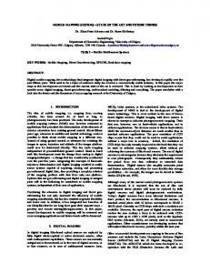
SYSTEM CONCEPT Mobile Mapping Systems are built on the concept of combining high-performance georeferencing with electronic imaging on a moving platform. In land-based mapping applications, digital cameras are mounted on the roof of the vehicle and images are collected proportionally to image sensor or vehicle motion, typically reaching a data acquisition rate of a few images per second. Although such configuration allows for road centerline extraction, it is far from being optimal for this task. Therefore, we propose a solution, which is completely dedicated to address the centerline extraction by optimising all the steps of the sensor integration, including hardware, data acquisition, and algorithmic processing. MMS systems have been using image sequences for a long time since it is an essential part of the concept. However, progress toward the automation of the image sequence processing has been slow for two reasons. First, economy; the actual feature extraction represents approximately less than 20% of the overall cost, and therefore, the financial motivation is weak. Second is the varying image scale, which makes the object recognition task quite difficult in the feature-rich object space. Typically, earlier experimental methods have worked in post-processing mode and required non-negligible user interactions (Habib, 2000). The centerline extraction in our approach, however, represents a much more forgiving task from the automated image processing view because due to the special sensor arrangement the image scale changes are limited and the image contents are rather well defined. Traditional MMS systems work with forward- or side-looking cameras, while our system uses a down-looking camera, with an image sensor plane almost parallel to the road surface. This way the image scale changes very slightly and there is an almost constant scale along the vehicle trajectory. To compensate for the smaller footprint, the image covers the road area of about that of a vehicle; however, the image capture rate should be increased. The object contents of the images are rather simple and predictable, such as the line marks, the primary interest to us, surface texture variations, cracks, potholes, skid marks, etc. Therefore, extracting features from a well-defined set of possible objects from an almost constant scale imagery constitutes a much more formidable task compared to the generic MMS approach. Consequently, a large number of proven computer vision methods can be successfully applied for object extraction. Figure 1 shows the generic model of the dedicated centerline mapping system.
ω
GPS Antenna
Digital Camera
ZINS
INS -YINS
H
Y Figure 1. Sensor geometry of the centerline mapping system.
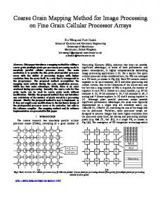
HARDWARE IMPLEMENTATION The prototype of the integrated GPS/INS/CCD system designed for precision monitoring of the highway edge- and centerlines comprises two dual-frequency Trimble 4000SSI GPS receivers and a medium-accuracy and high-reliability strapdown Litton LN-100 inertial navigation system, based on Zero-lockTM Laser Gyro (ZLGTM) and A-4 accelerometer triad (0.8 nmi/h CEP, gyro bias – 0.003°/h, accelerometer bias – 25µg). The LN100 firmware version used in this project allows for access to the raw IMU data, with an update rate up to 256 Hz. Estimation of errors in position, velocity, and attitude, as well as errors in inertial and GPS measurements, is accomplished by a 21-state centralized Kalman filter that processes GPS L1/L2 phase observable in double-differenced mode together with the INS strapdown navigation solution. The estimated standard deviations are at the level of 2-3 cm for position coordinates, and 5-7 arcsec and ~10 arcsec for attitude and heading components, respectively. The imaging component is built around the Basler A201 camera, Kodak 1K by 1K colour CCD with 9.07 mm by 9.16 mm imaging area (9-micron pixel size) and 15 images per second acquisition rate (15 Hz), which allows for 60% image overlap at normal highway speed. For testing and performance evaluation of the positioning component, a digital camera based on a 4K by 4K CCD with 60 by 60 mm imaging area (15 micron pixel size), manufactured by Lockheed Martin Fairchild Semiconductors was used. The imaging sensor of this experimental configuration is integrated into a camera-back (BigShot™) of a regular Hasselblad 553 ELX camera body, and the camera is installed on a rigid mount together with the INS (Toth, 1998).
Base GPS Station
LN-100 INS
Rover GPS Station
Delta V Delta=θ=
L1 and L2 Time Tag/Sync
Basler A201 1K by 1K Camera
Centerline Postprocessing Module
L1 and L2 phase observable
Image Data Exposure Control
Strapdown Navigation Solution Tightly Coupled GPS/INS Kalman Flr
Optimal Position, Velocity, Attitude Estimates
User Interface, Control & Display Unit
Control Signal EO Data
Image Acquisition Control and Storage
Host/Slave Real-time CommunicationImage Processing Module
Figure 2. Sensor integration and dataflow block diagram.
Figure 2 shows the system design, including the sensors, dataflow, processing steps. Except for the real-time image processing module, it is similar to the AIMS system mentioned earlier and was presented in (Grejner-Brzezinska et al., 1998; and Toth and GrejnerBrzezinska, 1998).
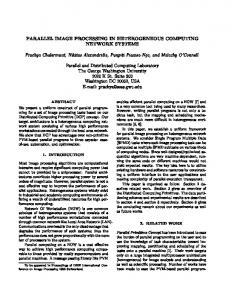
PERFORMANCE OF THE AUTOMATED IMAGE SEQUENCE PROCESSING To assess the feasibility of automated line extraction with 3D positioning and consequently its real-time realization, a rich set of the potential image processing functions was developed in a standard C++ programming environment. Figure 3 shows the overall dataflow and processing steps, which will be illustrated in more detail later. In short, the real-time image processing is feasible due to a simple sensor geometry and the limited complexity of the imagery collected. Data Acquisition
Image Preprocessing
Image n-1
Image n
RGB to S Transformation
RGB to S Transformation
Median Filter Binary Conversion
Median Filter Binary Conversion
Boundary Points Centerline Extraction
Boundary Points Centerline Extraction
Feature Point Extraction
Feature Point Extraction
Relative Motion Estimates
Feature Point Matching
Stereo Image Processing
Affine Model Formation Centerline Strip Formation
Post-processing
Centerline Position Refinement
Final Navigation Data
Export to GIS/CAD
Figure3. Real-time image processing and post-processing workflow. First, a single down-looking camera acquires consecutive images with about 50% overlap, which cover only the road surface to the side of the vehicle. Then centerlines are extracted from the images, followed by feature point extraction around the centerline area. Finally, the feature points are matched to build a strip from the images. This matching process is greatly facilitated by the simultaneous availability of navigation data; basically the change in position and attitude between two image captures – relative orientation – has a dramatic impact on the search time for conjugate entities on image pairs since the usually two-dimensional search space is reduced to one dimension.
Color Space Transformation Traffic signs, centerlines and the like have distinct colors to draw attention of drivers in an unambiguous way. Therefore, color images are preferred over monochromatic ones. Figure 4 illustrates various cases, including an extreme situation where the yellow solid lines are hardly visible in the B/W image. A simple histogram analysis in the RGB (Red, Green, Blue) color space easily reveals two peaks in the red and green channels representing the yellow color of the centerline.
Figure 4. Centerlines of various qualities. Although there are many image processing algorithms working with various color data (multichannel gray-scale imagery), the great majority of the core functions work only on simple monochrome image data. Therefore, if possible, a color space conversion is desirable, in other words, moving from the 3D color space into one dimension, a color direction, which shows the best possible separation for the objects we want to distinguish. For example, moving from RGB to IHS (Intensity, Hue, Saturation) space can effectively decouple intensity and color information. After some experiments, we decided to use an RGB to S transformation, which is illustrated in Figures 5 under various road conditions. Obviously, dealing with one channel has a major benefit for the real-time implementation.
Figure 5. Test images and their RGB-to-S transformed representations.
Since the quality of the extracted centerlines still show visible differences, a filtering process has been implemented to remove this dissimilarity. The output of the median filter is converted to a binary image. End results show no significant difference between the centerline segments extracted from the very different images as illustrated in Figure 6.
Figure 6. Final output of the color transformation process. Centerline Extraction After the RGB to S transformation and filtering, the geometry of the centerlines is extracted from the binary images. Under the given dimensions of the mapping vehicle and the geometry of the camera, the centerlines, in transportation terms, are showing up in the images as multipixel-width lines (20-30 pixels wide), usually referred to as raster line in the vision community. For a raster line, its centerline is of primary interest. In literature, similar terms such as skeleton (Pavlidis, 1982; Murthy, 1974; Nguyen, 1986), or medial line (medial axis) (Montanvert, 1986) are used. Skeleton is more like a one-pixel-width line, while centerline can be used to express a one-pixel-width line in both raster and vector lines. The mathematical definition of the centerlines of a raster line varies depending on the algorithms used to generate the centerline. In thinning algorithms, the skeleton is a collection of such pixels, which has more than one nearest neighbor to the boundary of a raster line (Pavlidis, 1982). The skeleton is then extracted by shrinking the raster line from its boundary in all directions until the one-pixel-width eight-connected line remains. In the medial axis transformation method (Montanvert, 1986), the discrete medial axis pixels are the local maximum of a transformation value. For centerline extraction, we selected a scan line-oriented method, which is simple and executes faster than most other algorithms. In this one-pass process, the computation is linear to the number of pixels on a raster line. Taking advantage of the known centerline direction, the optimal scan line direction, which is perpendicular to the centerline, can be easily achieved for most situations. During the scanning, the pixels along a scan line, which is a small segment of an image column, are processed in a top-to-down fashion. A robust recursive filtering technique can eliminate noise such as gaps, although most of the gaps and grey-scale irregularities already have been removed during the color space transformation, as well as provide segmentation for multiple centerlines such as double solid lines. Figure 7 depicts the results of this processing step. Once boundary points are extracted, a line-following routine can generate the boundary lines, which are subject of further cleaning such as removing irregularities by applying geometrical constraints. In the final step, the midpoints are computed and the centerline is extracted as shown in Figure 8.
Figure 7. Centerline boundary points extracted.
Figure 8. Automatically extracted centerlines. Feature Point Extraction To achieve the highest accuracy possible, the 3-dimensional centerline positions must be obtained from stereo imagery. Knowing the camera orientation, both interior and exterior, and the matching (identical) entities between the 2-dimensional centerlines, the 3-dimensional centerline position can be easily computed. Since the external orientation is provided by the navigation data, and similarly the interior orientation can be determined by a priori calibration, the primary task is reduced to finding conjugate points or features in overlapping images. Since centerlines are subject to shift invariance, they cannot be used directly for matching purposes. There are a number of methods used for image matching, including feature-based and area-based techniques (Toth and Schenk, 1992). Because of the special condition of the object space – near parallel planes – a simple correlation-based area method seems to be adequate for this purpose. For matching image primitives, feature points are considered. Feature points correspond to high curvature or high gray level variety points. For simplicity, a corner detector, devised by Harris and Stephens was selected to extract feature points, which is based on the following operator: R( x, y ) = det[C ] − k ⋅ trace [C ] 2
é ^2 I C = ê ^x ê êë I x I y
^
IxIy
ù
^
I y2
I denotes the smoothing operation on the grey level image I(x, y). Ix and Iy indicate the x and y directional derivatives respectively. Figure 9 depicts feature points extracted around the centerline region from overlapping images.
Figure 9. Feature points extracted. Matching Feature Points The matching of the feature points is accomplished through correlation. The search space is constrained by the availability of epipolar geometry. For a given feature point s, a correlation window of size n×m is centered at its location in the first image, at point s1. Then a search window around the approximated location of the same object point s in the second image is selected, point s2, and the correlation operation is performed along the epipolar line. The search window size and location are determined by navigation data. The correlation score is defined as c( s1 , s 2 ) = λ
n
m
i =1 j =1
[ I 1 (u1 + i, v1 + j ) − I 1 (u1 , v1 )][ I 2 (u 2 + i, v 2 + j ) − I 2 (u 2 , v 2 )]
Where Ik(uk, vk) is the average at point (uk, vk) of Ik (k=1, 2), and λ is a normalizing factor so that the score ranges from –1, for two correlation windows which are not similar at all, to 1, for two correlation windows which are identical. A point in the first image may be paired to several points in the second image. Several techniques exist for resolving the matching ambiguities. Due to the special case scenario of a near planar object surface, a 6-parameter affine transformation provides an adequate geometrical relation between two images. Therefore, by calculating the affine transformation parameters by conjugate points, straightforward blunder detection can be used effectively for disambiguating matches and removing outliers. Strip Formation After determining the transformation parameters between consecutive images, the centerline segments are connected and an approximate centerline can be incrementally formed. However, the final coordinates of centerline can be computed only in post-processing mode once the final navigation data have become available. To illustrate the fit between images, an image strip was built by transforming five consecutive images into the same frame as shown in Figure 10.
Figure 10. Automatically formed image strip.
POSITIONING PERFORMANCE The multisensor system calibration is a key task to achieving the ultimate accuracy of the given sensors. System calibration is defined here as the determination of spatial and rotational offsets between the sensors (GPS/INS lever arm and INS/camera boresight misalignments) as well as imaging sensor calibration. Continuous calibration of the INS system is provided by GPS and thus is very dependent on GPS anomalies such as satellite signal obstructions, multipath, interference, etc. To demonstrate the importance of proper system calibration, the boresight misalignment determination and the overall accuracy assessment are briefly discussed here. For system calibration and for performance assessment of the positioning component, a 4K by 4K digital-sensor equipped Hasselblad camera with a 50-mm focal length lens, tilted downwards by 5°, was mounted rigidly on the top of the LN100 in side-looking position; the offset from the GPS antenna was about ~1 m. Imagery with various overlap was collected at a calibration wall and along a surveyed road in several passes. The effective ground pixel size was about 2-4 mm. Figure 11 shows the calibration range, and the road area with control points.
Figure 11. Calibration range and road test site images. A comprehensive analysis of the system calibration and positioning performance are available in (Grejner-Brzezinska and Toth, 1999, and 2000). In a nutshell, the aerial triangulation for the calibration range resulted in less than one cm residuals for the photo centers. Differencing the exterior orientation data with the navigation solution resulted in the boresight misalignment for the digital camera with about 2-3 cm offset and about 20 arcsec attitude accuracy, clearly indicating that the positioning component is dominating the error budget. Using these boresight parameters, the comparison of ground coordinates obtained by the photogrammetric methods from the directly oriented imagery to the GPS-measured ground truth delivered the ultimate accuracy performance of the overall system. The control points used in this test were
GPS-measured with an accuracy of ~1.5 cm per coordinate and were located about 18 m from the perspective center of the camera. The comparison between the ground truth and the photgrammetrically-derived coordinates showed about less than 3 cm differences. Finally, highway tests indicated that loss of lock is the single most critical threat to maintaining consistent performance. In fact, that is the primary reason why a high-performance INS was selected, as it can effectively bridge the gaps when GPS data are not available. The INS attitude performance is not that critical for the imaging sensor due the rather large photo scale.
SUMMARY AND CONCLUSION This paper introduced a concept of an all-digital mapping system designed for precise mapping of highway linear features. The test results presented here indicate that an integrated, land-based system supported by a medium to high quality strapdown INS and dual frequency differential GPS offers the capability for automatic and direct sensor orientation of the imaging sensor with high accuracy. In addition, the concept of real-time extraction of highway linear features such as centerlines was demonstrated. The overall system performance was extensively tested by a prototype positioning module (for more details see Grejner-Brzezinska and Toth, 1999, and 2000), while the feasibility of automated feature extraction was evaluated only by simulations. To assess the automation potential of highway linear feature extraction, various algorithms have been tested on two data sets with different roadway and roadway mark conditions. Based on performance, including both success rate and execution time, a group of processing functions has been selected. This final workflow incorporates the following processing steps: 1) color space transformation of input images, 2) median filtering and thresholding, 3) scanning for boundary points and cleaning, 4) centerline extraction, 5) feature point extraction around the centerlines, 6) feature point matching for connecting images, and 7) establishing an affine transformation between consecutive images with blunder detection. Although the algorithms are computation intensive, a convincing performance has been achieved for diverse test data sets, proving that highway linear features can be extracted in a totally automated way and thus can be implemented in real-time as on-the-fly processing. Another key factor of the successful real-time implementation, in addition to using a powerful computer system, is the quality of the estimates for the relative orientation of consecutive images. Therefore, by providing accurate navigation data online, the search space for time-intensive matching can be cut, resulting in substantially reduced execution time. The GPS/INS-based positioning component of the mapping system has been tested under normal operational conditions. The internal estimates, computed by the Kalman-filter showed standard deviations for pitch and roll at 5-8 arcsec level, while the heading standard deviation ranged between 8-12 arcsec, depending primarily on vehicle dynamics. With the help of a high-resolution camera, the achieved accuracy in terms of measuring point coordinates through photogrammetric technique in object space was in the 1-3 cm range. It should be emphasized that the system calibration is essential in exploiting the accuracy potential of the system, since due to the nature of the direct orientation technique, there is no feedback in the processing, which would compensate for possible systematic errors.
REFERENCES: Bossler, J. D., and Toth, C., 1995. Accuracies Obtained by the GPSVan, Proc. GIS/LIS’95, Vol. 1., pp. 70-77. El-Sheimy, N., Schwarz, K. P., Wei, M., 1995. VISAT: A Mobile City Survey System of High Accuracy, Proc. ION GPS, pp. 1307-1315. El-Sheimy, N. and Schwarz, K. P., 1999. Navigating Urban Areas by VISAT – A Mobile Mapping System Integrating GPS/INS/Digital Cameras for GIS Application, Navigation, Vol. 45, No. 4, pp. 275-286. Grejner-Brzezinska D. A., Da, R., Toth C., 1998. GPS Error Modeling and OTF Ambiguity Resolution for High-Accuracy GPS/INS Integrated System, Journal of Geodesy, 72(11), pp. 628-638. Grejner-Brzezinska, D. A., Toth, Ch.K., 1999. Direct Platform Orientation in Aerial and Landbased Mapping Practice, International Archives of Photogrammetry and Remote Sensing, Vol. XXXII – 2W1, 5W1, 5/3W, pp. 2-4/1-7. Grejner-Brzezinska, D. A., Toth, Ch.K., 2000. Precision Mapping of Highway Linear Features, International Archives of Photogrammetry and Remote Sensing, Vol. XXXIII – B2, pp. 233-240. Habib, A., 2000. Matching Road Edges in Stereo-Image Sequences Using Data Association Techniques, PE&RS Vol. 66, No. 1, , pp. 91-98. He, G.P., Novak, K., and Tang, W., 1994. The Accuracy of Features Positioned with the GPSVan, Symp. ISPRS Comm. II, Vol. 30, Part 2, pp. 480-486. Lam, L., 1992. Thinning Methodologies, IEEE Trans. On Pattern Analysis and Machine Intelligence, 14(9) pp. 869-885. Montanvert, Annick, 1986. Medical Line: Graph Representation and Shape Description, IEEE Trans. On Patten Analysis and Machine Intelligence, pp. 430-432 Murthy, I.S.N. and Udupa, K.J., 1974. A search algorithm for skeletonization of thick patterns, Computer Graphics and Image Processing, (3) pp. 247-259. Nguyen, Thinh V. and Sklansky, Jack, 1986. A fast Skeleton-Finder for Coronary Arteries, IEEE Transactions on Pattern Analysis and Machine Intelligence, pp. 481-483. Pavlidids, T., 1982. Algorithms for Graphics and Image Processing, Computer Science Press. Schwarz, K. P., 1995. INS/GPS as a Georeferencing Tool for Multi-Sensor Systems, presented at the Mobile Mapping Symposium, May 24-26, Columbus, OH. Toth, Ch.K. and Schenk, T., 1992. Feature-Based Matching for Automatic Image Registration, ITC Journal, pp. 40-46. Toth, C., Grejner-Brzezinska, D. A., 1998. Performance Analysis of the Airborne Integrated Mapping System (AIMS™), International Archives of Photogrammetry and Remote Sensing,Vol. XXXII, part 2, pp.320-326. Toth, Ch.K. (1997): Direct Sensor Platform Orientation: Airborne Integrated Mapping System (AIMS), International Archives of Photogrammetry and Remote Sensing, ISPRS Comm. III, Vol. XXXII, part 3-2W3, pp. 148—155.