Modular Architecture for High Flexibility ATM Based Control System Joaquim Neves
[email protected] Phone: +351 53 510190 Fax: +351 53 510189 DEI - Escola de Engenharia, Universidade do Minho Campus de AzurŽm, P - 4800 Guimar‹es, Portugal
Abstract This paper presents the architecture of an ATM Data Acquisition and Control System, which interconnects several remote acquisition units through a central processing unit, over bi-directional RF or wired transmission links. In addition, central units and clusters of remote units can be interconnected, over an ATM network, ISDN or LAN.
Introduction The traffic generated by distributed control applications, which is transmitted between the involved processing equipment and actuator systems, requires many, private or pre-standardized, protocols and interfaces. On these systems, the wire transmission is very often complex, expensive and inefficient, namely when the number and the distance between the involved equipment is large. The Asynchronous Transfer Mode (ATM) has been developed to establish the base platform for transmission and switching over the Broadband Integrated Services Digital Network (B-ISDN) [1]. Presently, it constitutes a common platform to support ATM and non-ATM services within broadband or narrowband, circuit or packet oriented networks. The integration of this emergent technology, within the telecommunication and computer networks, requires the development of adaptation units at two different levels. By one side, the guaranty of compatibility between equipment and systems requires the specification of in common physical and logical interfaces and the development of interworking units to adapt different transmission, switch and flow control protocols. By the other side, the guaranty of compatibility at the applications level requires the specification of interfaces, for data presentation and the development of adaptation protocols for different types of services, namely for non ATM services. The proposed ATM transmission and switching system is able to solve most of the limitations of traditional distributed data acquisition and control systems. This system incorporates equipment and applications, which can be integrated and configured in a flexible way to be adapted to a wide verity of communication infrastructures and traffic environment. This paper presents the architecture of the proposed system,
followed by the discussion of evaluation and the conclusions.
the
throughput
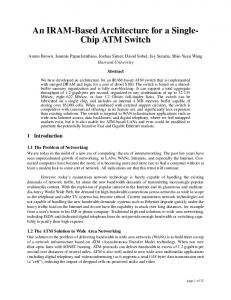
System Architecture In addition to adjust the compatibility between equipment, transfer protocols and data formats, the ATM technology has capability to identify and address an elevated number of remote data acquisition and control units. While the adaptation of data formats and protocols can be implemented, at the ATM Adaptation Layer (AAL) using, for instance, AAL Type 3/4 [2]; the identification and the address, of each involved unit, can be easily done through the ATM Layer Virtual Path or Virtual Channel Identifiers (VPI/VCI) [3] of switched or semi-permanent connections between units. The hole system can be easily implemented with the fowling components: Remote ATM interface units; central processing units; Wired, Optical or RF Links operating at 2 Mbit/s; ATM terminals incorporating data control and management applications. ATM Interface Unit ATM interface units are needed to adapt the information flow and the transmission protocols between non-ATM terminals and the ATM network. As it is shown in figure 1, this unit, called Remote Unit, carries out the following functions: adaptation of the information flow generated or destined to remote terminals trough the Utopia Bus [4]; processing the headers of ATM Adaptation Layer (AAL) and the ATM Layer; handling transceiver, framing and Operation and Maintenance (OAM) procedures [5]; control of hardware devices, namely the arbitration of the redundant transceivers, incorporated within line interface boards. Central Processing Unit One or more remote units can be connected to a central unit, trough a 2 MBit/s link. Since the information flow generated or destined to remote units is usually very low bit rate, the central unit can concentrate and distribute the traffic, of a large number of remote unit, over another 2 MBit/s link or over an Ethernet port.
Remote Unit Line Interface Controller
Frame G. 703
AAL 3/4 ATM Cell Processor
Arbiter Utopia Data Bus
boards1 , two distinct reference configurations can be advised for interconnection topology: Add and Drop Wired Ring; and Wireless Clusters. ADD and Drop Wired Ring As its is shown on figure 3, an Add and Drop Wired Ring can be used to connect each remote unit to the central unit. For safety reasons, the transmission system can be duplicated, forming two bi-directional rings and allowing that, in case of break of one connection, destination units can be reached by sending the information in the opposite direction.
Figure 1: - Remote Unit Block Diagram. More than handling with deterministic or statistical multiplexing and demultiplexing of remote unit's traffic, the central unit is also able to execute interworking functionalities between ATM and Ethernet protocols, namely LAN Emulation and Classical IP over ATM. Figure 2 presents the block diagram of the Central Unit. There are two data buses: the Utopia Bus sustains the cell transfer between Line Interface boards; while the processor bus permits that ATM cells and IP Packets can be transferred between the processor, the arbitration controller and the memory. The central unit also carries out the Operation and Maintenance (OAM) procedures, as well as, the arbitrationÕs control of the (redundant) line interlaces boards.
ISDN Ethernet
Central Unit
G. 703
Remote Unit
Remote Unit
Figure 3: - ADD and Drop Wired Ring Data Acquisition System.
It has been considered two scenarios for wired transmission between the Remote Units and the Central Unit:
Central Unit Processor Bus Memory
Remote Unit
1 - The wired add and drop ring operates at 2 MBit/s, according ITU-T recommendations G. 703[6] and G.804[7].
Arbitration Controller
Processor
G. 703
LANE
Line Interface
IP/ATM
Line Interface
G. 703
Utopia Bus Ethernet Figure 2: - Central Unit Block Diagram Network Configurations Several remote units can be connected with one or more central units over a wired or wireless transmission system. Since each remote or central unit has two bi-directional transceivers on its interface
2 - The wired add and drop ring operates at 2 MBit/s, supporting directly the ATM cells, without G.703 frame. Wireless Clusters If remote units are located far way from each other, or from the central unit, a wireless transmission system may be necessary to interconnect themselves. Figure 4 illustrates that scenario, within which, several remote units are clustering over bi-directional RF connections, with a central unit.
1
In addition, theses transceivers can be configurable to perform redundant (duplicated) point to point or bidirectional add and drop transmission ports.
RF
Central Unit ISDN Ethernet
RF
Remote Unit
Central and Remote Units
Remote Unit
Central and Remote Units
Central and Remote Units
RF ISDN or ATM Network
Remote Unit Figure 4: - Wireless Data Acquisition System.
Control System
The transmission control of the downstream flow is different from the upstream flow. The Central Unit can broadcast the downstream information flow, since each remote unit is able to recognize its own traffic, trough the VPI and the VCI of the ATM cells. While the upstream information flow need be synchronized on a time slot basis by remote units, in order to avoid collisions. Other standardized techniques, such Time Division Multi Access (TDMA) and Code Division Multi Access (CDMA), can also be used. Flexible Configuration One or more clusters assembled a central unit and several remote units can be interconnected to another central unit or to a centralized or distributed acquisition and control systems, over a standardized communications network. As its is shown on figure 5, Ethernet, ISDN and ATM networks are qualified support interconnections between remote units or between remote units and control systems.
Central and Remote Units
Central Unit
Central and Remote Units
Central and Remote Units
Figure 5: - Reference configurations for interconnecting system clusters over local or public communication networks. Since the proposed system is presently under development, the throughput evaluation on real applications is not yet done. However, throughput capacity and other quality of service parameters, could be estimated for hypothetical and realistic reference scenarios.
Throughput Evaluation
Bit Rate
The main capabilities of the proposed architecture can be summarized as the following.
As is has been previously referred, ATM cells can either be transmitted directly over the link with no frame, or mapped within a frame, in conformity with the ITU-T G.804 [7], and transmitted over 2 Mbit/s links, according G.703 [6]. Table 1 presents, for both scenarios, the expected maximum throughput capacity available for each remote unit, when several units share the connection ring, as it is shown in figure 3. It is supposed that an ATM Terminal, incorporating a data management application (e.g. control system), is connected over a wired 2 Mbit/s link (E1) to the central unit. In addiction, the data control application, enclosed one the central unit (concentrator /distributor), generates one OAM cell for each 26 information cell2 .
* Negotiation of the resource allocation, according to the traffic characteristics; * Easily addressing of each terminal equipment, using their own switched or semi-permanent virtual channel or path identifiers; * Interconnection of the involved remote equipment over Wired, Optical or RF transmission systems; * Interconnection of several remote units or clusters over standardized communications networks; * Guarantying of the quality of service; * Supporting ATM applications to process remotely the information and control data; * Supporting management and remote configuration of the involved equipment; * Supporting interconnection with other non A T M transmission systems, like Ethernet or ISDN;
2
This proportion is equivalent to ratio of idle cells on the Broadband User Network Interface [8].
2 Mbit/s Links Number of Remote Units 1 5 10 50 100
Throughput Capacity
(KBit / s) ATM Wire Ring 1637.2 327.5 163.7 32.7 16.4
ATM over G.703 1534.9 306.9 153.5 30.7 15.3
Table 1: - Maximum throughput capacity of each remote unit connected to the central at 2 MBit/s. The figures show that tens of remote units can be connected to central units at bit rates on the order of tens of Kbit/s, which is suitable for real time data acquisition and control applications. The figures also show that, if the G.703 frame is used, the throughput capacity available, for each unit, is 93% less than if the ATM cells are transmitted without frame. If wireless transmission is used, the figures of table 1 can be applicable only to the downstream flow. For the upstream flow, the silence time between TDMA bursts and CDMA overhead have not yet been measured. Delay The end-to-end transmission delay is very dependent of the transmission configuration used. Naturally, the add and drop wired ring presents higher delays than the wireless transmission, because at each hop the ATM cells have to assembled and reassembled. On wireless transmission, the delay introduced on the upstream flow can also be higher than on the downstream, namely if it occurs collisions between remote units. Delay Variation Some transmission systems, such as, the Ethernet and RF, depending of the traffic loud, can introduce variations on end-to-end delays. As it is known, if more than one transmission request occurs at the same time, or if cells retransmit has been inevitable due to transmission errors, the delay increases. Moreover, if the system is weighty loud (e.g., high number of remote units, overtaking altogether the transmission capacity), the variation of the processing time of the interworking functions can, as well, increases the delay variation.
Conclusions A Modular Architecture for High Flexibility ATM Based Control System has been proposed. This system incorporates equipment and applications, which can be integrated and configured to be adapted to different traffic environments. As a communication infrastructure, the proposed system is able to connect several remote units through a central unit over wired or wireless links. The communication system can also be interconnected, over a switched telecommunications network, to link different data acquisition and actuator units, which can be located over a wide area, for instance, on sparse industrial or agricultural plants.
References [1] ITU-T, ÒB-ISDN Protocol Reference Model and its ApplicationÓ, Rec. I.321, ITU, Geneva, 1991. [2] ITU-T, ÒB-ISDN ATM Adaptation Layer (AAL) specification: Type 3/4Ó, Rec. I.363.3, ITU, Geneva, 1996. [3] ITU-T, ÒB-ISDN ATM Layer SpecificationÓ, Rec. I.361, ITU, Geneva, 1995. [4] h t t p : / / w w w . a t m f o r u m . c o m / a t m forum/specs/approved.html [5] ITU-T, ÒB-ISDN Operation and Maintenance principles and functionsÓ, Rec. I.610, ITU, Geneva, 1995. [6]CCITT, General Aspects of Digital Transmission Systems; Terminal EquipementsÓ, Blue Book - Rec. G.700 - G.772, Vol. III-4. CCITT, Geneva, 1989. [7] ITU-T, ÒATM cell mapping into plesiochronous digital hierarchy (PDH)Ó, Rec. G.804, ITU, Geneva, 1998 [8] ITU-T, ÒB-ISDN User-Network InterfaceÓ, Rec. I.413, ITU, Geneva, March 1993.