This new architecture uses small, dedicated ... server. Figure 4 - A query respond with heartbeat setup. To support this method of exchange, three messages are.
Modular Scalable Architecture for the Navigation of the ATLAS Autonomous Robots M. Oliveira, P. Stein, J. Almeida, V. Santos {mriem, procopio, almeida.j, vitor}@ua.pt Department of Mechanical Engineering, TEMA - University of Aveiro 3810 Aveiro Portugal Abstract — This paper describes a solution to integrate disparate devices, both for perception and actuation, distributed amid distinct processing entities. Although the philosophy may be applied to many systems and machines, emphasis will be made on autonomous mobile robots’ perception, actuation and intercommunication abilities. The solution uses inter-process communication (IPC) and encapsulation of messages in standard forms in the same trend as the CARMEN framework, where inspiration was gotten from. The modular architecture derived thereof allows to continuously increase the system complexity without changing whatever was previously implemented. Besides this scalable nature, the resulting architecture represents a unified approach that makes it hardware-independent where each machine simply relies on small specific modules. The IPC and CARMEN insights have been successfully adapted to two different robots within only one development project. The implementation will focus particularly on image efficient transfer among processes for real-time autonomous navigation.
drawbacks, and how the new proposed architecture overcomes them. Following that, different techniques of information exchange between modules are discussed, emphasizing the development of a new technique to overcome IPC transfer limitations. Finally, the currently developed modules and message structures are presented, followed by the conclusion and future steps.
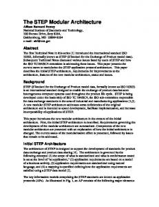
Figure 1 – Atlas 2008 (left) and the Atlas MV (right) robots.
I. INTRODUCTION
II. HARDWARE INVOLVED
robots tend to become more and more complex both in hardware and software when the challenges raise and performance is paramount. The increasing affordability of more advanced sensors and devices induces researchers to include them on their mobile robots for more robust perception and navigation abilities. However, and due also to the disparity of standards and protocols, adding up off-the-shelf equipment along with custom designed boards or devices is not always a straightforward task. Moreover, keeping the pace in software development when there are changes in the team of programmers is often a nuisance for project managers. To address these problems, the CARMEN (Carnegie Mellon Robot Navigation Toolkit) framework [1] appears as a tempting choice. It is a collection of modular software for mobile robots, and provides several useful functions for development of new modules and also for information exchanging amongst them. The communication between modules relies on the Inter Process Communication (IPC), developed by Reid Simmons [2] to be a flexible and efficient message exchanger; the potentialities of this IPC system are well assessed by its usage in paradigmatic projects related to NASA or the well known DARPA Challenge [6] [7] [8]. This work details the experience of adapting this new architecture in two competitions robots, named ATLAS MV and ATLAS 2008 [3], shown in Figure 1. In the remainder of the paper, the next chapter will detail the installed hardware in both ATLAS robots. Chapter III describes the previous installed software architecture, its
Both ATLAS robots have similar basic hardware interface like cameras, traction motor, steer motor and digital input/output. The ATLAS-MV, which is a redesign of its ancestor ATLAS-2008, also incorporates some innovative hardware. One of them is a Pan and Tilt Unit (PTU) that it is used to change the cameras orientation providing active perception capabilities. The system also accounts for a Laser Range Finder with an accuracy of a few centimeters and a range of up to 30 meters. The cameras are connected with the computer using a FireWire (IEEE 1394) interface and Direct Memory Access (DMA), which allow them to read or write to memory independently of the main computer processor. The ATLAS 2008 uses two cameras for navigation plus one for traffic lights recognition, while the new ATLAS MV uses four cameras mounted atop the PTU, and are employed in several tasks involving navigation and obstacles recognition. For the interface with the traction and steer motors, a microcontroller is used and connects to the computer using a RS232 link. The digital input/outputs are also interfaced using a microcontroller and a RS232 connection to the computer. The digital outputs are responsible for the brake and lights activation. Digital inputs, in other hand, receive readings from digital auxiliary sensors. This microcontroller board is projected in a way that it can easily incorporate more and distinct sensors. Both the PTU and the Laser Range Finder have their own controllers incorporated and are connected to the computer using an USB port.
A
UTONOMOUS
The previous software architecture installed on the robots has achieved successful results, but the code was based on a single large loop that would go through all hardware inputs/outputs sequentially, changing variable states that would affect the chosen behavior for the robot. This conveys a series of problems since small changes affect the whole code and pose difficulties in interfacing with new hardware. As the program was sequential, important events could be missed if the processor was taking too long to complete the loop, and if a “bug” or a deadlock happened, the whole program could hang. To overcome these limitations, a modular architecture based on the CARMEN toolkit [1] has been devised. The idea is to split the old code into several modules, where each part is responsible for a small number of tasks. Information is exchanged between modules using standard messages, so new processing techniques or hardware could be easily incorporated. The new system architecture relies on separate modules, i.e., computer processes that run in parallel. These modules were divided from the previous architecture bearing in mind that each would contain a simple task. Each module processes the information received and outputs the result. Hence, the way information must travel from one module to the other is a critical issue. Communicating with the sensors often requires constant monitoring by the process running on the computer. This new architecture uses small, dedicated modules that handle hardware and communicate with other parallel modules via IPC. The modular architecture is also more robust, because redundant parallel modules may compensate fails of others. Also, because the IPC [2] based communication is performed through TCP/IP connections, messages can be easily exchanged between processes running in different machines. Hence, the entire program may be distributed in several computers, increasing the computational power of the robots, if so required. This is usually an important issue when running real time vision-based algorithms. IV. INFORMATION EXCHANGE The information exchanged among modules must be classified so that a module receives only what it actually requires, and not everything else. This is accomplished by encapsulating information into messages. A module interested in some particular information can then ask to receive a specific message. On the other hand, a module that produces some specific output can constantly send a message containing a certain type of information. A. Publish/Subscribe Method Message exchanging can be done in several ways. The simplest method is called publish/subscribe (Figure 2). Publisher Module
message type A
Subscriber Module
Figure 2 – A simple publish subscribe setup.
In
this scenario,
a publisher module generates
information that is packed into a message of a given type, let’s say, “A”. Every other module interested in the information contained in message type “A” should subscribe to it. When that information is available, the publisher module publishes a message type “A” that will be redirected by IPC to all modules that have previously subscribed to it. One disadvantage is that the publisher module requires that the subscribing module accepts all messages of type “A”, even if it does not require them all. This may become critical if the publisher’s cycle time is shorter than the one of the subscriber. Figure 3 shows a message exchange where this phenomenon takes place. preparing data
waiting new message
message publication preparing data
Time
III. PREVIOUS VS NEW ARCHITECTURE
message handling
message publication preparing data
processing
message publication preparing data message publication
waiting new message
Figure 3 – An example of a time sequence (vertical axis) of a publish/subscribe message exchange. The publishing module (left) has a faster cycle time (represented by brackets) than the subscriber module (right). Because of this, the subscriber module receives 2 messages while still processing the first one.
In this case, there is going to be a growing queue of messages that, at some point, will overflow and cause the IPC central module to crash, as observed in practice, especially for large messages (hundreds of kilobytes). Because of this, the publish/subscribe message exchange methodology should be considered only if the subscriber module is faster than the publisher, or if the handling of the message reception performed by the subscriber is a very fast routine. For this reason, it is not advisable to send large messages containing images or laser scans using this specific methodology. B. Query/Respond As stated, the publish/subscribe method is appropriate for exchanging small messages or for fast processing modules. However, as seen in chapter II, the robots have several cameras/lasers onboard. Cameras installed on ATLAS robots usually produce 320×240, 3 channels RGB images at a rate of about 30 FPS. This means that a module performing image acquisition generates approximately 7 Megabytes of information every second (320 × 240 pixels × 3 channels × 30 FPS ≈ 7 MB). Publishing such a large amount of information caused IPC to overload during our
tests. This occurred especially when the subscriber module was not able to handle the information flow. Furthermore, if the subscriber modules cannot process the information fast enough, the messages are sent but not processed. These limitations can be circumvented using a second methodology available in IPC: the module that can send the information, called in this case the server module, does so only when asked by the receiving module, here called the query module. Message exchange rate is set by the query module, instead of being arbitrarily defined by the server. heartbeat Server Module
query
Query Module
response
Figure 4 - A query respond with heartbeat setup.
To support this method of exchange, three messages are defined: the heartbeat, the query and the response messages (Figure 4). The heartbeat message indicates that the server has new information available and is able to send it; it is a small message, a mere notification to whoever is interested in the new information generated that a new one is available. Because of this, heartbeat messages are broadcasted by the server module, using the publish/subscribe technique, thus allowing several modules to be informed. The image acquisition module would publish thirty heartbeat messages every second. preparing data heartbeat publication
Time
query waiting
other processing
preparing data
responding to query
C. Shared Memory Query/Respond Method The disadvantage of the query/respond method is that because messages are queried by a specific module, the server responds only to this one, i.e. it is a peer to peer communication. If the server module is meant to send large amounts of information to several query modules, the message traffic would increase as many times as the number of receiving modules. In the worst case scenario, if the number of query modules is large enough, the server module may not be able to respond to them all in the time allocated to listen to the queries. To solve this problem, a new method has been devised, where the server module writes the message containing the response to a shared memory address. This technique takes advantages of IPC marshal/unmarshal functionalities. Marshaling is the process of transforming the message into a configurable easily reversible linear byte array. Messages are defined as C language structures, but before being sent must previously be transformed, i.e., marshaled, into byte arrays. To be marshaled, the format of the message structure is first defined. Figure 6 shows an example of a message. typedef struct { int var1; char var2; int var3[2]; }type_msgA;
heartbeat publication query waiting
query module waits for the response. The response message can be large (could contain an image, for example), and is sent by the server to the query module only in reply to a query. The response is also peer to peer. Though more complex, this setup is particularly useful for transmitting large messages since that transmission only occurs when the query module actually needs the information, reducing the message traffic. If the query module is faster than the server module, heartbeat messages ensure that no query is done unless new information is available on the server’s side. The flow of messages is shown in Figure 5. Heartbeat and queries are control messages that synchronize both modules so the information is exchanged only when actually needed. In this case, the complexity increase is compensated by avoiding sending unneeded large messages. Because of this, this setup should only be employed when the messages to be exchanged are large.
#define msgA_format “{int, char, }”
query waiting response handling response
Figure 5 – A query response time flow. Heartbeat messages (dotted line) are published whenever the server module (on the left) generates new information. The query module (on the right) queries the information (dashed line) only when it actually requires it.
The query message is also a small one, and is sent by the query module to the server in a peer to peer communication. After sending the query message, the
Figure 6 - An example data structure in C and its format definition. This could be a message to be exchanged between processes.
In the case of Figure 6, marshaling would take the format of the structure (msgA_format) as one integer followed by a char followed by an array of 2 integers. The modules use IPC to marshal every message structure when sending, and to unmarshal when receiving. In this particular information exchange setup, the server module allocates a shared memory segment with the size of the message, and then stores the message directly onto the shared memory. After this operation, a heartbeat message is published indicating that new information is available.
The query module attaches itself to the memory segment and unmarshals the information to a variable of type type_msgA. The attach operation requires the shared memory address (Figure 7). For this purpose a new message is defined containing shared memory information, its address and size. This message is queried to the server during the query module’s initialization procedures. Afterwards, whenever a heartbeat is received, the query module just unmarshals the information from the shared memory and gets a copy of the message.
Time
other processing listen shared memory query
query shared memory information
shared memory info respond
waiting response
A. Cameras acquisition module The cameras acquisition module (Figure 8) is intended to acquire images from the Firewire cameras installed on the robots. All message exchange methodologies have been developed: publish/subscribe query/response and shared memory.
Figure 8 – The cameras acquisition module.
other processing marshal to shared memory
In this paper, only the first category of hardware communication modules will be described.
other processing
The published messages have the format of Figure 9. typedef struct { int width; int height; int bytes_per_pixel; int image_size; char *image; double timestamp; char *host; } lar_ubcamera_image_message;
/*width in pixels*/ /*height in pixels*/ /* 3 (RGB) */ /*w*h*3*/ /*pointer to image data*/ /*timestamp of message*/ /*used by IPC*/
Figure 9 – The image message format structure.
heartbeat publication unmarshal from shared memory Figure 7 – A query response time flow using shared memory. The query module (on the right) queries for the shared memory id (dashed arrow). The server module (on the left) responds with the information (dotted arrow). The query process then attaches itself to the shared memory and unmarshals the data whenever a heartbeat is received.
A limitation of this method is that, because it is not based on TCP/IP, it does not work when the processes run on separate machines. Another glitch is that on large messages, there is some possibility that the query module may be still reading part of the message while the server is writing. This may lead to reading messages that are actually a combination of two different messages. In our particular case, this is not an issue, although if required, it could nevertheless be prevented by using semaphores. The bottom line is that the method is very fast and addresses the problems discussed deriving from the usage of multiple query modules. V. PROPOSED MODULES FOR ATLAS Several modules have been developed in the process of migration from the old architecture to the new, modular one. The modules can be roughly divided into three categories: hardware interface, features extractors and planning/decision. The first is responsible for every interaction with the hardware: data acquisition and motors command. The feature extractors will process the acquired data, where each module is responsible for one type of feature such as obstacle or lane detection. The last category is dedicated to the reasoning capabilities of the robots. It makes use of all the detected features and, based on the context, will decide and plan the robot’s behavior.
This module also enables the real time setting of the cameras parameters. Brightness, saturation, white balance, shutter and others can be set to a particular value. The module is also capable of handing out distortion corrected images taken from wide angle lens cameras, if a prior chessboard calibration has been performed. B. Laser acquisition module The laser acquisition module (Figure 10) acquires laser data from the laser and sends the information to other modules.
Figure 10 – The laser acquisition module.
The message structure of the laser module is shown in Figure 11. Several laser parameters can be set at startup: angular resolution, start/end scan angle, among others. typedef struct { carmen_laser_laser_type_t laser_type; /*laser model*/ double start_angle; /*angle of the first beam*/ double fov; /*field of view of the laser*/ double angular_resolution; /*up to 0.25*/ double maximum_range; /*30 meters*/ double accuracy; /*0.1 meters*/ carmen_laser_remission_type_t remission_mode; /*not used*/ } lar_laser_laser_config_t; typedef struct { int id; /*laser id*/ carmen_laser_laser_config_t config; /*above*/ int num_readings; /*number of range values sent*/ float *range; /*laser range values*/ int num_remissions; /*number of remission values*/ float *remission; /*remission laser values*/ double timestamp; /*timestamp of message*/ char *host; /*used by IPC*/ } lar_laser_laser_message;
Figure 11 – The laser message format. Structure proposed by CARMEN.
It is also possible to use any one of the three methods described in chapter IV to exchange the laser messages. C. PTU module The PTU module (Figure 12) is capable of commanding the pan and tilt unit based on orders received from other modules. It can also inform other modules of the pan and tilt state, i.e., axis position, speed and acceleration.
The Robot base module receives the message lar_atlas_dir_and_speed_message (Figure 16), and translates that information to the specific robot hardware. In this way, different robots will have different base modules, but will be able to receive the same command messages. This module also publishes a message containing information about the robot current speed, steer angle, lights state and digital inputs readings, by means of a lar_atlas_status_message. typedef struct { double dir; int speed; double timestamp; char *host; }lar_atlas_dir_and_speed_message;
/*steer direction*/ /*speed*/ /*timestamp of message*/ /*used by IPC*/
Figure 16 – Definition of the message for commanding the base. Figure 12 – The PTU control module.
Because the messages related to the PTU control/monitoring are small, only the publish/subscribe method has been implemented. If a module requires information on the state of PTU it subscribes to messages of type lar_ptu_status_message, defined in Figure 13. typedef struct {double pan;double tilt;}TYPE_pantil; typedef struct { char *dev; /*serial port device*/ int devnum; /*serial port device number*/ int baudrate; /*communications baurate*/ struct { TYPE_pantil position; /*in radians*/ TYPE_pantil speed; /*in radians per sec*/ }current; /*current position and speed*/ struct { TYPE_pantil position; /*in radians*/ TYPE_pantil speed; /*in radians per sec*/ }desired; /*desired position and speed*/ typedef struct{ char purevelocity; /*is pure velocity set*/ char imediatepositionexecution; /*IPE flag*/ }flg; /*ptu state flags*/ double timestamp; /*timestamp of message*/ char *host; /*used by IPC*/ }lar_ptu_status_message;
Figure 13 – The message format to get information on the PTU’s state.
If, on the other hand, a module wishes to command the PTU positioning or speed, it should publish a message of the type lar_ptu_command_message (Figure 14). During startup, the PTU control module subscribes to this message type. It is actually possible to have different modules competing for the PTU’s command sending the same message type. The PTU module will just receive all the messages and execute them sequentially. typedef struct { TYPE_pantil position; TYPE_pantil speed; int usepurevelocity; double timestamp; char *host; }lar_ptu_command_message;
/*ordered position*/ /*ordered speed*/ /*use pure velocity*/ /*timestamp of message*/ /*used by IPC*/
E. Teleoperation module This module allows the remote command of the hardware related features of the robot using a standard gamepad. It does not have any specific publication/subscription routines. Instead, it simply makes use of the routines implemented by each of the modules it wants to control.
Figure 17 - Definition of the message for commanding the base.
It has two distinct operation modes: a command mode and a tutorial mode. In the first, it can command the speed, steering, lights and the PTU unit, publishing a lar_atlas_dir_and_speed_message (Figure 16) and a ptu_command_message (Figure 14). In tutorial mode, pressing the buttons or axes provides an audio tutorial. This is accomplished by instructing the sound player module to reproduce the audio that matches to the button pressed. F. Sound Player module The Sound Player module (Figure 18) is capable of generating audio output. For synchronization purposes, it can also inform other modules if it is busy playing a sound.
Figure 14 – The message format used to give orders to the PTU module.
D. Robot Base module This module is responsible for interfacing with the traction and steer motors. Also digital input readings and digital output commands are performed here (Figure 15).
Figure 15 – The base module.
Figure 18 – Sound player Module.
Any module can require a sound message to be played by publishing a lar_soundplayer_message. This message is defined in Figure 19, with the identification of the media to be played, given as a file name (string) or as a numeric identification. typedef struct { int filenumber; char *filename; int mode; double timestamp; char *host; }lar_soundplayer_message;
/*numeric id*/ /*file name to be played*/ /*mode (id by number or by name)*/ /*timestamp of image*/ /*used by IPC*/
Figure 19 - Definition of the message for commanding the sound player.
Upon receiving the command, the sound player makes use of Libao library [5] functions to reproduce it. The sound player module indicates its status (busy or available) by publishing a lar_soundplayer_status_message, defined in Figure 20. This module allows improved user/robot interactivity and also provides debug facilities. typedef struct { int status; /*Status of the sound generator*/ double timestamp; /*timestamp of image*/ char *host; /*used by IPC*/ }lar_soundplayer_status_message;
Figure 20 – The message format to get the status of the sound player.
G. Sensor Fusion Module The sensor fusion module (Figure 21) is the responsible for merging the information coming from the cameras and the laser sensors installed on the robots. It creates a common reference representation of the measurements taken, whether they are images or range scans. Because cameras are mounted on the PTU, cameras’ positions are a function of the PTU orientation.
Figure 21 – The sensor fusion module’s input and output messages.
The module can fuse several images captured from multiple cameras along with laser information, generating enhanced images of the road, in a birdview perspective. This algorithm is described in detail in [4]. Figure 22 shows a birdview of the road obtained by merging the images of two different cameras.
the specific sensorial setup of a given robot, it is reshaped into a common reference. The advantage here is that subsequent modules (like feature extractors, road detectors, obstacle detectors, etc) can rely on a constant, predefined representation of the data and so may work without need for reconfiguration, regardless of the current sensorial setup, regardless of the robot. VI. CONCLUSIONS AND FINAL REMARKS The paper described a successful adaptation of the CMU CARMEN and IPC approaches to two distinct autonomous robots. The resulting architecture has proven fully scalable since any modules can be added or suppressed without compromising the global operability. The encapsulation of information in predefined messages, by dividing the code in small task oriented modules and experimenting different forms of information exchange, has been a central issue. The IPC framework available at the CARMEN community proved reliable except for some limitations regarding the transmission of large data sets at a high frequency. This was overcome with the development of a mixed method that involved the well known shared memory intercommunication together with IPC structures and functions, resulting in a seamless integration with the already developed modules, and can be seen as an extension of them. The modules presented are all hardware-related (with exception of the Sensor Fusion Module, which is a preprocessing module), as this was the first step in the effort of migrating to the new architecture, and as so it had to be carefully planned to serve as the foundation for the further development of higher level modules as the features extractors and decision/planning modules. A final important outcome of this work is the strongly organized software and functional architecture on the ATLAS robots, allowing an unlimited team of developers to cooperate together. This was indeed the major breakthrough, and represents a significant step towards more demanding projects on complex perception and autonomous navigation of advanced machines. VII. REFERENCES [1] [2]
Figure 22 – The images taken from the left and right camera and the birdview of the road obtained by merging both images.
[3]
During initialization, this module reads some parameters that define a box of interest. This rectangular region, viewed in Figure 22, is the area where the robot is interested on receiving sensory data. If, for some reason, one particular sensor harvests information of an uninteresting area for the robot, i.e., an area outside the box of interest, this module ensures that this information, being regarded as unimportant, is clipped away from the merged information. The ultimate goal of this task is to find a common representation for a multitude of sensor types and/or configurations. This ensures that, no matter
[4]
[5] [6] [7] [8]
CARMEN, Carnegie Mellon Navigation Toolkit, found at http://carmen.sourceforge.net/ on February 2009. R. Simmons, and D. Apfelbaum, “ A task description language for robot control”. In 1998 Proceedings of the Conference on Intelligent Robots and Systems (IROS), Victoria, CA. M. Oliveira, V. Santos, A Vision-based Solution for the Navigation of a Mobile Robot in a Road-like Environment, Robótica, nº69, 2007 p.8 (ISSN: 0874-9019) Oliveira M., Santos V., Multi-Camera Active Perception System with Variable Image Perspective for Mobile Robot Navigation, 8th Conference on Mobile Robots and Competitions, Portuguese Robotics Open, Aveiro, April 2008. Libao, Open Source Audio Output Library, found at http://www.xiph.org/ao/ on January 2009. DARPA Grand Challenge, http://www.darpa.mil/grandchallenge/, February 2009. M. Montemerlo, et al., “Junior: The Stanford entry in the Urban Challenge,” Journal of Field Robotics, vol. 25, 2008, pp. 569-597. C. Urmson, et al., “Autonomous driving in urban environments: Boss and the Urban Challenge,” Journal of Field Robotics, vol. 25, 2008, pp. 425-466.