Jun 2, 1999 - in machine logic, process automation and manufactur- ing. They were ... tional Standard IEC 61131-3 for PLC programming. (IEC, 1993) was ...
To appear in: Proceedings of Joint 24th IFAC/IFIP Workshop on Real-Time Programming and The Third International Workshop on Active and Real-Time Database Systems, Schloß Dagstuhl, Germany, May 30th - June 2nd, 1999.
MODULAR VERIFICATION OF FUNCTION BLOCK BASED INDUSTRIAL CONTROL SYSTEMS Norbert V¨olker and Bernd J. Kr¨amer University of Essex, United Kingdom FernUniversit¨at, Hagen, Germany
Abstract: IEC 61131-3, the world-wide standard for industrial control programming, is increasingly being used in safety-related control applications. Control loops are built from components taken from domain-specific function block libraries. Code inspection and testing are the two predominant quality assurance techniques. For highly dependable control applications, however, these techniques are not sufficient, in general. This paper suggests to augment testing with compositional, theorem-prover supported verification. The approach is based on a representation of IEC 61131-3 function blocks in higher-order logic. The verification task is separated into the a priori verification of library components and a separate proof of individual application programs. Keywords: Safety-critical control systems, dependable software, PLC programming, IEC 61131-3, modular verification, higher order logic theorem proving.
1. INTRODUCTION Programmable logic controllers (PLCs) form a growing market of special purpose hybrid systems integrating micro-electronic and software components. PLCs are particularly suited to solve application problems in machine logic, process automation and manufacturing. They were developed to replace traditional hardwired switching networks based on relay or discrete electronic logic. The rapid development of PLC systems in the 1980’s led to a wealth of incompatible vendor-specific PLC programming languages within the process industries impeding the design of more complex, open and distributed control applications. In response, the International Standard IEC 61131-3 for PLC programming (IEC, 1993) was developed. This standard applies to a wide range of programmable controllers and harmonizes the way engineers look at industrial control. The standard provides a class of five languages that overlap conceptually and share a subset of programming elements. Three languages of the standard, Function Block Diagram (FBD), Ladder Diagram (LD) and Sequential Function Chart (SFC) have
a graphical appearance. FBD supports componentbased application programming while SFC is mainly used for describing sequential behavior of a control system including alternative and parallel execution sequences. New capabilities of PLCs, the comfort of the PLC languages, and strong economical demands led to the current situation of increased dependence on PLCbased systems for control and automation functions in safety-related applications. Examples include traffic control, patient monitoring, chemical process automation and emergency shut down systems in power generation. The growing social awareness of a need to protect the environment, a higher sensitivity to accidents caused by ill-designed technology or processes, and a declining confidence in marketing statements of manufacturers lead to enormous pressure to increase the dependability of safety related applications. In practice however, there is a lack of rigorous proof techniques and robust tools which can be used effectively by practitioners in industry and regulatory authorities. Existing design guidelines and testing practices help to detect design and programming errors but they can-
not guarantee the absence of faults because exhaustive testing is limited to rare cases. The main body of this paper explores function blocks – which represent the engineer’s idea of re-usable ”software ICs” – and sequential function charts in order to develop a modular, theorem prover-based verification framework. By taking components from application-specific libraries of verified standard function blocks, the verification of new applications is simplified considerably because only the correctness of the composition has to be established for each new application. In the following section, the core concepts of FBD and SFC are introduced. In Section 3, the underlying higher order logic is discussed. The verification approach is based on a semantic embedding of the selected PLC languages in that logic. This embedding is explained in Section 4, while the verification process and the challenges of handling complex continuous systems are sketched in Section 5 and 6. The paper concludes with a brief summary and an outlook on an industrial strength verification tool which can ultimately be used by domain experts with little or no expertise in software verification.
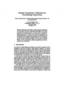
2. FUNCTION BLOCKS AND SEQUENTIAL FUNCTION CHARTS Function blocks are program organization units with a private state that persists from one invocation to the next. A function block interacts with its environment primarily via input and output variables. The standard also allows global variables but the verification framework does not support these. Besides keeping the semantics simple, this also has the advantage that the execution of function blocks has no side-effects. From a semantic point of view, function blocks are a special case of deterministic reactive modules (Alur and Henzinger, 1996). Their execution takes place in a sequence of rounds. At the start of each round, the input variables are read. This is followed by an update of the private and output variables. This update is functionally dependent on the current value of the input variables and the previous state of the private and output variables. The description of a function block can be split into the declaration of its external interface and a specification of the internal implementation. The former is part of the function block signature that specifies the types and names of variables including local instances of function blocks. In the context of graphical representations, the input and output variables are also referred to as ports. The internal implementation of a function block body can be carried out in any of the five IEC 61131-3 programming languages or even in another language such as C or Java.
DEBOUNCE BOOL
IN
TIME
DB_TIME
OUT
BOOL
ET_OFF
TIME
(a) External interface
IN
DB_ON TON IN Q
111 000
PT ET
DB_FF SR S R
Q
OUT
DB_OFF TON DB_TIME
0011 1100
IN Q PT ET
ET_OFF
(b) Implementation as function block diagram
Fig. 1. Function block DEBOUNCE DB_ON (IN := IN, PT := DB_TIME); DB_OFF (IN := NOT IN, PT:= DB_TIME) DB_FF (S := DB_ON.Q, R := DB_OFF.Q); OUT := DB_FF.Q; ET_OFF := DB_OFF.ET;
Fig. 2. DEBOUNCE in Structured Text As an example, Figure 1(a) shows a graphical representation of the external interface of the function block DEBOUNCE taken from the IEC 61131-3. DEBOUNCE has two input variables IN and DB TIME of type BOOL and TIME and two output variables OUT and ET OFF of the same types. An implementation of DEBOUNCE as a function block diagram is depicted in Figure 1(b). The function blocks DB ON and DB OFF are two separate instances of the timer function block TON while DB FF is an instance of the standard SR flip-flop. By connecting input and output ports, a diagram is “wired together” from the components. As in the graphical representation of circuits, the open circle at input port IN of DB OFF indicates signal negation. The named instances of function blocks will usually also be referred to as function blocks. The function block DEBOUNCE is composed from standard function blocks predefined in the norm. Such a composite function block can itself be used in further applications just as if it was one of the standard function blocks. This feature is useful for building an in-house or domain specific collection of function blocks. The textual IEC 61131-3 language ST is similar in appearance to a structured programming language such as PASCAL. Figure 2 shows an alternative implementation of the body of DEBOUNCE in ST.
The second graphical language of the standard, SFC, can be regarded as an application of Petri nets. Its language concepts include transitions, steps and actions. They serve to co-ordinate the execution of function blocks that are regarded as asynchronous sequential processes. The role of SFC is illustrated by a small laboratory plant application. This has been used previously as a benchmark for the tool-aided analysis of discretely controlled continuous systems (Kowalewski et al., 1997). The plant features two cylindrical tanks that are located at different levels (see Fig. 2). The tanks are equipped with three pipes and three valves V0 , V1 and V2 which control the flow of liquid between the tanks, at the inlet and the outlet. The liquid level in the second tank is measured by a sensor L. A core safety requirement for this application is to avoid overflow in the coupled tank system. V0
V1
L V2
Fig. 3. Laboratory plant The SFC depicted in Fig 2 controls the behavior of the system. It consists of five steps s0, .., s4. The actions connected with the steps control the state of the valves: the qualifiers S and R denote setting and resetting of an action, respectively. The transitions separating the steps are enabled by Boolean valued expressions representing conditions on the state of the function block. The encapsulation provided by function blocks together with their flexibility with respect to the internal implementation furthers their reuse in different appliS0 Start S1
S V0 Step_1.T >= T1
S2
S V1 Step_2.T >= T2
S3
S V2 Level = L +
Fig. 4. SFC controller for laboratory plant
cations. Hence, it makes sense to develop component libraries. Examples include the collection of standard function blocks of the IEC 61131-3 and a domain specific library of function blocks used by a German manufacturer of chemicals and drugs. This in-house library consists of about 70 function blocks that are sufficient to specify/program most chemical process automation tasks.
3. HIGHER ORDER LOGIC FOR VERIFICATION The logic underlying the verification approach is higher order logic (Gordon and Melham, 1993). There are several good reasons for this choice: (1) The means of abstraction and quantification over functions make this logic very expressive and thus well suited to the concise description of complex theories, see for example the embedding of hardware description languages (Boulton et al., 1992). (2) HOL is a widely studied and well understood logical system with a remarkably small number of axioms and inference rules. Its expressiveness makes it possible to use definitional extension as the principal method of theory development. Since this method is conservative, logical inconsistencies can be practically ruled out. (3) Automatic type inference systems for HOL make type annotations to a great extent unnecessary. This shortens formulas and proofs because the information contained in the typing is automatically inferred and propagated. In comparison to alternatives such as Zermelo-Fr¨ankel set theory, there are also a few disadvantages: (1) The strict type discipline of HOL leads to a certain loss of expressiveness. This statement is true despite the provision of polymorphism and symbol overloading available in systems such as Isabelle/HOL. (2) In comparison with first and second order logics, the implementation of the HOL type system is technically more demanding. In particular, the existence of type and function variables complicates unification, the basic method of equation solving. Also, most research in automated theorem proving has been performed in the area of first order theories. For the purpose of implementing an integrated verification framework, the advantages of HOL outweigh the drawbacks. Its extendibility makes it unnecessary to introduce further, specialized logics. Instead, HOL provides a logical core that can serve as the common semantic basis for both programming languages and specification formalisms. Furthermore, it is important that HOL is supported by several reliable and efficient mechanical theorem
proving assistants. Currently, the verification framework is based on the object logic HOL of the generic theorem proving assistant Isabelle (Paulson, 1994). Noteworthy alternatives include the HOL system and the LISP based PVS system (Rushby and StringerCalvert, 1995).
SFC function blocks
Requirements in LTL
Automata / stream functions
HOL predicates on states and streams
4. THE EMBEDDING OF FUNCTION BLOCKS IN HOL
Proof goals Proof tactics
The foundation of the function block verification framework is a HOL embedding of a subset of Structured Text (ST). The technical details of this embedding can be found in (V¨olker, 1998). It is a relatively deep embedding, which means that the syntax of function blocks and the assignment of semantics are represented explicitly in HOL. Semantics are defined via evaluation functions for the four different syntactical categories, namely expressions, statements, functions and function blocks. As a result, every function block is associated with a deterministic, but not necessarily finite Mealy automaton in HOL. Time is treated as an input variable. Like all other input variables, its value stays constant in each round. This agrees with the 0-delay paradigm underlying the synchronous programming languages such as Esterel or Lustre (Benveniste and Berry, 1991). A difference is that function blocks are strictly hierarchical and have a sequential semantics. As a consequence, the issue of instantaneous feedback does not arise. Furthermore, because verification is based predominantly on theorem proving and not on model checking, the efficient compilation of function blocks to finite automata is of less importance than is the case for synchronous programming languages. The HOL terms that describe the semantics of function blocks are initially cluttered with occurrences of the evaluation functions. In a term rewriting process which resembles a symbolic evaluation, these occurrences are eliminated. This process can be largely automated. It yields HOL terms that resemble simulations of ST function blocks viewed as functional programs. In this form, the automata are suitable for verification. An important aspect of the function block semantics is compositionality. This means that the transition function of the automaton belonging to a composed block is a composition of the transition functions of the automata belonging to the components. Thus proven properties of the components can be reused. Furthermore, by abstracting over component properties, it is possible to prove properties of composed function blocks without reference to the concrete implementation of the components. In addition to ST, the verification framework also deals with subsets of the two graphical IEC 61131-3 languages SFC and FBD. This is based on interpretations
Decision procedures
Isabelle/HOL
Simulator, model checker, ...
Theorems
Fig. 5. Function Block Verification Process of these two formalisms in ST. The result is in both cases a formal semantics that is sequential and deterministic (V¨olker, 1998).
5. THE VERIFICATION APPROACH The deep embedding of PLC programming languages in HOL provides a formal semantics. Furthermore, the semantics given above are operational. Function blocks can thus be evaluated symbolically using a term rewriting tool. Requirements on the behavior of function blocks are translated to HOL predicates and proven formally. Figure 5 shows the verification process for SFC function blocks assuming linear time temporal logic (LTL, (Manna and Pnueli, 1992)) as specification language. Real-time constraints on the controller behavior are reflected firstly by LTL formulas which depend on the time input variable, and secondly by upper bounds on the controller response time and the time difference between two subsequent controller invocations. Conformance of an implementation to the latter two kind of time bounds is not proven formally but instead established separately using implementation-dependent timing information. One of the strong points of the HOL based approach is its openness with respect to possible extensions. Adding further programming or specification language constructs is unproblematic as long as it does not affect the model of already embedded language parts. The same holds for the modeling of machine or environment aspects, which might be necessary for the verification of more complex systems. To put it more generally: HOL serves as logical glue that connects different programming and specification formalism and allows their integration and analysis within one framework.
In relatively small examples such as the verification of a liquid container controller presented in (Kr¨amer and V¨olker, 1997), the standard Isabelle/HOL proof tools are sufficient. Because specifications are mapped to predicates on streams, the basic proof principle is induction over the natural numbers. In the induction step, the validity of a statement in round (n + 1) has to be derived from its validity in round n. Induction is also essential for the proof of auxiliary algebraic equalities and inequalities and the verification of iterated structures such as a generic adder. Other frequently used proof techniques are case distinctions, algebraic simplifications and arithmetic estimations. Isabelle’s classical reasoner has been very useful for the automation of these kinds of proofs. For larger applications, a higher degree of proof automation is essential. This starts off with the automated translation of function blocks into Isabelle theories. Tactics specially adapted to programming or specification language constructs should be tried automatically or offered interactively to the user for selection and parameterization. Relevant automated proof procedures include the symbolic model checking of finite systems (Alur et al., 1996) and algorithms for establishing program invariants (Sa¨ıdi, 1997; Halbwachs et al., 1997). The main focus of the work described above is the correctness of controller implementations with respect to requirements formalized in LTL/HOL. For more complex applications, the formulation and formalization of the controller requirements can itself be a nontrivial task. This suggests an extension of the verification approach so as to model in HOL the whole control loop composed of controller and plant. This could be based on HOL models of plants as non-deterministic timed automata (Alur and Dill, 1994). 6. THE CHALLENGE OF COMPLEX DYNAMICS Up-to now, the use of theorem prover based tools has been restricted to the verification of systems with relatively simple continuous dynamics. This is partly due to the fact that the treatment of more complex systems would require extensive real/complex analysis libraries. As the pioneering work in (Harrison, 1996) shows, this is a comprehensive task. Even with such libraries, a complete analytic verification of systems such as the two tank laboratory plant sketched in Fig. 4 seems a daunting task. Besides providing formal models of controllers and abstractions of plant properties, a useful future role for deductive proof tools in this domain is the validation of stability properties. These guarantee that nothing unexpected happens for parameter combinations that have not been explicitly covered during simulation or model checking. This validates intuitive worst-case reasoning and increases the trustworthiness of other verification results.
7. TOWARDS AN INDUSTRIAL STRENGTH TOOL The main body of this paper has presented a theorem prover based verification technique that supports modular proofs of PLC programs written in FBD, SFC and ST. In general, the development of such proofs with the help of theorem prover assistants requires high skills from quality assurance personnel because the proof assistant relies on sophisticated user guidance. These skills cannot be expected from engineers in the field. Conversely, people with skills in formal specification and verification techniques normally lack the domain expertise needed to understand functional and safety requirements that are often not made explicit and, if so, are usually presented in an incomplete, ambiguous and informal manner. For example, it took weeks of intensive reading and many hours talking to domain experts before the authors fully understood the requirements in the IEC 61131-3, its German counterpart, and the in-house standard and function block library of a manufacturer in chemical industry. Hence, in order to make the verification approach viable for automation practice, effective means must be found to carry out the following three tasks: (1) Comprehensive elicitation of functional, safety, and – if appropriate – timing requirements. (2) Formalization of these requirements in a suitable logic. (3) Correctness proof. The set of standard function blocks that are typically used in a specific control domain ranges from 50 to a few hundred. Furthermore, the complexity of the majority of function blocks in domain libraries is relatively low. In view of the reusability of function blocks, the effort to verify them by computer theoreticians becomes acceptable. However, for handling individual control applications composed of networks of function blocks, it is necessary to combine an open verification environment with a front-end usable by domain experts. This verification environment may build on a theorem prover as its backbone and comprise other tools such as model checkers, simulators or computer algebra systems. The interface to the front-end must be capable of eliciting enough facts about critical application requirements through interaction with domain experts so that formal requirement statements can be derived. This requires knowledge of terminology of the field, collections of known requirements typical for the domain, and the exploitation of proven properties of function blocks connected to the application interface and the inner “wiring” of the application program. It may also exploit paraphrasing capabilities to verify the adequacy of formalized requirement statements acquired in earlier communications. The work on knowl-
edge intensive software engineering tools conducted by Rich and Waters (Rich and Waters, 1992) might provide prototype solutions for the engineering environment sketched here. To facilitate the verification task, it is very important to find proof patterns and reusable proof strategies to automate recurring verification steps. In this respect, the integration of automatic model checking procedures such as pioneered by N. Shankar for the PVS system seems particularly promising. To come up with usable solutions, close co-operation with interested vendors, users and evaluators for PLC controllers in safety critical fields is urgently needed.
8. REFERENCES Alur, R. and D. L. Dill (1994). A theory of timed automata. Theoretical Computer Science 126(2), 183–235. Alur, R. and T.A. Henzinger (1996). Reactive modules. In: Proceedings, 11th Annual IEEE Symposium on Logic in Computer Science. IEEE Computer Society Press. pp. 207–218. Alur, R., T.A. Henzinger and P.-H. Ho (1996). Automatic symbolic verification of embedded systems. IEEE Transactions on Software Engineering 22(3), 181–201. Benveniste, A. and G. Berry (1991). The synchronous approach to reactive and real-time systems. Proceedings of the IEEE 79(9), 1268–1282. Boulton, R., A. Gordon, M. Gordon, J. Harrison, J. Herbert and J. Van Tassel (1992). Experience with embedding hardware description languages in HOL. In: Theorem Provers in Circuit Design. Proceedings of the IFIP TC10/WG 10.2 International Conference, Nijmegen, June 1992 (V. Stavridou, T.F. Melham and R.T. Boute, Eds.). North-Holland. Gordon, M.J.C. and T.F. Melham (1993). Introduction to HOL. Cambridge University Press. Halbwachs, N., Y.E. Proy and P. Roumanoff (1997). Verification of Real-Time Systems using Linear Relation Analysis. Formal Methods in System Design 11(2), 157–185. Harrison, J. (1996). Theorem Proving with the Real Numbers. PhD thesis. Computer Laboratory, University of Cambridge. IEC (1993). IEC International Standard 1131-3. Programmable Controllers. Part 3: Programming Languages. Kowalewski, S., M. Fritz, H. Graf, S. Simon J. Preußig, O. Stursberg and H. Treseler (1997). A case study in tool-aided analysis of discretely controlled continuous systems: the two tanks problem. In: Proceedings of 5th Int. Workshop on Hybrid Systems (HSV), Notre Dame, USA. Kr¨amer, B. and N. V¨olker (1997). A highly dependable computer architecture for safety-critical
control applications. Real-Time Systems Journal 13, 237–251. Manna, Z. and A. Pnueli (1992). The Temporal Logic of Reactive and Concurrent Systems: Specification. Springer-Verlag. Paulson, L.C. (1994). Isabelle: A Generic Theorem Prover. Springer. LNCS 828. Rich, C. and R.C. Waters (1992). Knowledge intensive software engineering tools. IEEE Transactions on Software Engineering 4(5), 424–430. Rushby, J. and D.W.J. Stringer-Calvert (1995). A less elementary tutorial for the PVS specification and verification system. Technical Report SRI-CSL95-10. Computer Science Laboratory, SRI International. Menlo Park, CA. Sa¨ıdi, H. (1997). The Invariant Checker: Automated deductive verification of reactive systems. In: Computer-Aided Verification, CAV ’97 (O. Grumberg, Ed.). Vol. 1254 of Lecture Notes in Computer Science. Springer-Verlag. V¨olker, N. (1998). Ein Rahmen zur Verifikation von SPS-Funktionsbausteinen in HOL. PhD thesis. FernUniversit¨at Hagen, Shaker Verlag.