complex vessels, such as offshore support vessels. Figure 6 shows ... representation. Further, it enables this knowledge to be relatively easily made available to the âhostingâ ..... "Web-based tendering collaboration in project-centric industries.
11-2009
WORKING PAPER
IGLO-MP2020
NTNU Norwegian University of Science and Technology Department of Industrial Economics and Technology Management
Modularisation in Shipbuilding and Modular Production
S.O. Erikstad Trondheim, December, 2009
Innovation in Global Maritime Production – 2020 (IGLO-MP 2020 - www.iglo-mp2020.no)
NTNU Trondheim Norwegian University of Science and Technology Department of Industrial Economics and Technology Management
Title: Modularisation in Shipbuilding and Modular Production
Postal address: Visiting address: Telephone: Fax:
7491 Trondheim A. Getz vei 1 73 59 35 11 73 59 10 45 Org.nr. 974 767 880
Report no.: IGLO-MP 2020 Working Paper 11-2009
Project: Innovation in Global Maritime Production 2020 Project no.: 8946/140 (IGLO-MP 2020) Client: Date: December 2009 Norwegian Research Council (financing partner) Number of pages: 56 Number of attachments: Collaborating companies: Siemens AS, Ulstein Clients ref. : International AS, Pon Power AS IGLO-MP 2020 Authors: Signature: Professor Stein Ove Erikstad NTNU Department of Marine Technology Responsible: Annik Magerholm Fet
Signature:
Summary:
This is deliverable 1.3 for the project IGLO-MP 2020. The purpose of this document is to give a short overview of modularisation related to shipbuilding. The emphasis has been on modularisation and platform technologies in the product development and tendering phase of the process.
Keywords: Modularity, Modularisation, Product platform, Lean manufacturing Classification: Open
1
MARINTEK REPORT
TITLE
Norwegian Marine Technology Research Institute
MODULARISATION IN SHIPBUILDING
Postal address: P.O.Box 4125 Valentinlyst NO-7450 Trondheim, NORWAY
AUTHOR(S)
Stein Ove Erikstad, NTNU IMT CLIENT(S)
Location: Marine Technology Centre
IGLO-MP (Innovation in Global Maritime Production)
Otto Nielsens veg 10 FILE CODE
CLASSIFICATION
CLIENTS REF.
NFR – NTNU
R CLASS. THIS PAGE
ISBN
PROJECT NO.
270130 REFERENCE NO.
PROJECT MANAGER (NAME, SIGN.)
NO. OF PAGES/APPENDICES
55 VERIFIED BY (NAME, SIGN.)
A. Rialland REPORT NO.
DATE
APPROVED BY (NAME, POSITION, SIGN.)
IMT/SOE/1-2009
October 2009, revised Eivind Dale version Dec 09
ABSTRACT
The purpose of this document is to give a short overview of modularization related to shipbuilding. The emphasis has been on modularization and platform technologies in the product development and tendering phase of the process.
KEYWORDS GROUP 1 GROUP 2 SELECTED BY AUTHOR
ENGLISH
Modularisation, ship design, shipbuilding
NORWEGIAN
Table of Contents Table of Contents .......................................................................................................................................... 2 Abstract and Summary .................................................................................................................................. 3 Background.................................................................................................................................................... 4 What is Modularity and Modularization? ..................................................................................................... 5 Product Platform Technologies.................................................................................................................6 Product Architecture .................................................................................................................................7 Configuration‐Based Systems..................................................................................................................10 Lean Manufacturing Principles................................................................................................................13 Motivating Modularity ................................................................................................................................ 15 Reduced Lead Time and Rapid Response in Tendering...........................................................................15 Effects on the Ship Production Value Chain............................................................................................16 Modularization in a sustainability perspective .......................................................................................16 Modular structures...................................................................................................................................... 18 What is a modular structure?..................................................................................................................18 Modularity types .....................................................................................................................................19 Review of Modularization in the Maritime Industry................................................................................... 24 Overview .................................................................................................................................................24 Equipment, modularization and arrangement (1992) ........................................................................25 Rational construction (1993)...............................................................................................................27 Early Outfitting ....................................................................................................................................29 Sales Phase Procurement (1999).........................................................................................................30 Tendering and Specification Development .............................................................................................31 Modularization in Ship Equipment Design and Production ....................................................................42 Modularization in Ship Design Processes................................................................................................44 Modularization in Ship Production..........................................................................................................47 The Damen Schelde Sigma Modular Ship............................................................................................48 Modularization in Operation...................................................................................................................48 The Littoral Combat Ship.....................................................................................................................49 Future Prospects for Modularization in Shipbuilding – From a Norwegian Perspective ............................ 50 Reference List .............................................................................................................................................. 52 Appendix...................................................................................................................................................... 54 2 / 56
Abstract and Summary In Chapter 1, the background for the work is briefly reviewed. The report is a delivery within the KMB‐ project IGLO, with the purpose of giving a short overview of modularity within shipbuilding. In Chapter 2, an attempt is made to define modularity. In addition to breaking a larger system up into parts and components, modularity also involves a systematic approach to recombine the parts according to certain rules and procedures. Chapter 2 continues with a brief discussion how modularity relates to interfacing and partly overlapping concepts, such as product platforms and configuration based systems. In Chapter 3, the motivation for pursuing modularization in the first place is discussed, covering aspects such as product variety, design and production efficiency, global production chains, and product lead times. At the end of the chapters, the relevance and applicability specifically for shipbuilding is summarized. In Chapter 4, different types of modular structures are briefly described, including slot modularity, bus modularity, and sectional modularity. In Chapter 5, different applications of modularity in the maritime industries are reviewed. In particular, previous Norwegian projects directly or indirectly related to this topic are presented, such as Rational Construction, Early Outfitting, and Sales Phase Procurement. These projects may provide valuable input to future projects within this field. Further, additional examples of modular solutions are reviewed, grouped by phases including Tendering, Design and Engineering, Production and Operation. In Chapter 6, a short discussion of future prospects for modular solutions is given, pointing in particular to configuration‐based tendering processes, the possibility for both outsourcing and insourcing of production, and the potential of delivering innovative, flexible designs to meet future requirements to energy efficiency and emissions in volatile transportation markets.
3 / 56
Background The purpose of this document is to give a short overview of modularization related to shipbuilding. The report is a delivery within the KMB project IGLO. The report is based on a number of previously published papers, including (Brathaug et al. 2008; Erikstad and Fathi 1999; Erikstad and Hagen 2006; Hagen and Erikstad 2002), as well as a number of other sources. The topics listed below were considered relevant for this study. However, due to a relatively restricted time budget, only some of these topics have been covered in any detail. The emphasis has been on modularization and platform technologies in the product development and tendering phase of the process.
4 / 56
What is Modularity and Modularization? The terms Modularity and Modularization are used in widely different fields of study, such as biology, computer science, languages, mathematics and engineering. Even though the meaning of this concept varies somewhat between these different contexts, there are some basic commonalities such as: 1. The division of a larger system into smaller parts or components 2. The principle of (relative) self‐sufficiency of the individual parts 3. The recombination of the parts into multiple end products, according to a set of “rules” given by an overall systems architecture These aspects are also captured in (Schilling 2000), where modularity is defined as “A general systems concept: it is a continuum describing the degree to which a system’s components can be separated and recombined”. The latter presumes that there is the possibility of a certain degree of “mixing and matching” of the components. Thus, simply splitting up a product for later assembly is not necessarily termed a modular approach, such as for instance in section and block oriented ship production strategies. There need to be a certain level of flexibility in the way that the parts are recombined, such as for the Sigma Modular Ships or the Littoral Combat Ship. We will return to the discussion about modular production strategies later in this report. However, this is quite a wide range of definitions for the term “modular”, and in several sources it is also used for all types of assembly and packaging of systems and elements. In an early reference on this topic from 1974, the following definition is used (Jolliff 1974): “Pre‐Packaging a collection of equipment (systems or components) for the purpose of their assembly and check‐out prior to delivery to the ship for installation and for ease of installation and removal of the package (module)” This definition also captures the division of the ship into blocks, sections and modules as part of the ship production process. Here, the purpose is not “mass customization”, but rather a “divide‐and‐conquer” strategy for a division into chunks that are fit for the production facilities (weight and size of crane, docks, halls, ports, production equipment, etc.) and the production process (planning units, parallel production, procurement units, material management, etc.). While this is an important topic, in particular related to production optimization, it is outside the primary scope in the rest of this report, where the focus is more on the use of modular architectures as a strategy towards increased competitiveness.
5 / 56
As a consequence of the high focus on modular architectures and product strategies in manufacturing industries, there exists a large body of research. The basis can be traced back to Simon’s generic studies for handling complexity in artificial systems in (Simon 1973; 1981) and the “function‐to‐form” catalogues from Pahl and Beitz (Pahl 1984). (Ulrich and Tung 1991) identified the core principles of the modularity concept. The concept of modularization is closely related to several other systems concepts and technologies that have received considerable attention lately. These concepts include: •
Product platform technologies
•
Product architecture, which denotes “the scheme by which the functions of a product are allocated to physical components” (Ulrich and Tung 1991)
•
Configuration‐based design
•
Mass customization
•
Lean Manufacturing Principles
In the following, each of these will be described in more detail.
Product Platform Technologies During the last 20 years many industries have moved from designing individual, “one‐of‐a‐kind” products, towards developing product platforms from which a large number of variants or customized products can be configured. There are numerous cases from diverse industries on how this technology has improved the product development process (Simpson 2003). For instance, Volkswagen has applied platform technology across their Audi, Volkswagen, Seat and Skoda brands. Black & Decker has developed a common platform with extensive component reuse both across different brands and across different product types. Sony developed a platform on which they developed and delivered a stream of Walkmans models over many years. The benefits reported are reduced cost, shorter development cycles and the ability to maintain a broad product range while standardizing and reducing the number of different components and configuration elements (Wuuren and Halman 2001). There are numerous definitions for the term “product platform” found in literature. A definition we find suitable for our purpose, is “a structured, coherent collection of resources, including systems and template hierarchies, textual components, variants, rules and interface definitions, from which a range of
6 / 56
customized product definitions can be derived”. In our context, the products to be derived from the platform are ship specifications, often with a series length of only one. Modularization is related to product platforms in terms of being the building blocks from which the product platform is built. By adding, removing, replacing or scaling modules, the product platform can be targeted towards specific markets or customer requirements. Core research challenges include efficient strategies and methods for determining the sub‐division into modules and the number of variants of each, the recombination of these modules into product families of products, and how these are leveraged to target specific market segments and niches. The primary tradeoff in the platform design process is between commonality and distinctiveness (Simpson 2003), or between cost‐cutting and increasing market shares (Ericsson and Erixon 1999).
Product Architecture The product architecture describes the structure of a system, in defining the main function and entities of the system and how these are related to each other. Thus, the product architecture can be thought of as the more abstract skeleton in which the concrete modules can be placed according to given rules. Actual representations of product architectures sometimes focus on the functional structure of the product, and sometimes on the physical breakdown – and quite often combining these two. To the extent we can consider the SFI system as a generic product architecture for a ship (for which there are many arguments against), we can see that it contains a mix between ship functions (e.g. cargo handling) and ship components (e.g. 601 – Main Engine). The main objective when constructing these system breakdown structures (SBSs), which often are function‐ or system‐oriented hierarchies, is that they should be wide enough to include all functions or systems that are relevant in the specific product family. For instance, it would be expected that an SBS for naval ships would highly focus functions related to weapons systems, which will not be the case in commercial ships. Typically, companies use one or more SBS that are customized to adequately describe the products they produce or their way of designing, engineering, procuring or producing. In practical applications, a group system like SFI is often the natural backbone for the product architecture in the specification and early design phases. It defines the boundaries for the total scope of the derived platforms, identifying a set of building blocks as well as the relations (typically kind‐of or part‐of) between these building blocks in a hierarchical structure.
7 / 56
Figure 1: The SFI breakdown structure SFI is a hierarchical breakdown structure. The drawback with a hierarchal structure is that one single dimensions need to (or should) be selected for subdividing the system ‐ in this case being a “part‐of” function breakdown. Alternatively, a heterarchical model can be used, making it possible to capture a more complex, multi‐dimensional system structure. The product architecture is typically based on a functional model of the product. One example is the VDI model. This model is the foundation for a systematic method for design that has been developed by the German design community. The method was originally developed by Pahl and Beitz (Pahl 1984), and has later been adopted as part of the German national standard for the design of technical products.
Figure 2: In the VDI model, the basic function in all technical systems involves the conversion of energy, material, and/or signals (Pahl 1984) The VDI model offers a problem oriented design strategy, where the emphasis is placed on a detailed problem analysis and a structured procedure to identify a solution. The first step is to identify the main
8 / 56
function of the design object from the problem description. The main function is then broken down into a hierarchy of sub‐function. All functions are seen as a conversion of energy, material, and/or signal (information), as illustrated in Figure 2. The transformation from a hierarchy of function to a hierarchy of solution elements is by means of design catalogues, relating elementary functions with alternative physical effect solutions. These solutions are then synthesised into a complete design, and further improved in the embodiment design phase. Thus, the definition of a product architecture based on a functional model of the product is an important first step in a modularization strategy. There has been some work related to this in Norway some ten years ago, related to the MARINTEK lead project “Procurement in the Sales Phase” (“Innkjøp I salgsfasen”). In this project, several diagrams were developed for the main systems of the vessel. One example of this can be seen in Figure 3 Included in main delivery 743 P Exh. syst. for prop. mach.
703.001 Fuel oil system main engine
1
634.025 Intermed. shaft
6
601063 ME couplings
8
2
601.001 Main engine
793.001 Autom. equip for main eng
5
3
9
871.001 Main switchboard
4
731 Starting air h.p. system
15
793 Autom. equip for prop mach 10
11
7
637.001 Main reduction gear
713.001 Lub. oil system main engine.
634.025 Propeller shaft
223.001 Main engine foundation
13
19
722 Fresh w. cool. syst
14
UMAS Alarm & monit.
16
17
18
12
667.001 Shaft generator
721 Sea w. cool syst.
Figure 3: System diagram for the main propulsion system, from (Marintek 1998) Though these systems diagram was primarily developed to serve as a basis for the specification of procurement packages, they may be used as the architectural backbone for defining modular product platforms for ships. This process would involve the grouping of a set of functional entities as a modular “chunk”, and the definition of the interface towards other modules based on the various relations between functional units depicted as different types of arrows in the diagram. A more detailed description of this project is given later in this report.
9 / 56
Configuration‐Based Systems We may define a ship design configuration system as: “A (software) system that enables a structured definition of a valid design solution from a given set of customer requirements, by applying pre‐defined rules and templates to select, scale and synthesize a collection of modules” (Brathaug et al. 2008). Configuration may be described as a particular class of routine design, in which the major design elements – modules – are known, and that these can be combined into a solution that meets the customer requirements without involving the development of new solution elements. Configuration is in many aspects the opposite of the more common “copy‐and‐edit” approach taken in projects with short lead times and only a limited set of changes from existing projects.
Figure 4: Configuration of a module‐based platform as a specific class of short lead time, routine design process In ship design, the application of configuration‐based design has been relatively limited, particularly in segments other than low‐complexity, standardized vessels. Possible causes may be the complexity related to highly customized requirements and the extensive inter‐relationships between different systems. Further, non‐technical factors may be important, such as the shipbuilding culture for “handicraft”, and less tradition for long‐term thinking. This leads to a focus on the individual projects rather than process improvements. And, compared to many other industries facing a similar complexity level (say, automotive and aviation), the typical length of a series in particularly European shipbuilding is short. This implies fewer projects to share the costs of developing a configurable product platform. A product configuration system will comprise three main elements: 1. A design (object) representation. The primary representation will be a collection of modules, combined with parameter sets both on a vessel and on a module level. The parameters will further be divided into those representing customer and functional requirements, and those representing a description of the design solution. The secondary representation contains a 3D model, a textual specification and performance documentation, all which can be derived from the primary representation. 10 / 56
2. A configuration process representation. It is preferable to base the process implementation on a workflow management system. This enables a “plug‐in” type of external application integration, as well as a declarative, configurable process logic definition. 3. A configuration knowledge representation that captures the rules and constraints required for defining legal, meaningful product variants from the module platform.
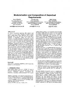
Figure 5: The three main elements of a product configuration system (Brathaug et al. 2008) There exist a number of options for the characteristics and features to be implemented in a configurator. The approach taken should pay attention to the specific aspects of the tendering phase for highly complex vessels, such as offshore support vessels. Figure 6 shows a schematic classification structure from (Blecker et al. 2004) that can be used to characterize a given configuration system.
11 / 56
Figure 6: Characteristics and features of configurators (Blecker et al. 2004) First, a configurator may be classified according to the type of configuration knowledge applied. For ship tender package development, it is likely that a rule‐based framework applying “condition‐consequence‐ action” types of rules is useful. This enables the continuous maintenance of the design knowledge by domain experts independently from the application that handles the design object and design process representation. Further, it enables this knowledge to be relatively easily made available to the “hosting” application through a rule engine. A rule‐based approach has been used extensively in the DNV Nauticus software suite, primarily for structural design, but also for modelling task automation in Nauticus Early Design. Applications in the conceptual ship design/tendering phase is still limited. Even if the knowledge in a rule‐based approach may be maintained independently, it will presuppose a certain structure of the product, i.e. what parameters and modelling elements are the rules allowed to operate on. Thus, from a more pragmatic implementation point of view, there will always be a choice when representing a certain unit of knowledge; should it be defined as an explicit rule, or as part of the underlying behaviour of the design model. In many cases the latter is preferable for both simplicity and performance, but may induce a long term maintainability cost as well as rendering the complete knowledge base intractable. Case‐based knowledge will still be important, but less for the direct configuration knowledge per se. Rather; it will be important for the evaluation and benchmarking of the emerging solution, as well as a basis for deriving the function‐to‐form type of relations from an existing design database. For the configuration strategy, assemble‐to‐order is likely to be the dominant approach, assuming that the design solution can be built by assembling design modules in a select‐scale‐arrange cycle. This has many parallels to building block design as described by (Andrews and Pawling 2007), and to arrangement optimization (Daniels and Parsons 2007) (Oers et al. 2007). Still, the current level of maturity in modularization is far from a point where it is possible to avoid a considerable engineering content in the process.
12 / 56
Further, the initial focus will be a configurator for a non‐distributed design team for the internal use by the sales or design department (though the future possibility of external use has been voiced, for the tender invitation development by customers, enabling a better understanding of design opportunities and consequences of requirements ‐ “requirements elucidation”). The complexity level of a configurator can be classified as primitive, interactive or automatic. A primitive configurator will mainly provide a pre‐defined structure in which the designer fills out the blanks, resembling a pure template‐based approach. It is useful for providing a structured and quality assured process, but will be too limited in achieving the required level of decision support. In an interactive configurator the human still has a significant role, but with added capacity of checking the validity of decisions, and guiding the configuration process. Automatic configurators further extend this into actually driving the configuration process forward in terms of adding parts and determining parameter values. While this may be applicable for certain sub‐processes, it is likely that the general approach still need to be that the human designer will have a central and decisive role also in a configuration‐based design process. Integration level is an important issue in determining the most efficient path towards a full scale implementation. While it is required that a configurator will need to be tightly integrated towards existing PDM, CAD and TDM applications, previous implementation projects have showed that having to take into account the full complexity level of such solutions will impede the development of the underlying processes, structures (modules) and knowledge base required for a long‐term, robust solution. Thus, we believe a stand‐alone front‐end is currently a better approach, alternatively an application where the end result is a collection of production type rules that can be imported into existing engineering systems to produce the tendering documentation at an appropriate level of detail. To summarize, modularization and product configuration go hand‐in‐hand, in terms of configuration defining a process in which the modules defined in the product platform development process are recombined specific product variants customized towards the end customer.
Lean Manufacturing Principles The underlying principle in Lean Manufacturing is to “shorten the production flow by eliminating waste” (Liker and Lamb 2000). This paradigm grew out of the mass production philosophy, that by economies of scale had lead to substantial productivity increases, the most prominent being the car industry with Ford as a frontrunner. The traditional mass production concept thrived in a situation where the industry was able to sell whatever they produced, despite involving batch production that tended to pile up as inventories in the production chain. However, the problems with this approach became more apparent as more models and variants were being produced to serve the individual needs of different customers. As a response to this, Toyota started to develop the Lean Manufacturing principles in the 1950’s, with the goal of simultaneously achieving” high quality, low cost, short lead time and flexibility” (Liker and Lamb 2000). This approach was further migrated to the Toyota suppliers, and then to the US in the late 70’s. In parallel to this, Japanese shipbuilders adopted lean principles, that together with other similar
13 / 56
initiatives such as TQM, JIT and 5S1, helped them have an impressive productivity increase in the whole period from 1960 to 1995. The connection between Lean Manufacturing and Modularization is not obvious, but is likely to comprise some of the following elements: •
The relation between short lead time/JIT value chains, and the procurement strategies enabled by a proper modularized approach
•
Modularization strategy – sizes to synch production?
•
Modularization opens up for outsourcing – having impact on JIT and product quality
•
Modularity related to product management, while lean thinking is a process management principle
1
TQM – Total Quality Management, JIT – Just In Time
14 / 56
Motivating Modularity Different stakeholders have different motivation for modularization. Key drivers can be summarized as: • • • • • •
Product variety and customization Production efficiency Reduced lead time Product development and design Reduced risk Outsourcing and globalization of supply chain
The drawbacks can be summarized as: • Less optimized physical architecture, increased weight and size • Less optimized performance, excessive capability • Risk of product similarity
Reduced Lead Time and Rapid Response in Tendering An important motivation for a modular product platform is reduced lead time in responding to tender invitations. Today, even for routine designs, it is quite common that the tender response is started form a previous tender, possibly for another customer with slightly different requirements. This is then “cleaned” for project specific content, and the particular requirements for the current customer are incorporated. Typically, the tender documents need to be checked with the different disciplines, such as structures, machinery and electrical. Obviously, both quality and response time are under pressure. With a modular product platform, with a well‐structured configuration system on top, this process may be considerably improved both in terms of efficiency, quality, and reduced risk, as well as indirectly through increased likelihood of winning the contract.
Figure 7: A modular product platform may improve the efficiency and quality of tender project development, and possibly leading to both increased handling capacity and higher hit rate
15 / 56
Effects on the Ship Production Value Chain The core question here is to what extent there is a connection between the shipyard’s modularization strategy and the supply chain structure. And given that this connection exists, which one is the “cause” and which one the “effect”? Historically, the research and development related to two different subjects of modularization and outsourcing, respectively, has taken place in different communities, the former as a design and manufacturing principle in engineering communities, while outsourcing has been discussed within the realms of economics, management and strategy (Fixson et al. 2005). Obviously, the product’s architecture determines the opportunities for manufacturers outside the company boundaries to produce individual components to be part of the final product. A classic example referred to in many papers is the modular structure introduced with IBM’s 360 system. This opened up for individual manufacturers to provide components to this platform, eventually driving prices down and making components such as hard drives and memory chips commodities. The impact that modularization has on the production value chain may also lead to changed power balances between the different actors in the value chain. One example is the shift in control over the specification. In a more “traditional” process the shipyard to some extent play the role of a sub‐ contractor designing and developing a solution constrained by the requirements in the outline specification. With a modular, product platform‐based design, this is shifted towards a situation where the owner is, at least in principle, selecting from a set of possible designs derived from a platform. Thus, the yard has to some extent regained the control of the specification.
Modularization in a sustainability perspective Given the current focus on both global warming and environmental issues, both in shipping and in society as such, the following question becomes pertinent: “To what extent can modularization contribute to sustainable shipping?” There is no obvious direct relation between modularization and emissions, and for most practical purposes they should be considered separate issues. Sustainability and environmental efficiency is primarily related to the functional performance of the technical solution. Whether a modular or an integral solution is used to realize this solution is of lesser importance. Still, there are indirect effects of modularization that may influence the environmental footprint of the solution, both in a positive and negative direction. This includes: •
Modularity comes at a price in terms of size and weight. An integral architecture with the same technical performance will typically be more energy efficient. Thus, from this perspective modularity has a negative environmental impact.
•
Modularity may contribute to a higher degree of customized solutions, thus improving the mission‐specific efficiency of the solution, with a corresponding positive environmental effect.
16 / 56
For ships, this effect is likely to be small, since the design is typically highly customized regardless of the chosen product architecture. •
Modular concepts aimed at providing operational flexibility, such as the Littoral Combat Ship, may contribute to a cost‐efficient modernization of obsolete equipment, upgrades, and adaptation to changed external conditions (new markets, trades, regulatory regimes, etc.). This may both contribute to increasing the operational efficiency of the vessel, as well as extending the vessel’s operational life.
•
Modularity may contribute to a more efficient recycling of the vessel along the interfaces defined by the modular architecture, and possibly also to the reuse of those components for which the economic life time is longer than for the ship itself.
17 / 56
Modular structures In this chapter, a number of approaches to defining modular structures are briefly reviewed, with some generic examples from various industries. In the next chapter, some more marine specific examples based on modular structures are discussed in more detail.
What is a modular structure? Recalling the previous chapter covering product architecture, we may define a product both from the perspective of function and form. In the product design process, we assign the physical building blocks – “chunks” – to the different functional elements. This can be illustrated in a very simple example. Consider two basic functions for seaborne transport vessel:
F1: F2:
Provide cargo support Provide thrust through water
In a traditional design, these two functions are, at a high level, allocated to a single ship “chunk”. To the extent that this overall chunk can be separated into a hull module and a machinery & propulsion module, the interaction between these modules are complex and not well defined. For instance, an increase in speed would typically require a larger and heavier propulsion system that in the next step would require an increase in hull displacement. Thus, these two modules have a high degree of dependency, which is a typical characteristic for integral architectures. In general, integral Figure 8: The high level architecture of a ship can be architectures are characterized by the characterized as a typical integral architecture following properties (Ulrich 2008): •
Product functions are imple‐ mented using more than one chunk or module
•
A single chunk or module implements many product functions
•
There is a high degree of (complex) interaction between the product modules
18 / 56
The opposite of an integral architecture is a modular architecture. Here, the different functions of the product are, to the extent possible, allocated to separate product modules, and the interaction between these modules is small or non‐ existent. For the seaborne transport example, a more modu‐ lar architecture could be achieved by separating the system into a cargo unit, such as a barge, and a propulsion unit, such as a tug. In this case, an increase in speed would only require a change in the “tug module”, and not per se influence the “barge module”. Figure 9: Assigning the cargo support and thrust provision function to separate modules provide a more modular architecture (However, this functional inde‐ pendence does not hold the opposite way). A similar concept have been developed as part of the EU project CREATE3S. Here, a common vessel platform has been developed, that can be mated with several different types of cargo modules.
Figure 10: Vessel platform with cargo modules, CREATE3S project Thus, a modular architecture can be defined by the following properties (Ulrich 2008): •
A single chunk or module implement one or a few product functions
•
The interaction between the module is limited and well defined
Modularity types There is some disagreement in literature on how many basic types of modularity there is. In (Ulrich 2008), three types are identified: •
Slot modularity, where the interface is specific to the module type. An example can be seen in Figure 10, showing a US Navy concept that allows for different configuration and rapid refit, but with a predefined location for each equipment type where the appropriate interface slot is available.
19 / 56
Figure 11: Slot modularity in US Navy TES concept (Jolliff 1974) •
Bus modularity, where the interface is standardized across several module types. This type of modularity is required when different selections and combinations of (equipment) modules are used to customize the product towards different purposes. One example
20 / 56
Figure 12: Example bus modularity interface for US Navy SEAMOD vessel, where different equipment packages can be connected to a standard interface (steel frame, power, water, signals, …). The purpose was primarily to increase the ability to meet different mission requirements (Jolliff 1974)
Figure 13: The Littoral Combat Ship is another example of bus modularity, where different mission modules, packaged as containers, can be plugged into a standard interface to provide a wide array of different mission capabilities •
Sectional modularity, where there is no “platform” module in which the other modules attach. Rather, all modules have one or a few common interfaces, which typically allow a larger variety in the physical layout of the product. On a ship, piping and HVAC systems typically exhibit sectional modularity. 21 / 56
Figure 14: Ship piping system, illustrating sectional modularity
Figure 15: The SIGMA Modular Ship, combing standardized hull sections to customize vessels with respect to mission and size In the figure on the next page, a more detailed division into different modularity types is given, from (Christiansen et al. 2003).
22 / 56
Figure 16: A more detailed division into different modularity types, from (Christiansen et al. 2003)
23 / 56
Review of Modularization in the Maritime Industry As have been discussed earlier in this report, the extent of modularization in shipbuilding is relatively limited. The dominant tradition has been based on “built‐to‐order”, “one‐of‐a‐kind” solutions. Still, there have been numerous initiatives and projects that in part have contributed to a body of knowledge that may serve as a platform for the further development and more extensive use of modularization in this industry. In this chapter, I will try to give a brief overview over some of these initiatives, both from Norway and from abroad. The list is by no means exhaustive, but may serve as a first starting point for further elaboration and investigations.
Overview The table below lists a number of Norwegian projects that are either directly or indirectly linked to modularization. A number of these projects were managed by the Shipyard Group at Marintek. This activity at Marintek was terminated in 2001, and part of the shipyard activity was continued in the Marintek spin‐off company proNavis.
Norwegian projects and initiatives Equipment, modularization and arrangement (Utstyr, modularisering og arrangement, 1992)
Anders Utkilens Rederi Identify factors important for selecting and designing module‐based Aukra Industrier Barber Ship Mgmt, arrangement solutions Wilh Wilhelmsen Lines, Kværner Warnow Det Norske Veritas UNI Storebrand Marintek
Rational construction (1999)
Brunvoll Nyborg Ulstein Bergen Ulstein Propeller UMOE Schat Harding Wärtsilä NSD Norway Marintek
QFD‐based method for improving the product structure and design based on the grouping of requirements and the corresponding mapping to components and modules (Buhaug and Langset 1999)
Early outfitting (Tidligutrustning)
Marintek Ulstein
Best practices for imporved design, planning and production processes at Norwegian shipyards
24 / 56
Early procurement (Innkjøp i salgsfasen)
Marintek Ulstein
Contain extensive material related to the functional modeling of core ship systems. In this project this is mainly used to form the backbone of the procurement plan and the content of the specification packages. This is likely to useful as an aid to define the modular architecture as part of an modularization strategy
MODNET (2004)
Ulstein Brunvoll Kongsberg DNV m.fl.
Develop and test new methods for busienss development, design, production, operation and sales of modul‐based ship solutions from a global collaborating industrial resource network – the Utvikler og tester ut nye metoder for forretningsutvikling, prosjektering, produksjon, drift og salg av modulbaserte skipsløsninger fra globalt samvirkende industrielle ressursnettverk – MODNET konseptet
Equipment, modularization and arrangement (1992) The project “Equipment, modularization and arrangement” (Utstyr, modularisering og arrangement) was a pre‐project with participation from MARINTEK, together with Anders Utkilens Rederi, Aukra Industrier, Barber Ship Management, Wilhelm Wilhelmsen Lines, Kværner Warnow Werft, Det Norske Veritas, and UNI Storebrand. The purpose of this pre‐project was to identify those factors being most important for selecting and designing module‐based arrangement solutions. Life cycle cost factors for a chemical tanker and a RORO vessel was used as a basis. The conclusions from this project can be summarized as follows: •
“There is no free lunch” – the benefits of module‐based solutions will need to offset cost increases in other areas
•
The life‐cycle cost distribution among various types of vessels was fairly similar, indicating that the potential savings as well can be found in the same areas
25 / 56
•
From a ship owners perspective, there are substantial potential benefits if the correct decisions are made already at the design stage
•
The most important cost driver in a life cycle perspective are the machinery systems, and the systems for cargo handling
•
The recommended focus for a larger main project should be on developing an LCC‐based modularization framework for the machinery and cargo handling system, and to develop robust and efficient interfaces for foundations, piping and cabling.
As we can see in the figure below, the incentives are different for the various stakeholders with respect to modularization. While the ship owner is inclined to focus on solutions that are efficient in operation, the yard will give preference to those solutions that will lead to decreased time or cost in production. As a consequence, the solutions specified from the ship owner in the outline specification, being considered preferable from a pure operations point‐of‐view, may show up to have a higher life‐cycle cost than alternative solutions due to a high realization cost for the yard. Thus, care should be given in the specification process in order to strike a good balance between the multiple stakeholders interest. Alternatively, the yard and ship owner, as well as main systems suppliers, should jointly develop the overall design and general arrangement.
Figure 17: Different stakeholders have different incentives for modularization (Hagen 1998) The project report also summarizes some of the mechanisms that may impede or hinder modularization in shipbuilding. This includes:
26 / 56
•
Technical factors, such as reduced freedom to exactly specify exact performances (but rather select from a limited set of predefined or configurable variants), and reduced freedom to optimize arrangement such as placement and minimization of piping length.
•
Techno‐economical factors, such as increased weight because of standardized foundations, increased area and volume requirements.
•
Price competition vs. collaboration, i.e. the degree of interaction required to define and develop good modularized solutions may be in conflict with a competitive tendering/souring policy to keep prices down
•
Procurement, capital binding, larger system modules may require a larger share of the equipment to be installed at an early stage in the production process (say, complete cabins with furniture). This may increase the finance cost of the vessel. However, this is likely to be the same as for an alternative early outfitting strategy.
•
Production, in terms of requiring an increased capability in handling larger modules, and for maintaining openings and passageways for access and transport.
Rational construction (1993) The purpose of the project was to develop methods and tools for increasing the flexibility of product configuration. This resulted in a QFD‐based method for improving the product structure and design based on the grouping of requirements and the corresponding mapping to components and modules. The method was based on subdivision of the product into functional elements, for which the interfaces were defined for power, mass and signal transfers and interactions. This is illustrated in Figure 17. Transferring these elements and interactions into a diagram (Figure 18), a mapping to physical component can be made. Based on the interactions identfied here, an appropriate modular architecture can be found, as illustrated in Figure 19.
27 / 56
Figure 18: Block diagram for a thruster unit (Buhaug and Langset 1999)
28 / 56
Figure 19: Connecting functional and physical elements for a thruster system (Buhaug and Langset 1999)
Figure 20: Identifying possible modular architectures by using the diagram to identify opportunities for splitting, grouping, redesign and using adapters(Buhaug and Langset 1999)
Early Outfitting The focus of this project was primarily on the splitting of the vessel into zones that to a certain extent can be outfitted independently of other zones. The topics covered were mainly Zone oriented 29 / 56
production, Outfitting Matrix, Module building – work packages, aimed at reduced lead times through standardization and lean production. “Design for production” – core principles 1. 2. 3. 4. 5. 6. 7.
Standardisation Interface minimization Aggregation Integration Modularization Flexibility CAD systems supporting early outfitting and modularization (topological “black box” modeling)
Sales Phase Procurement (1999) The aim of this project was to develop a rational methodology supporting the procurement process in shipyards. This was a collaboration project between Ulstein Yard and MARINTEK. A core topic was the procurement of project critical equipment, where a coherent framework for performance‐based specifications was developed.
401.001 RUDDER
402.016 LUBR: EQUIP.
403.012 STO. TANK
875.010 POWER SUPP. 24V
402.007 AXEL BEARING
403.012 EXP. TANK
403.055 CONTROL SYSTEM
402.001 RUDDER AXEL
403.007 STEERING GEAR
403.060 STARTER
875.010 POWER SUP. Relay box
263 FOUNDATION
These specifications were based on a functional modeling of core ship systems. These are used as a backbone for the procurement plan, and for identifying the scope, content and interfaces of the individual specification packages. Thus, this project may provide valuable input to the process of defining the required modular architecture to serve a global sourcing strategy.
30 / 56
*‐*‐* The next section contains a brief review of modularization strategies applied to specific phases of the ship development process.
Tendering and Specification Development2 One of the potential benefits of modular architectures is the combination of short lead time, rapid configuration combined with customization. These features are highly relevant in the ship tendering process. For shipyards and designers, a key competitive factor is their ability to efficiently respond to a tender invitation with a high quality tender that meets the customer’s needs. The main final delivery from the tendering process is a specification. This specification is frequently developed through stages, starting from a purely functional (often termed brief) specification, through a more performance oriented (often termed outline) specification, and potentially ending up as a detailed technical specification (often termed full). The typical full specification that exists at contract signing may have an extent of 150 to 300 pages covering 150‐400 system groups, describing in relative detail the product to be delivered. The specification is accompanied by a number of supporting documents, among them arrangement drawings, system drawings, and makers list. In addition, an internal cost calculation is developed in parallel to determine the bid price. The current typical approach to developing new specification document is to copy an existing specification from similar designs in previous projects. This document is then modified to accommodate the specific requirements of the new customer. In (Hagen and Erikstad 2002) and (Erikstad and Hagen 2003) the quality costs related to this approach is discussed. For instance, specification errors are typically and repeatedly copied into new specifications, as are customer‐specific requirements that were valid in the previous projects. Also, this approach will tend to hinder development as new projects frequently are based on old solutions. The results may be higher cost, higher uncertainty, outdated designs and reduced competitiveness with respect to winning the bid. One example of a tender development support tool based on modularization principles is DNV Software’s TenderSuite. TenderSuite is a web‐based tool for handling the concurrent, distributed
2
This chapter is partly based on excerpts from (Year). "IMDC 2009: the Thent International Marine Design Conference : May 26-29, 2009." IMDC, IMDC09 ; Tapir, Trondheim, 2 b, Erikstad, S. O., and Hagen, A. (2003). "Web-based tendering collaboration in project-centric industries." In: COMPIT - 2nd International Conference on Computer and IT Applications in the Maritime Industries, Hamburg, Germany, Erikstad, S. O., and Hagen, A. (2006a). "Applying Product Platform Technologies in Ship Specification Development." In: International Marine Design Conference (IMDC), Ann Arbor, MI, Hagen, A., and Erikstad, S. O. (2002). "Collaborative Ship Specification Development - From MS Word to Argus." In: International Conference on Computer Applications in Shipbuilding (ICCAS), Malmö, Sweden.
31 / 56
configuration and development of the specification document and the accompanying internal project calculation in project‐oriented industries. TenderSuite is based on a module oriented, product platform approach. One of the main differences is that while in a traditional approach (close to) all tendering‐related resources are spent in the development of individual projects, a platform approach will require two separate processes: •
Product platform development, comprising all activities related to the establishment and maintenance of the platform from which the individual projects will be generated in the different families of products. This process can be further divided into two phases. The first phase is the initial establishment of the product platform. Important decisions in this phase are the structure and scope of the platform, the number of product types, and the classifying dimensions of the type hierarchy. In the subsequent, these types will be referred to as product templates. The second phase is the continuous maintenance of the platform. In this phase, input is both received from design‐related activities independent from specific projects, and from the technology developments within concrete projects
•
Product platform exploitation, comprising the customer‐specific delivery projects, based on the configuration and further refinement of the product platforms with the intent to adopt customer‐ or project‐specific requirements. The efficient exploitation of the product platform is as much a matter of process know‐how as of product know‐how.
The platform development and exploitation process is illustrated in Figure 20.
Figure 21: A platform‐based approach consists of a modularization and platform development process, and a platform exploitation process (Erikstad and Hagen 2006a) One important question that arises in a platform‐based approach is the allocation of resources between development and exploitation. Allocating more resources for the modularization and platform development process is expected to reduce the effort and improve the quality for each specification project. However, for a given resource, each additional resource unit spent in the platform development phase will imply one resource unit less spent in the exploitation process. Thus, we should continue
32 / 56
spending resources in platform development as long as the net productivity and quality profit for the remaining projects in the exploitation phase is positive. The correct trade‐off is difficult to determine in project centric industries like shipbuilding, partly due to lack of efficient indicators, and partly due to the fact that it is often difficult to a priori assess how many projects that can be expected to share the initial development cost. Methods to support the negotiation of these trade‐offs include identifying (a) what parts of the total product portfolio may be most cost‐ efficient to invest resources in developing sound product platforms and (b) where it may be most feasible to create few flexibly configurable and general platforms as opposed to several more specific ones. This is a matter of clustering and analyzing historic projects to identify commonalities and differences, and will be a matter of further research. In TenderSuite, a “template” corresponding to the product type forms the starting point for the product configuration process. A template is a selection of nodes in the system breakdown structure that are relevant for a particular type of vessel. For each of these nodes there exists either a boilerplate text for the system specification, or an enumeration of variant descriptions to be selected from. Vessel
Chemical tanker
RoRo
Offshore vessel
PSV
Anchor handler
Supply
UT745
Figure 22: The product types in a tendering context, represented as an inheritance hierarchy of templates The different templates within a platform each form a unique starting point for a new specification, which will be further configured and developed to adhere to each customer’s requirements. Still, there will be a high degree of commonality among the templates, in particular for those systems that are not ship‐type specific. If all templates were to be developed and maintained in parallel, without efficient means to handle common resources, the efficiency of using the platform would decrease dramatically. Since each product platform may contain between 150 and 400 various system groups, many of which share properties across templates, it is important that the system can handle commonalities efficiently. A company that introduces a product platform approach “… without concern to the underlying product structure risks (a) to create a situation where [it] gradually looses … oversight and (b) [the ability to]
33 / 56
exploit the real potentials that resides in a well‐prepared and ‐founded [product platform] strategy.” (Hagen 1999) Thus, templates are organized into template hierarchies, where each template only defines what is different from a parent template. All other resources, including system existence and content, are inherited. In (DRM 2005), a product family is defined as “a set of individual products that share common technology and address a related set of market applications”. In the template structure defined above, each parent node will thus define a product family, each family recursively being part of a larger family, with broader scope but less specialization, as we go upwards in the inheritance hierarchy.
Figure 23: Core components of a specification product platform. Here, the variants corresponds to modules, and the System Breakdown structure combined with the Template Library define how these modules can be combined into “valid” specifications The development of a specification product platform follows a stepwise process that to some extent will be similar to developing a modularized product architecture and platform. A typical starting point is a situation where accumulated knowledge and experience is primarily stored implicitly as archived projects and tacit human capital. The goal is to reach a situation where this knowledge and experience is made explicit and becomes operationally available as part of a platform. The initial development of the platforms may be divided into 5 major steps, as follows (Erikstad and Hagen 2006b):
34 / 56
1. Identify product families and corresponding platforms Divide the current product portfolio into families. The grouping should preferably be based on system structure and/or content commonality, but may be influenced by market segmentation and organization structure. These families may each correspond to a separate product platform, or they may be grouped together to form larger platforms. 2. Determine System Breakdown Structure Determine a system breakdown structure (SBS) for each product platform defined in Step 1. The SBS captures the scope of each platform, and is the main organising hierarchy across projects and templates (or types), as well as for the variant library. The SBS may be seen as the system library with which to construct all possible platforms for all foreseen templates within that overall product family. This corresponds to defining the functional schematic in a modular architecture development process.
3. Determine major templates Within each platform, capture the set of distinct types to be supported by defining templates. Each template defines a particular (product) type upon which new project instances may be based, and will be increasingly specific with the depth in the (specialization) hierarchy. System groups from the overall SBS may be eliminated for each level of detail. Template (or type) formation may be internally driven by system and content commonalities, or externally driven by markets and models.
4. Populate the template structure Once the template configuration (structure) is defined, populate the content in system groups in the templates using knowledge embedded in existing projects. Exploit vertical type commonalities by using a (type‐subtype) inheritance mechanism, wherein content with relevance across several templates are defined at a more general level – above these “relevant” templates. The result from step 3 and 4 is a defined product platform upon which to base new project (specification) instances.
35 / 56
5. Capture cross‐type similarities as variants When the template (or product type) specific definitions are established identify standard options and commonalities across types (horizontal) by defining sets of variants for specific systems. Such variants constitute project‐ and template independent libraries of system descriptions for reuse. These descriptions may be relevant across several templates, for instance as different options pertaining to different product types.
Step 1: The identification of product families and corresponding platforms At the outset of the platform definition process, a core question is how many platforms should be supported within the organization. One possible assumption is that one such platform corresponds to one system breakdown structure that defines the ”dictionary of all possible systems” in that family, as well as a valid hierarchical structure. In other words, the SBS contains all possible system groups that are considered sufficient to describe all possible products in the product family. One single platform, or product architecture, has the benefit of being less costly to establish and maintain, and makes it possible to exploit common resources across all projects, and product variants, in the company. Such resources may, in addition to templates and variants, be libraries of rules of thumb, system interfaces, list of suppliers organized according to the SBS, and so forth. However, maintaining only one SBS is of course contingent that there in fact are sufficient commonalities to exploit. If not, a single platform will provide a poor “signal‐to‐noise” ratio, defining a common basic structure that is too general to be useful in concrete projects. This may be the case for a company both building merchant and naval vessels, where an SBS that fits both purposes equally may rather be equally poor than equally good. What has been common in the Norwegian maritime industry is a single platform is suitable for most ship consultants and shipyards that develop designs and projects in a small to medium‐sized product range. To some extent, this is due to the fact that there is already a well‐established system breakdown structure, the SFI3 system, which is used across most types of shipbuilding projects. These projects range from small offshore supply and fishing vessels, to larger passenger ships. Even for yards and ship consultants having a relatively wide product range, the fraction of system groups reoccurring across projects is fairly high. As discussed before, this is not a pure functional breakdown that would have been preferable when developing a modular product architecture, but is useful for a specification platform since it represents a de facto common structure across projects.
3
A system developed by the Norwegian Shipping Research Institute (SFI)
36 / 56
Multiple platforms are particularly useful when the company is targeting relatively different market segments. One case is a design and engineering company that develops designs both for ships, offshore and land‐based process industry. There is little overlap in the systems specification between these markets, and the projects are structured fundamentally different. This is an obvious case for multiple platforms. Different structures based on the same information content can also be maintained as views or mappings from a common base structure. However, this would require a predominantly one‐to‐one mapping between the individual systems description. Experience from developing mappings between four of the most common group systems used in North European shipbuilding indicate that the percentage of many‐to‐many mappings is too high to render a mapping‐based approach viable. The key aspects to consider when evaluating how to divide into top‐level product families are: •
To what degree projects may be divided into distinct clusters, in which the fraction of functions or systems relevant only for each cluster is high. A high such fraction points to the establishment of different product families.
•
To what degree there is value in reuse of information across the clusters, or to what degree equivalent systems vary in description. A low reuse value points to the establishment of different product families.
For the first of these criteria it is possible to establish a quite tangible metrics, focusing on the set of functions relevant only to the cluster of projects versus the set of functions relevant to both. The second is less obvious and difficult to measure, and may require some measure of semantic similarity in the textual descriptions. Step 2: Determining the system breakdown structure in each product platform The main objective when constructing these SBS, which often are function‐ or system‐oriented hierarchies, is that they should be wide enough to include all functions or systems that are relevant in the specific product family. For instance, it would be expected that an SBS for naval ships would highly focus functions related to weapons systems, which will not be the case in commercial ships. Typically, companies use one or more SBS that are customized to adequately describe the products they produce or their way of designing, engineering, procuring or producing. As stated before, we consider a group system to be the natural backbone for the information content in a specification‐oriented product setting. It defines the boundaries for the total scope of the derived platforms, identifying a set of building blocks as well as the relations (typically kind‐of or part‐of) between these building blocks in a hierarchical structure.
37 / 56
Figure 24: Example from the SFI group structure The SFI group system used extensively in the Norwegian maritime industry has been mentioned previously. It contains about 550 nodes arranged in a hierarchical structure comprising most systems found on commercial ships.4 A partly expanded view of SFI is shown in Figure 23. SFI is mostly a kind‐of (classification) hierarchy, but partly also a part‐of (composition) hierarchy. The degree to which the SBS is suitable for the purposes depends upon several factors. One important such is how well product platforms within the product family may be described in the same manner, or in the same detail. If some products in the product family contain a large fraction of systems being very widely described (through few system groups) while others are very detailed described (through many system groups), this is an indication of an imbalanced system. This is found in SFI, where for instance the huge “LNG Plant” is only defined by one system group while the significantly smaller loading/unloading of liquid cargo has several. Thus, SFI is significantly more adjusted to product tankers than to LNG carriers. The role of the group system is crucial in the platform definition process. SFI is for instance relatively limited in scope and has a narrow target, being originally constructed to suit the purposes of describing ship types like tankers, bulk carriers and RORO vessels. The contrast is the Norwegian standard for the offshore sector, NORSOK, which is very broad and designed to span several different kinds of products. The advantage with the prior is its simplicity, the disadvantage its lack of flexibility in defining any kind of ship. NORSOK, on the other hand, has the opposite characteristics. This is the obvious reason why yards
4
SFI also has a component-level detail code, expanding the number of groups to about 4.500, but this is not used to a large extent.
38 / 56
and design companies typically either will have developed their own group system or will have customized a standard one. Having been a de facto standard for the Norwegian shipbuilding community for decades, the SFI system has been an important backbone for collaboration and integration that has contributed to the competitive position of this industry today. To play the same role in the future, however, SFI needs to be updated to accommodate the changes in the structure and processes in shipbuilding, as well as provide a foundations on which emerging technologies, such as modularity and product platform technologies, can be based. Step 3: Identifying types to be supported in each platform Once the choice has been made as to how many product families to organize products into, and thus also how many and which system breakdown structures to use, the next step is to define the product type, or variant, hierarchy. In TenderSuite, this is called a template hierarchy. Each template represents in essence a particular product type, with its individual configuration based upon the product platform. However, the product becomes gradually more defined the further down in the hierarchy the template is defined, inheriting characteristics from its parent template. The “product” at the top level is simply “Ship”, while at the bottom level it may be a particular type‐designated design. For a ship consultant in the Norwegian specialized ship market, a natural choice might be to create a single SBS (and thus treat all products as belonging to one large product family). Further, this can be segmented into markets. Logical in this case is to split into two directions in the template; offshore vessels and fishing vessels. These clearly meet different market segments, and are in this case specializations of the template “ship” in the overall product family. In this process, the functions or systems in the product family SBS that are not relevant are removed, or “pruned away” and excluded from being used as resources in more detailed product templates. For instance, in the class “Offshore vessels” it is unlikely that the function “trawl winches” ever will be relevant, while in the class “Fishing vessels” the function “seismic systems” is not likely to be seen. The respective system groups exist as general resources, but are not visible as part of the product definitions neither on the product template fishing vessels nor any derived from this, such as lower level templates like “trawler” or “seiner”. A central issue in this process is how to classify project into different levels in the classification hierarchy. The pragmatic and common approach will be to classify according to markets or trades, an externally driven approach. This may be efficient, but will not necessarily capture the commonalities where they exist across this division. For instance, if there is a class of products called “merchant” that distinguish itself from both fishing and offshore vessels (as also is the case in Rolls‐Royce, having a separate market segment for this trade), while fishing and offshore vessels have several commonalities, it may be most feasible to make this segregation at one level for then to further distinguish “fishing” and “offshore” at the next level.
39 / 56
The other approach is internally driven, related more to characteristics of the products than of the markets they serve. We propose that it is possible to develop indicators – “similarity indices” – to address this issue. One such indicator may be the set of common systems across products in a cluster versus the set of systems distinct to one particular cluster of projects. Set theory, binary clustering, semantic analysis and statistical methods used on historic projects are all techniques that may be used for this purpose. Notwithstanding the methodological foundation: At the bottom line the trade‐off will be based on a pragmatic decision, though in time upon sound (and objective) decision parameters. If there are many templates in several levels, this will enable and efficient exploitation since the projects will initially be well‐defined from detailed product definitions. The downside is that as the levels increase, so does the number of bottom‐level templates (and thus product definitions), also increasing the cost of development and maintenance. This also influences when to stop addressing specializations as individual product types (as templates) and rather specialize further through the concept of variants. Step 4: Developing the type inheritance hierarchy After the definition of the configuration of the product families and platforms in the template hierarchies, the next step is to develop their content. Typical for specifications is that some parts are relevant for most, if not all, specifications. For most ship design companies, this applies to parts of the specification dealing with general terms, standards and guidelines, terminology, and the like. These descriptions will be defined at a high level, to be inherited to all dependent templates. This is similar to a (selective) class‐subclass inheritance mechanism. If the descriptions of certain common ship systems are very similar across product templates it will be relevant to describe the system at a higher level, and inherit the description in the subclasses, and thus avoid the maintenance burden of multiple, similar instances. It is probable that, for instance, the value of reuse of descriptions of, for instance, ship‐general functions like “Anchor winches” or “Windlasses” may be reused across more product templates than “Trawler winches.” Through this mechanism, a specification generated at the bottom level in a template hierarchy (that is, a very specific product type) will be a result from extracting text fragments from the up‐most to the lowest level. It is not a trivial task determining the proper level where the content, being a textual description, is to be defined. The overall intention is to exploit the commonalities, both to support efficient development and efficient maintenance. It is an area for future research to develop the necessary metrics for this, based upon semantic similarity across projects, both parametric similarity and textually descriptive similarity. The challenge of finding out when to perform specialization of the description at a low level rather than inheriting from a higher level is a demanding one. Step 5: Developing a library of crosstype variants The template hierarchy developed in Step 4 is useful for handling large‐scale, systematic variations between different types of products (ships). However, the different options on a system level that a customer typically may choose from, is not efficiently handled by the template structure. Examples of this are different systems solutions (e.g. stabilizing fins vs. liquid stabilizers, hydraulic vs. electrical 40 / 56
mooring winches), different systems configurations (e.g. 2‐engine vs. 4‐engine main propulsion arrangement) or different makes (e.g. Sulzer vs. MAN BW). Thus, to handle system level options that are predominantly ship type independent, a collection of system variants can be made available through a library, as complete systems descriptions connected to a specific node in the breakdown structure. Variants are typically selected as part of the configuration process immediately after a new specification project is instantiated from a template, but are also available as a resource in the further refinement process. Propulsion System
System
Direct Drive
Diesel Electric
AziPod
Variant
CPP
Generator
Engine
Structure
Engine
B&W
MAN
Rolls-Royce
6-cylinder
8-cylinder
12-cylinder
Figure 25: Modular approach to handling complex variants A parametric system description would be preferable. However, the main challenge would be to maintain the parameter model and the textual model of the system in parallel, and to embed the parameter values into the text without putting constraints on how the systems are described. Another development area is complex variants, i.e. variants that impact more than one system group. To handle this, a combination of parametric variants and rules must be used. Again, the core challenge is to handle this in a text‐producing context, without increasing the perceived complexity of the system from a user perspective. In effect, this will imply a move towards a gradually more modular approach such as that illustrated in Figure 24. While the system breakdown structure and the template hierarchy should be developed to a high degree of completeness in the platform definition phase, the variant library will typically be a target for continuous change also during the exploitation phase. Technology development, changes in rules and regulations as well as new system solutions will typically incite changes in the library. These changes may originate either from sources internally in the company, or it may come from external sources such as suppliers or consultants.
41 / 56
Summary The walkthrough of a specification platform development process may seem slightly on the side with respect to the core topic of this report, being modularization. Nevertheless, it has been included since it involves many of the same steps and fundamental considerations as we find in a modular product platform/architecture development process, as well as it points to some of the special considerations that are related to the shipbuilding domain. Thus, it might serve as a useful starting point. Generally, the use of platform thinking in the tender development phase of the ship lifecycle requires a shift in focus, away from an individual project focus, and towards a platform resource base from which individual tendering projects can be derived. It involves a step‐by‐step process that will bring a specification‐producing company from a situation where accumulated knowledge and experience is primarily stored implicitly as archived projects and tacit human capital, into a situation where this knowledge and experience is made explicitly and operationally available as part of a platform. For this approach to be viable, a presumption is that the upfront investment in developing the platform will be offset by an increased total efficiency in the development of the individual tendering projects downstream. This presumption can by no means be taken for granted, and it is our experience that many companies fail in this effort. Often there is a lack of leadership, discipline, patience, organizational motivation and/or competence to overcome the initial hurdles and gain the required momentum to be productive in a platform setting. Sometimes the reason is as simple as a lack of time and dedicated resources to do the initial investment in the platform – the project to be delivered nest week is always more important than investing in long term benefits. The result is a downward pointing spiral, where the latest project (with all its mistakes) is a better starting point than one derived from the platform, with the consequence that the platform suffers a slow starvation and eventually dies. However, for those companies that are able to pass this level of “critical mass”, the main benefits have been a more structured process leading to higher quality specifications, and a shorter response time from the initial request for tender to a final tender specification.
Modularization in Ship Equipment Design and Production In the maritime industries, the product platform concept has been employed first and foremost with equipment manufactures. One example is Wärtsilä which has developed sales configuration principles and software. Their vision is that a significant part of the engineering and production planning, as well as price quotes, should be a direct result of the enactment of different configuration rules (Sortland 2001). Another example from the maritime industry is Rolls‐Royce Deck Machinery. They have performed extensive work in using modularization and product platform principles. This has caused a complete redesign of some product lines, significantly reducing the number of configuration elements. This is illustrated in Figure 25. The result is both in a significant increase in the range of possible product configurations offered to customers, a substantial shortening of development time for new products and both reduced costs and throughput time in the sales projects (Andreassen 2005).
42 / 56
Figure 26: The number of configuration elements before and after PDM project at Rolls‐Royce Deck Machinery. Source: (Andreassen 2005) Similar to the tender specification platform described earlier, primarily covering the needs of yards and ship consultants, modularization may be used for efficiently generating custom‐specific product manuals for ship equipment suppliers. One example of this is illustrated in Figure 26.
43 / 56
Figure 27: A modularized ship equipment catalogue for deriving customized manual from a common platform of manual elements (DNVP, 2003)
Modularization in Ship Design Processes In ship design and engineering, the application of product platform technologies has been more limited, particularly in segments other than standardized tonnage. Some of the important factors explaining this situation may be the complexity resulting from highly customized requirements and extensive inter‐ relationships between different systems. Further, shipbuilding has a culture for handicraft and less tradition for long‐term thinking, with an inherent focus on the individual projects rather than process improvements. And, compared to many other industries facing a similar complexity level (say, automotive and aviation), the typical length of a series in particularly European shipbuilding is short. This implies fewer projects to share the costs of developing a configurable product platform. One of the forerunners in Norway in this technology area has been Ulstein Design. Ulstein Design has developed a product platform for offshore supply and service vessels, and uses this platform to configure individual vessels based on customer requirements. Their vision is that the design reflected in the very
44 / 56
early specification phase shall be as consistent as possible with the downstream detail engineering, and in the end production, with as little (re)work as possible.
Figure 28: Selected products in the Ulstein Design portfolio. Source: Ulstein Design Andrews (Andrews 2003; Andrews and Pawling 2007; 2009) have during the last twenty years published numerous papers on early ship design methodology, advocating the importance of establishing a model that can be configured in different ways to support the exploration of alternative solutions, as well as providing a basis for understanding the impact of the initial requirements.
45 / 56
Figure 29: Configuration of a vessel from building blocks from a library, for rapid evaluation and requirements elucidation in early design stages, from (Andrews and Pawling 2009)
Figure 30: Large, general purpose warship broken down into construction megablocks (Andrews and Pawling 2009) A modular approach for arrangement optimization has been developed by both (Oers et al. 2007). Here, a set of modules to be contained in the ship is defined, and an optimization routine finds the solutions
46 / 56
that best balance a set of criteria. This requires the definition of a set of distinct modules, and their corresponding interfaces both with the ship platform and towards other modules.
Figure 31: Module‐based approach used in the arrangement optimization in the early design of a warship, in (Oers et al. 2007)
Modularization in Ship Production
47 / 56
The Damen Schelde Sigma Modular Ship The Sigma class is a corvette that is designed and built by Damen Schelde Naval Shipbuilding. “Sigma” is an abbreviation for “Ship Integrated Geometrical Modularity Approach”. In this design, the hull segments are modularized, and can be assembled in different numbers and sequences, thus using a sectional modular approach. Off‐the‐shelves equipment is used to the extent possible. The modular approach allows the client to configure a vessel out of these standard blocks, and different versions with 12, 13 and 14 sections have been sold to three different navies.
Figure 32: The SIGMA modular naval vessel from Damen Schelde
Modularization in Operation The incentives for modularization from an operational point‐of‐view may be: •
Later modifications, for instance because of new regulations, technical development, or changed operating profile/mission
•
Easy component/system replacement because of failures or breakdown
•
A maintenance policy based on component/module rotation and “offline”/”off‐site” maintenance. This module rotation maintenance can be found in the aviation industry,
•
A “service‐oriented” operating regime involving remote monitoring and operation, typically by the system supplier
48 / 56
The Littoral Combat Ship The goal with the Littoral Combat Ship program in the US Navy was to develop a near‐shore combat ship that could be developed at a low cost, and with a flexibility that made it possible to rapidly shift from one type of warfare to another. It consists of a base module – sea frame – that is the warship platform. In addition, a range of different modules may be plugged in, providing capabilities such as Anti‐surface warfare, Mine Counter Measures, Anti‐Submarine Warfare, Intelligence, Surveillance and Reconnaiss‐ ance, Special Operation Forces support and Logistic support. These mission modules integrate to the extent possible, into the sea frame’s command and control architecture.
Figure 33: The Littoral Combat Ship providing operational flexibility through replaceable mission modules in a bus modular architecture
49 / 56
Future Prospects for Modularization in Shipbuilding – From a Norwegian Perspective Previously in this report, we have seen that the process from a tender invitation is received to the complete tendering documentation is completed typically involve a large number of parties both within and outside the company. In this process, we have made an argument for a modular approach, with potential gains in areas such as lead time, efficiency, quality and product variety. PDM/PLM systems offer a technology platform to support the necessary communication and integration, both from a product, a process and a systems perspective. However, there is currently little knowledge and experience in linking the theoretical models to practical industrial solutions within this field. The acquisition of a PDM system will by itself offer little or nothing to amend this situation. Thus, there is a need to better understand how the complete tendering documentation, including the building specification, arrangement drawings, ship performance analyses and 3D visualization, can be consistently derived from a disparate set of models, and how the different activities, systems and parties can be integrated into a common process that can be subsequently handled in a workflow support system. Based on this, further research should focus on how modularization and product platform technologies can enable a transition from designing new solutions from scratch with a large engineering content in each project, into a situation where customized solutions are increasingly configured from a product platform consisting of standard components and parametric modules. Based on published results from other industries, there seem to be a potential for significantly reducing the time and resource effort required to develop a new design, while maintaining the ability to provide customized solutions. Examples of specific issues that will require further research and technology development are: •
Improved product modeling of ships, in particular from a systems perspective, to identify and define modules suitable for parameterization, and with minimal, well‐defined interfaces to be used as building blocks in the product platform
•
The identification of the significant set of parameters for each type of component or module, and the relation between those parameters and the performance of both the containing system and the complete design
•
The structuring and classification of components and modules into libraries, for efficient access in the configuration of individual design solutions. The definition of standard component and module types, variants and instances, and how these can be grouped together to form standard templates for different ship types
•
The development of process models and Best Engineering Practices for configuration‐based design process support from request to tender delivery
50 / 56
In the ship production phase, a modular approach offers a number of opportunities for improvements. First, it is an enabling technology for more flexible, and increasingly, global production chains. A clear modular structure, with well defined interfaces between the modular “chunks”, opens up for the outsourcing of a larger share of the total production. Alternatively, by enabling the reuse of standardized components across multiple design variants, it may provide a basis for a higher degree of automated production of longer component series. This may result in an insourcing of production, enabled by automated production that possibly is competitive in high‐cost countries like Norway. In the operations phase, a modular product structure may be a strategic platform for offering ships with a higher degree of operational flexibility in the future. This might be an instrument towards meeting some of the most imperative challenges we face today, in terms of higher demands for reduced emissions and energy efficient transport, volatile markets and an increased pace of technology changes and the emergence of new market opportunities. A key research challenge related to this is a better understanding of real options related to design: To what extent should the ship owner invest in future operational flexibility already at the newbuilding stage. Examples of such investments ranges from providing sufficient structural and powering support for upgrading cranes, to investing in hybrid powering systems and additional power reserves beyond what is required for the vessel’s first contract. A proper modular architecture may provide a more competitive cost‐benefit ratio for this. Also related to the operations phase, a higher degree of flexibility for handling multiple cargo types and integration into increasingly complex logistic transportation chains, a modular approach offers potential oppor‐ tunities in the future, as illustrated by the figure on the right from the CREATE3S project. This will require the current competence of Norwegian ship designers in developing innovative ship solutions, but also require research and development into a better understanding of how the requirements for future transport provide the ramifications for the next generation specifications in the first place. A final question to be asked is, to what extent is a modular approach applicable to the typical Norwegian shipbuilding domain, where the focus is primarily on highly complex, highly customized vessels? A final answer to this has not been given in this report. It is likely that the high complexity may increase the level of difficulty in developing a modular platform in the first place. However, it is likely that the potential benefit is also higher for complex vessels. A recommended strategy for handling complexity in general is “divide and conquer”, thus hiding the inner complexity of the parts so that a comprehensible system with well‐defined interfaces emerge. This was put forward by Herbert Simon already in 1962 by his seminal paper “The Architecture of Complexity”, and the current application of modular strategies in multiple high‐complexity domains, such as aviation and automotive, should serve as an argument for its relevance in the maritime field as well.
51 / 56
Reference List (2009). "IMDC 2009: the Thent International Marine Design Conference : May 26‐29, 2009." IMDC, IMDC09 ; Tapir, Trondheim, 2 b. Andreassen, T. (2005). "Module‐Based and Parametric Configuration and Engineering." In: Web‐IT Maritime, Ålesund, Norway. Andrews, D. J. (2003). "A Creative Approach to Ship Architecture." International Journal of Maritime Engineering. Andrews, D. J., and Pawling, R. (2007). "Research into the Use of Computer Aided Graphics in Preliminary Ship Design." In: ICCAS 2007, Portsmouth. Andrews, D. J., and Pawling, R. (2009). "The Impact of Simulation on Preliminary Ship Design." In: IMDC 2009 ‐ The 10th International Marine Design Conference, S. O. Erikstad, ed., Tapir, Trondheim, Norway. Blecker, T., Abdelkafi, N., Kreuter, G., and Friedrich, G. (2004). "Product Configuration Systems: State‐of‐ the‐Art, Conceptualization and Extensions." In: Eighth Maghrebian Conference on Software Engineering and Artificial Intelligence, May 2004, Tunisia, 25‐36. Brathaug, T., Holan, J. O., and Erikstad, S. O. (2008). "Representing Design Knowledge in Configuration‐ Based Ship Design." In: COMPIT 2008 ‐ 7th International Conference on Computer and IT Applications in Maritime Industries, Liege, Belgium. Buhaug, Ø. H., Arnulf, and Langset, J. (1999). Kravhåndtering: Økt fleksibilitet ved tilpasset produktoppbygging, MARINTEK. Christiansen, K., Kjeldgaard, J., and Tvenge, K. (2003). "Shaping Product Portfolios for the Future." V. M. Consultants, ed. Daniels, A. S., and Parsons, M. G. (2007). "Development of a Hybrid Agent‐Genetic Algorithm Approach to General Arrangements." In: COMPIT 2007, Italy. Ericsson, A., and Erixon, G. (1999). Controlling design variants: modular product platforms, Society of Manufacturing Engineers, Dearborn, Mich. Erikstad, S. O., and Hagen, A. (2003). "Web-based tendering collaboration in project-centric industries." In: COMPIT ‐ 2nd International Conference on Computer and IT Applications in the Maritime Industries, Hamburg, Germany. Erikstad, S. O., and Hagen, A. (2006a). "Applying Product Platform Technologies in Ship Specification Development." In: International Marine Design Conference (IMDC), Ann Arbor, MI. Erikstad, S. O., and Hagen, A. (2006b). "Applying product platform technologies in ship specification development." In: 9th International Marine Design Conference (IMDC 2006), Ann Arbor, MI, USA. 52 / 56
Fixson, S., Ro, Y., and Liker, J. (2005). "Modularisation and Outsourcing: Who drives whom?" International Journal of Automotive Technology and Management, 5(2), 166‐184. Hagen, A. (1998). "Utstyr, modularisering og arrangement Sluttrapport fra forprosjekt." MARINTEK, Trondheim. Hagen, A., and Erikstad, S. O. (2002). "Collaborative Ship Specification Development ‐ From MS Word to Argus." In: International Conference on Computer Applications in Shipbuilding (ICCAS), Malmö, Sweden. Jolliff, J. V. (1974). "Modular Ship Design Concepts." Naval Engineers Journal, 86(5), 11‐32. Liker, J., and Lamb, T. (2000). "Lean Manufacturing Principles Guide." MARITECH. Marintek. (1998). "Innkjøp i salgsfasen, sluttrapport ("Procurement in the Sales Phase, final report")." MARINTEK. Oers, B. v., Stapersma, D., and Hopman, H. (2007). "Development and Implementation of an Optimisation‐Based Space Allocation Routine for the Generation of Feasible Concept Designs." In: COMPIT 2007, Italy, 171‐185. Pahl, G. B., W. (1984). Engineering Design, Springer‐Verlag, Berlin. Schilling, M. A. (2000). "Towards a general modular systems theory and its application to interfirm product modularity." Academy of Management Review, 25(2), 312‐334. Simon, H. A. (1973). "The Structure of Ill‐structured Problems." Artifical Intelligence, 4, 181‐200. Simon, H. A. (1981). The Sciences of the Artificial, 2nd Ed., The MIT Press, Cambridge, Massachusetts. Simpson, T. W. (2003). "Product Platform Design and Customization: Status and Promise." In: ASME Design Engineering Technical Conferences ‐ Design Automation Conference, K. Shimada, ed., Chicago, IL. Sortland, S. (2001). "IT and Net‐Based Solutions in Product Configuration and Sales." In: Web‐IT Maritime, Ålesund, Norway. Ulrich, K., and Tung, K. (Year). "Fundamentals of Product Modularity." ASME Winter Annual Meeting Symposium on Design and Manufacturing Integration, Atlanta, GA, 73‐79. Ulrich, K. T. (2008). Product design and development, 4th ed. Ed., McGraw‐Hill/Irwin, Boston :. Wuuren, W., and Halman, J. I. M. (2001). "Platform‐driven Development of Product Families: Linking Theory with Practice." In: The Future of Innovation Studies Conference, Eindhoven, The Netherlands.
53 / 56
Appendix
Construction method
Production technology
Stick building
Piece part construction Multiple building positions on building ways Limited production equipment
Operations effect Long construction cycle time Sequential production operations Highly labor intensive
Block building Block assembly and erection on building ways or in a building dock
Reduced building positions
Reduced construction cycle time
Increased equipment
Parallel assembly of blocks
Excessive block assembly time
Some automated panel assembly
Narrow product range
Product oriented
Hierarchical interim product assembly throughout defined stages of construction
Single building position High levels of automation Maximized use of robotics
Long learning curve on 1st of class Minimum construction cycle time Totally integrated ship assembly Maximized labor / facility utilization Broad product range No learning curve on 1st of class
54 / 56
55 / 56
56 / 56