Australian Earthquake Engineering Society 2010 Conference, Perth, Western Australia
Moment Connections to Circular and Square Composite Columns Using Blind Bolts Huang Yao1, Helen Goldsworthy2, Emad Gad3, Olivia Mirza4, Brian Uy5
1. Research Fellow, Department of Civil and Environmental Engineering, The University of Melbourne, Vic 3010, Australia. Email:
[email protected] 2. Senior Lecturer, Department of Civil and Environmental Engineering, The University of Melbourne, Vic 3010, Australia. Email:
[email protected] 3. Professor, Faculty of Engineering & Industrial Sciences, Swinburne University of Technology, Hawthorn, Vic 3122, Australia. Email:
[email protected] 4. Lecturer, School of Engineering, University of Western Sydney, Penrith South DC, NSW 1797, Australia. Email:
[email protected] 5. Professor, School of Engineering, University of Western Sydney, Penrith South DC, NSW 1797, Australia. Email:
[email protected]
Abstract Moment-resisting frames with composite tubular columns are used extensively in multi-storey building structures in China, Japan and Europe. However the current moment-resisting connections tend to be quite complex, with extensive welding. This paper reports the results of a research programme that aims to develop economical semi-rigid to rigid connections that are simple to construct and are bolted on site. It uses an innovative approach using blind bolts with cogged extensions for the T-stub connections, and using blind bolts for the flush endplate connections. The results from full-scale tests on T-stub and flush endplate moment connections to concrete-filled circular and square hollow sections are presented. The objective of this work was to investigate the performance of the blind bolted connections, including failure modes, moment-rotation curves, load-deflection curves and ductility. The joint behaviour is evaluated by studying key components within the connections. The T-stub connections to circular columns are stronger and have a higher initial stiffness than their square counterparts. High initial stiffness and strength are achieved in the negative moment direction for the flush endplate connection, but they are significantly reduced in the positive moment direction.
Keywords: moment-resisting connection, strength, stiffness, blind bolts, structural hollow section, component
1. Introduction Moment-resisting frames with composite tubular columns are used extensively in multi-storey building structures in China, Japan and Europe owing to excellent load carrying capacity and economy in construction (Nakada & Kawano 2003, Han and Li 2010). However, the current welded moment-resisting connections with inner, exterior or through diaphragms tend to be quite complex and would not be used in Australian practice. Making conventional bolted connections to tubular columns is difficult due to the restriction of gaining access to the inside of the hollow sections. In order to employ on-site bolting to tubular columns, several types of blind fasteners have been developed to overcome the difficulty of accessing the inner side of structural hollow sections, such as Huck high strength blind bolts (Huck 1990), Lindapter Hollobolt (Lindapter 1995), Ajax Oneside (Ajax 2002), and flow drilling method. Studies conducted by Ghobarah et al. (1996), France et al. (1999), Loh et al. (2006), Wang et al. (2009) on connections to tubular column using Huck blind bolt, Hollobolt and flowdrill indicated that the strength and stiffness of the connection were limited by flexibility of column face and pulling out of those blind bolts. The Ajax Oneside blind bolt is a relative new product made in Australia and is able to achieve the full pretension load unlike its counterparts (Fernando 2005). This paper presents a research programme that aims to develop economical semi-rigid to rigid connections that are simple to construct on site using the Oneside blind bolt. Novel blind-bolted Tstub and flush endplate moment connections are developed to ensure sufficient strength and stiffness when they are used in moment-resisting frames in low to moderate seismic regions such as Australia.
2. Experimental program The experimental program is composed of two exterior joints and two interior composite joints. The test specimens are representative of exterior and interior beamto-column joints in two medium rise moment-resisting frames (Uy et al. 2009, Yao et al. 2009). The basic components of the test specimens are listed in Table 1. The experiments provide a study of novel joint systems used in composite frames to withstand earthquake loading. Table 1 Test specimens
Specimen
Column
Beam
Connection
Blind bolt
1
CHS304x6
460UB82.1
2
SHS300x8
460UB82.1
3
SHS300x10
610UB101
4
SHS300x10
610UB101
Curved T- M20 with stub extension Flat T-stub M20 with extension Flush M20 endplate Flush M20 endplate
Loading type Unidirectional cyclic loading Unidirectional cyclic loading Monotonic loading Cyclic loading
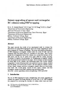
2.1 Steel connection to CHS and SHS column Test specimen 1 is composed of a concrete-filled circular hollow section, two curved T-stubs, and a universal steel beam as shown in Figure 1. Specimen 2, shown in Figure 2, is composed of a concrete-filled square hollow section, two flat T-stubs, and a universal steel beam. The T-stubs were fastened to the circular and square tubes by modified blind bolts with cogged extensions into the concrete core. The bind bolt and cog assembly consists of a bolt with circular head, a cog extension to the bolt head, a sleeve for shear, a split stepped washer, and a stepped washer as depicted in Figure 3. The cogged extensions welded to the head of the blind bolts were 24 mm diameter N type reinforcing bars of grade 500 MPa. The Ajax blind bolts have a minimum tensile strength of 800 MPa and yield strength of 640 MPa. A coupon test of a welded blind bolt with cogged extension was performed as a check on the weld capacity. It fractured at 211 kN in tension, and this was considered adequate for the purpose of the connection test. The tube was filled with concrete of 45 MPa target compressive strength. On assembly, all of the blind bolts to circular and square hollow sections and structural bolts connecting T-stubs to the beam were first tightened to a snug-tight condition and were then fully tensioned using the part-turn method.
Figure 1 Connection to CHS column
Figure 2 Connection to SHS column
The setup of the connection test is illustrated in Figure 4. The bottom of column was inserted into a socket plate which was bolted to the strong structural floor by pretension. The top of column was braced through a collar plate to the floor by four bracing members. An axial load of 800 kN (approximately 20% of the CHS column axial capacity for specimen 1 and 15% of the SHS column axial capacity for specimen 2) was applied to the top of the column through a rigid steel plate. The loading applied to the beam end consisted of a series of load controlled cycles (6 cycles at 60 kN, 120 kN, 150 kN and 4 cycles at 180 kN) followed by a series of displacement controlled cycles (2 cycles at beam end displacement of 75 mm, 90 mm); finally the specimen was loaded to failure. This was in accordance with the current AISC testing protocol for uni-directional cycling (AISC 2005). Six transducers were mounted on the top T-stub to measure the pullout of blind bolts, the deformation of the endplate and web plate, slip at the flange plate connection, and horizontal and vertical shear displacement of the T-stub relative to the column in the tension zone. Three transducers were fixed on the bottom T-stub in the compression zone to record the horizontal and vertical displacement relative to the column. An
additional transducer was installed on the ground to monitor the beam end deflection. Digital photogrammetry was also used as a supplementary approach to trace the deformation of the beam-to-column specimen and the potential relative movement between the specimen and testing rig. An initial survey was taken before the test to record the original conditions, then a series of surveys were performed after applying an axial load of 800 kN on the column, at beam end load levels of 30 kN, 60 kN, 90 kN, 120 kN, 150 kN, 180 kN, 210 kN, and at beam end deflections from 75 mm to 135 mm at increments of 10 mm. Afterwards, the specimen was continuously loaded to failure.
Figure 3 Blind bolt assembly
Figure 4 Test setup for blind-bolted connection
2.2 Composite connection to SHS column The composite flush endplate connection was designed to provide strength and ductility for earthquake resistance with energy dissipation located in ductile components of beam-to-column joints. The experiment comprises of two specimens, one tested statically and the other cyclically. Each specimen consisted of a 2000 mm wide, 3540 mm long and 150 mm deep reinforced concrete composite slab connected to a 610UB101 structural steel beam through shear studs as shown in Figure 5. The beam was connected to a concrete-filled square column of SHS 300x10 with flush endplate using Ajax M20 blind bolts. The slab contained closely spaced reinforcement in the longitudinal direction (N12@100) that contributed greatly to the overall performance of the connection region in the negative moment direction, in terms of both stiffness and strength.
Figure 5 Composite connection to SHS column
The aim of this series of experimental study was to monitor the load-deflection behaviour until the blind bolts reached their ultimate capacity. In specimen 3, an axial load of 1980 kN (about 35% of SHS column axial capacity) was applied to the centre of the concrete filled square column. Monotonic vertical loads were applied at both ends of the structural steel beams until the specimen reached its ultimate capacity. For specimen 4, a similar axial load (1963 kN, about 35% of axial capacity of column) was applied to the concrete filled tubular column. Both upward and downward cyclic loads were applied simultaneously to both ends according to the AISC bi-directional cyclic loading protocol (AISC 2005).
3. Experimental results and discussion 3.1 Failure mode and displacement of specimen 1 & 2 Specimen 1 achieved a maximum load of 282 kN at the beam end. It failed due to the fracture of the thin tube wall at the top row of blind bolts at the tension zone. This load is equivalent to an ultimate moment of 606 kNm at the column face. The deformation of the connection to the circular column is shown in Figure 6. Specimen 2 achieved a lower load of 265 kN at the beam end. It also failed due to the excessive deformation of the tube wall at the top row of blind bolts at the tension zone. This load is equivalent to an ultimate moment of 574 kNm at the column face. The deformation of the connection to square column is shown in Figure 7. In both tests the large outwards deformation of the tube wall is attributed to the group action of cogged extensions anchored in the concrete core and compounded by localised deformations due to the blind bolt heads bearing against the tube wall. In the first test this led to tearing of the tube wall. The displacement of the top T-stub is made up of the combined sum of the pullout of blind bolts with extensions, deformation of the tube wall, outward deformation of the endplate, stretching of T-stub’s web-plate, and slip at the flange plate connection. The displacement of the bottom T-stub comprises endplate bearing on the tube wall, deformation of the T-stub’s web-plate, and slip at the bottom flange plate connection. In the case of the circular tube specimen negligible deterioration of strength and stiffness was observed at the various loading cycles for loads up to 130 kN (moment of 260 kNm at column face). The stiffness of Specimen 2 deteriorated at a more rapid rate.
Figure 6 Failure of specimen 1
Figure 7 Failure of specimen 2
To examine the concrete at the anchorage zone after the test, the blind bolts and tube wall were cut away; the cracked concrete at the bolt line can be seen in Figures 8 and 9. Concrete in the square hollow section cracked more severely than that in circular column.
Figure 8 Concrete in circular column
Figure 9 Concrete in square column
3.2 Moment-rotation response of specimen 1& 2 The moment-rotation response of the blind-bolted connection is determined by combining the load versus displacement curves from the top and bottom T-stubs. The moment is calculated as load applied at the beam end multiplied by the distance between the load and the column face. The rotation is determined by the sum of the displacement of the two T-stubs at a given load divided by the beam depth. The moment versus rotation curves for the blind-bolted connection to the circular column and the square column are shown in Figure 10 and Figure 11 respectively. The response of the connection is almost linear for moments less than 260 kNm for the circular column section and 130 kNm for the square column section. The initial rotational stiffness, Sj,ini, of the connection is defined as the secant rotational stiffness up to a bending moment of 130 kNm, which is 145,343 kNm/radian for specimen 1 and 90,410 kNm/radian for specimen 2. A reduction in stiffness is observed when the connection experiences slip between the beam flanges and the stem of the T-stub for both specimen 1 and 2 at 300 kNm. This slip moment can be regarded as the effective yield moment for the connection. Therefore, the ductility of the connection can be calculated as the ratio of rotation at ultimate and yield, which is 6 for specimen 1 and 14 for specimen 2 satisfying the code requirement (AS1170.4-2007) on structural ductility factor for moment-resisting frames (2 for ordinary frames, 3 for intermediate frames, and 4 for special frames). In accordance with Eurocode 3, Sj,ini is compared to the flexural stiffness of the connected beam EIbm/Lbm to define the rigidity of a beam-to-column connection. The connection is considered to be rigid when Sj,ini is larger than 25EIbm/Lbm for unbraced frames and 8EIbm/Lbm for braced frames, pinned when Sj,ini is less than 0.5EIbm/Lbm, and is assumed to be semi-rigid when Sj,ini is between these two values. For a beam span of 8.4 m EIbm/Lbm is equal to 8857 kNm/radian. Therefore, Sj,ini is about 16 times EIbm/Lbm for specimen 1 and 10 times EIbm/Lbm for specimen 2. The blind-bolted connections to circular and square column can be classified as rigid for braced frames and semi-rigid for unbraced frames. Even though the thickness of the circular column is smaller than that of the square tube, the connection to the circular tube exhibits a
higher stiffness due to improved confinement. For the universal beam used in this test, the yield moment capacity of the beam is 483 kNm and its plastic moment capacity is 552 kNm. It should be noted that in order to test the ultimate capacity of the connection, the beam was deliberately chosen to be stronger than that required in the design of the frame. Hence the beam is stiffer than required so in the actual frame the stiffness of the connection relative to the beam is likely to be higher than the values given above. 700
700
Rigid-braced
Rigid-unbraced
600
600
500
500 Moment (kNm)
Moment (kNm)
Rigid-unbraced
400 300 200
Rigid-braced
400 300 200
100
100
0 0
0.01 0.02 0.03 0.04 0.05 0.06 0.07 0.08 0.09
0.1
0 0
Figure 10 Moment vs. rotation for specimen 1
0.02
0.04
0.06
0.08
0.1
0.12
0.14
0.16
Rotation (radian)
Rotation (radian)
Figure 11 Moment vs. rotation for specimen 2
3.3 Load-deflection response of specimen 3 & 4 Figure 12 shows the load versus deflection relationship for specimen 3 under static loading. The deflection was measured by transducers set at beam end loading point. When the load at beam end reached 229 kN (moment of 370 kNm at column face), fine cracks were observed close to the column support as shown in Figure 13. This can be regarded as yield point of the composite connection. As loads progressed, more fine cracks appeared at 314 kN (moment of 508 kNm at column face) with additional cracks at the end of the concrete slab. When the load reached 400 kN (moment of 648 kNm at column face), bending of the end plate was observed as shown in Figure 14. A peak load of 425 kN (moment of 689 kNm at column face) was measured as shown in Figure 12 with a 15 mm deflection. The maximum deflection was 75 mm with load reduced to 320 kN. The ductility of connection is estimated to be 12.
Figure 12 Load vs. deflection for specimen 3
Figure 13 Crack of slab in specimen 3
Figure 15 demonstrates the load versus deflection relationship for specimen 4 subjected to cyclic loading. Initially, fine cracks appeared near the column and towards the centre of the slab when the specimen was subjected to a 170 kN downward load (moment of 275 kNm at column face) as shown in Figure 16. The
cracks became larger with additional cracks opening up at 212.5 kN (moment of 344 kNm at column face) which indicated yielding in the composite joint. At an upwards load of 300 kN (moment of 486 kNm at column face) failure of the bolts in tension occurred at the bottom side. Negligible deterioration in strength and stiffness was observed under the loading cycles at each load step. Figure 17 illustrates that the bottom row of the blind bolts pulled out of the concrete-filled steel tube when the specimen was subjected to upward loading. The maximum gap between the top region of the end-plate and column was 5 mm, while the maximum bottom gap was 41 mm. The ductility of this composite connection is estimated to be 8, which is greater than the code requirement of AS1170.4-2007 for moment-resisting frames.
Figure 14 Flush endplate in specimen 3
Figure 16 Crack of slab of specimen 4
Figure 15 Load vs. deflection for specimen 4
Figure 17 Flush endplate in specimen 4
The results show that the proposed blind bolted composite connection with flush endplate behaves in a semi-rigid and partial strength manner and exhibits reasonable strength and stiffness. The experimental result also shows that the blind bolted composite joints have excellent ductility and can satisfy the requirements of the structural seismic design in Australia. The experiment on Specimen 4 showed that connection failure still plays a major role in medium rise buildings when they are subjected to earthquake loading. Modification of the blind bolts is required to improve the stiffness and strength in the positive moment direction.
4. Conclusions Full scale tests on blind-bolted moment connections to concrete-filled circular and square columns demonstrate the strength and stiffness which can be utilised in transferring moment between the beam and column within low to medium rise structural frames. Providing a cogged extension to the blind bolts improves the tensile
behaviour of the moment connection as the load can be shared between the tube wall and cogged anchorage within the concrete. Based on the moment-rotation response of the connection, the proposed blind-bolted T-stub connection to circular and square columns can be classified as a rigid connection for braced frames and a semi-rigid connection for unbraced frames. For the composite flush endplate connections the strength and stiffness in the negative moment direction is considerably larger than that in the positive moment direction due to the contribution of the slab reinforcement in tension in the negative moment direction and the flexible nature of the bottom blind bolts in tension in the positive moment direction.
Acknowledgements The authors would like to acknowledge the generous support of Ajax Engineered Fasteners, Australian Tube Mills and ARC through Linkage Project No. LP0669334.
References Ajax Engineered Fasteners (2002). ONESIDE brochure. B-N012 data sheet, Victoria. American Institute of Steel Construction Inc. (AISC). (2005). Seismic provisions for structural steel buildings, ANSI/AISC 341-05, AISC, Chicago, IL. Fernando, S. (2005). Joint design using ONESIDETM structural fastener. Technical note: AFI/03/012, Ajax Fasteners, Victoria. France J., Davison B., Kirby P. (1999). Strength and rotational stiffness of simple connections to tubular columns using flowdrill connectors, Journal of Constructional Steel Research, Vol. 50, pp. 15-34. Ghobarah, A. Mourad, S. Korol, R. (1996). Moment-rotation relationship of blind bolted connections for HSS columns, Journal of Constructional Steel Research, 40(1):63-91. Han, L.H. and Li, W. (2010) Seismic performance of CFST column to steel beam joint with RC slab: Experiments, Journal of Constructional Steel Research, 66, 13741386. Huck International Inc. (1990). Industrial fastening systems; Arizona, USA. Lindapter International Ltd, (1995). Type HB hollo-bolt for blind connection to structural steel and structural tubes; Bradford, England. Loh H.Y., Uy B., Bradford M.A. (2006). The effects of partial shear connection in composite flush end plate joints: part I – Experimental study, Journal of Constructional Steel Research, Vol. 62, pp. 378-90. Nakada, K. and Kawano, A. (2003). Load-deformation relations of diaphragmstiffened conncetions between H-shaped beams and circular CFT columns. Proceedings of the International Conference on Advances in Structures, Hancock et al. (eds), Sydney, Australia. Standards Australia (2007). AS 1170.4 – 2007 Part 4: Earthquake actions in Australia, Sydney, Australia. Uy, B., Mirza, O., Chalhoub, P. & Maenpaa, D. (2009) Experimental behavior of composite beam-column flush end plate connections subjected to low probability, high consequence loading. Behaviour of Steel Structures in Seismic Areas. CRC Press. Wang J.F., Han L.H., Uy B. (2009). Behaviour of flush end plate joints to concretefilled steel tubular columns, Journal of Constructional Steel Research, Vol. 65, pp. 925-939. Yao, H., Goldsworthy, H.M., Gad, E.F. (2009). Design and analysis of a case-study low-rise building with moment-resisting composite frames, Proceeding of AEES Conference, Australian Earthquake Engineering Society, Newcastle, Australia.