A total of fourteen half-scale reinforced concrete columns, divided into two groups, are ... WIT Transactions on The Built Environment, Vol 85, www.witpress.com ...
High Performance Structures and Materials III
419
Seismic upgrading of square and rectangular RC columns using FRP wrapping M. A. N. Abdel-Mooty1, M. E. Issa2, H. M. Farag3 & M. A. Bitar4 1
Department of Construction Engineering, American University in Cairo, Egypt 2 Department of Structural Engineering, Cairo University, Egypt 3 Department of Structural Engineering, Military Technical College, Egypt 4 Department of Structural Engineering, Military Technical College, Egypt
Abstract This paper presents the results of an experimental study to evaluate the effectiveness of using FRP wrapping for repair and seismic upgrading of square and rectangular RC columns in buildings. The factors affecting the performance of FRP wrapping in rectangular columns under the action of both axial and combined axial and lateral loads are considered in this paper. These factors include the rectangularity ratio of the column cross section, the thickness of the FRP jacket, and the use of carbon verses glass FRP for column jacketing. Techniques to improve the performance of strengthening rectangular columns were also proposed and evaluated in the paper. Such techniques include rounding the sharp edges of the columns, and transferring square into circular columns using mortar. A total of fourteen half-scale reinforced concrete columns, divided into two groups, are tested in this research. The first group of columns consists of three square columns and three rectangular columns which are tested under axial loads. The second group consists of four square columns and four rectangular columns tested under combined axial and lateral loads. Keywords: seismic upgrading, column strengthening, CFRP and GFRP.
1
Introduction
The use of FRP wrapping for repair, strengthening, and seismic upgrading of columns has gained increasing attention in recent years [1–3]. FRP wrapping was proposed for increasing the ductility of column under axial and axialWIT Transactions on The Built Environment, Vol 85, © 2006 WIT Press www.witpress.com, ISSN 1743-3509 (on-line) doi:10.2495/HPSM06041
420 High Performance Structures and Materials III flexural loading through confinement [4–8], improving insufficient shear strength [9], and insufficient lap splice length [10]. Due to uniform confinement, FRP wrapping has been proven effective for strengthening circular columns [4, 10]. Other studies showed the improvement in seismic capacity of square columns wrapped with FRP jacket [7, 8]. It was recommended that the sharp corners of the column must be rounded to avoid premature failure of the FRP jacket due to stress concentration at the corners. Studies conducted on wrapping rectangular columns showed inferior performance to that of circular and square columns [5, 11]. The work presented in this paper describes the first phase of a two-phase research program addressing the performance of RC rectangular columns strengthened using FRP wrapping jacket. The first phase is an experimental study to evaluate the effectiveness of using FRP wrapping for repair and seismic upgrading of square and rectangular RC columns in buildings. The second phase is a theoretical investigation to develop a numerical model capable to accurately predict the actual behaviour of the repair techniques. The factors affecting the performance of FRP wrapping in rectangular columns under the action of both axial and combined axial and lateral loads are considered in this paper. These factors include the rectangularity ratio of the column cross section, the thickness of the FRP jacket, and the use of carbon verses glass FRP for column jacketing. Techniques to improve the performance of strengthening rectangular columns are also proposed and evaluated in the paper. Such techniques include rounding the sharp edges of the columns and transferring square into circular columns using mortar. A total of fourteen half-scale reinforced concrete columns, divided into two groups, are tested in this research. The first group of columns consists of three square columns and three rectangular columns which are tested under axial loads. The second group consists of four square columns and four rectangular columns tested under combined axial and lateral loads.
2
Experimental program and setup
The test program in this research aims at studying the various parameters affecting the behaviour of reinforced concrete rectangular columns strengthened using FRP wrapping under both axial and seismic forces. These parameters include the rectangularity ratio of the column cross section, the thickness of the FRP jacket, and the use of carbon verses glass FRP for column jacketing. A total of fourteen half-scale reinforced concrete columns, divided into two groups, are tested in this research. The first group of columns, Group I, consists of three square columns; CS1, CS2 and CS3; and three rectangular columns; CR1, CR2 and CR3; which are tested under increasing axial loads to failure. The second group, Group II, consists of four square columns; CS4, CS5, CS6 and CS7; and four rectangular columns; CR4, CR5, CR6 and CR7; tested under combined axial and lateral loads. Constant axial loads, 350 kN for square columns and 700 kN for rectangular columns, were applied to Group II columns during increasing cyclic lateral loading up to failure. This load level is approximately 30% of the axial load carrying capacity of the tested columns. The details of the test specimens and program are summarized in Table 1. WIT Transactions on The Built Environment, Vol 85, © 2006 WIT Press www.witpress.com, ISSN 1743-3509 (on-line)
High Performance Structures and Materials III
Table 1: Testing load and set-up Group I: Axial load
Summary of test program and setup. Specimen crosssection and reinforcement
Specimen No.
Square Columns
CS1
Control
200×200 mm
CS2
CFRP
CS3
CFRP curving sides
CR1
Control
CR2
CFRP
CR3
CFRP
Square Columns
CS4
Control
200×200 mm
CS5
GFRP
CS6
CFRP
CS7
2-layers CFRP
CR4
Control
CR5
GFRP
CR6
CFRP
CR7
2-layers CFRP
φ 6/150 mm
FRP 1500 mm
4φ12 Rectangular Col.
Designation
400×200 mm φ 6/150 mm
6φ12 Group II: Lateral cyclic loading with constant axial load
φ 6/150 mm
4φ12
1600 mm
FRP Rectangular Col. 750 mm
400×200 mm φ 6/150 mm
400 mm
Table 2:
6φ12
Physical and mechanical properties of GFRP and CFRP.
Property Tensile strength in fibre direction (MPa) Elongation at breaking (%) Tensile modulus (GPa) Nominal laminate thickness (mm) Fabric width (mm)
GFRP 575 2.2 26.1 0.17 300
WIT Transactions on The Built Environment, Vol 85, © 2006 WIT Press www.witpress.com, ISSN 1743-3509 (on-line)
CFRP 965 1.33 73 0.13 350
421
422 High Performance Structures and Materials III The average concrete strength for the test specimens after 28 days from casting is 32.5 MPa. Mild steel of diameter 6 mm was used for stirrups while high grade steel of diameter 12 mm was used for longitudinal reinforcement. Two types of fibre reinforced polymers were used for jacket wrapping of the column specimens namely Glass FRP and Carbon FRP laminates. The physical and mechanical properties for both GFRP and CFRP are displayed in Table 2. Rigid frame Jack and load cell
Steel cap
LVDT LVDT & load cell
Steel cap
a) axial load
b) axial and lateral cyclic load
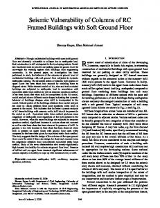
Figure 1:
Schematic diagram for test set-up.
a) Control Specimen CR1 during testing Figure 2:
Axial load testing and failure of control specimen CR1.
a) CR6 during testing Figure 3:
b) Failure of CR1
b) Failure of CR6
Lateral cyclic load testing and failure of specimen CS7.
Group II columns were cast integrally with a 1000×400×400 mm footing for square columns and a 1200×400×400 mm footing for rectangular columns. The footing had six bars of diameter 12 mm as top and bottom reinforcement with WIT Transactions on The Built Environment, Vol 85, © 2006 WIT Press www.witpress.com, ISSN 1743-3509 (on-line)
High Performance Structures and Materials III
423
stirrups 10 mm diameter spaced at 10 cm. The footing dimensions and reinforcement were chosen such that its deformations would not affect the measurements in the test zone. All columns of Group II were tested under constant axial load and increasing cyclic load to failure with columns CS4 and CR4 used as reference. FRP wrapping of columns was applied within the potential plastic hinge zone of the column for a length of 750 mm from the footing top face. Columns CS5 and CR5 were wrapped by one layer of GFRP, Columns CS6 and CR6 were strengthened by one layer of CFRP, and Columns CS7 and CR7 were wrapped by two layers of CFRP. The installation of the FRP jacket necessitates surface treatment. Sandpaper and sand blasting were used for concrete surface preparation before applying the epoxy resin used for installing the FRP wrapping. The sharp corners of the rectangular columns were rounded to avoid premature failure of the jacket due to stress concentration at sharp corners. Epoxy was applied uniformly on the entire face of the concrete column as well as on the FRP laminate. The fabrics were then compressed to the concrete surface with a roller. The thickness of the epoxy layer was controlled to be about 1.2 mm. The specimens were treated at room temperature for at least 24 hours before testing. Group I specimens were instrumented with 2 LVDT’s at the mid-height to measure out of plane deformation. Strain gauges were attached to longitudinal reinforcements and the stirrups at the column mid-height to measure longitudinal and transverse strain during loading. Surface strain gauges were also mounted to the concrete surface and to the FRP jacket. Those measurements will be used for verification of the detailed numerical models developed in the second phase of this research. As for Group II specimens, LVDT’s are used to measure the lateral displacement at the top and mid-height of the columns during testing. Furthermore, strain gauges are used to measure vertical and lateral strain on reinforcement and concrete and FRP surfaces near the column base. The measured load, displacements, and strains at the various locations were fed into the data acquisition system and recorded for further processing and analysis. Figure 1 shows schematic diagrams of the test set-up for Group I and Group II specimens. Figures 2 and 3 show sample specimens during testing and at failure. Avreage stress at failure (N/mm2)
60
50
40
CR2 CS1 CS2 CS3
30
20
10
0 0
0.5
1
1.5
2
2.5
Strain measured on longitudinal steel RFT(%)
Figure 4:
Variation of axial strain with axial stress for square columns.
WIT Transactions on The Built Environment, Vol 85, © 2006 WIT Press www.witpress.com, ISSN 1743-3509 (on-line)
424 High Performance Structures and Materials III
Avreage stress at failure (N/mm2)
60
50
40
CR2 CS1 CS2 CS3
30
20
10
0 0
0.5
1
1.5
2
2.5
Transverse strain measured on stirrups (%)
Figure 5:
Variation of transverse strain with axial stress for square columns. Avreage stress at failure (N/mm2)
60 CR1 CR2 CR3 (CR3)" (CR1)" (CR2)"
50 40 30 20 10 0 0
Figure 6:
0.5
1
1.5
2
2.5
Strain measured on longitudinal steel RFT (%)
Variation of axial strain with axial stress for rectangular columns.
Avreage stress at failure (N/mm2)
60 50 CR1 (CR1)
40
(CR2)" CR2 CR3 (CR3)"
30 20 10 0 0
0.5
1
1.5
2
2.5
Transverse strain measured on stirrups (%)
Figure 7:
Variation of transverse strain with axial stress for rectangular columns.
WIT Transactions on The Built Environment, Vol 85, © 2006 WIT Press www.witpress.com, ISSN 1743-3509 (on-line)
High Performance Structures and Materials III
3
425
Analysis of test results
Group I specimens are tested under increasing axial load to failure. The square column control specimen formed inclined cracks at an average stress of 30.2 N/mm2 followed by fast progressive failure in the form of falling off the concrete cover and buckling of longitudinal reinforcement. As for specimen CS2, and CS3, the confinement provided by the CFRP jacket delayed the failure to higher stresses values, 48.2 N/mm2 for CS2 and 48.9 N/mm2 for CS3. At failure the CFRP jacket was ruptured due to hoop tensile stresses after which buckling of steel longitudinal bars occurred. The rectangular specimens showed similar behaviour up to failure except that the effect of confinement due to the CFRP jacket was less pronounced. Figures 4–7 show the variation of axial strain and lateral strain with axial stress for square and rectangular column specimens respectively. Figure 8 compares the average axial stress at failure for axially loaded specimens. FRP confinement creases the ultimate capacity of axially loaded square columns by approximately 50%. The confinement effect was less pronounced for rectangular columns where the increase in the ultimate capacity was about 21%. Transferring square column to circular one slightly increase the average failure stress by 1.5%, however the overall load capacity of the column is increased by 5.2% from 193 kN to 203 kN due to increasing the cross section.
2
Average stress at failure (N/mm )
60
48.25 N/mm2
50
48.88 N/mm2
38.875 N/mm2
40
35.625 N/mm2 30.75 N/mm2
30.2 N/mm2 30
20
10
0
CS1
Figure 8:
CS2
CS3
CR1
CR2
CR3
Average axial stress at failure for axially loaded columns.
Group II specimens were tested under constant axial load (30% of the axial load capacity) and increasing cyclic load to failure. Figure 9 shows the loaddisplacement hysteresis loops for specimen CR6 during testing. All specimens in this group showed similar behaviour. As load increased cracking started first at the base, and then more cracks started to develop within approximately 450 mm from the base. With further increasing load, crack opened and concrete in compression crushed forming plastic hinge. Figure 10 shows the envelope for lateral load variation with lateral displacement for square specimens. The variation of lateral load with strain measured on steel stirrups for square specimens is displayed in Figure 11. The load-displacement envelope for rectangular columns is shown in Figure 12. The ultimate lateral load increased by 11%, 22%, and 44% for square column wrapped by GFRP, CFRP and two WIT Transactions on The Built Environment, Vol 85, © 2006 WIT Press www.witpress.com, ISSN 1743-3509 (on-line)
426 High Performance Structures and Materials III CFRP layers, respectively. Similar improvements were observed for rectangular columns where lateral load increased by 12.5%, 25%, and 33.3% for rectangular column wrapped by GFRP, CFRP and two CFRP layers, respectively. Figure 13 compares the lateral load capacity for cyclically loaded columns. 400 300
Lateral load (kN)
200 100 0 -40
-30
-20
-10
0
10
20
30
40
-100 -200 -300 -400
Displacement (mm)
Figure 9:
Load-displacement hysteresis loops for specimen CR6. 150
Lateral load (kN)
100
CS4 CS5 CS6 CS7
50
0 -50
-40
-30
-20
-10
0
10
20
30
40
50
-50
-100
-150
Lateral displacement (mm)
Figure 10:
Lateral load vs. lateral displacement envelop for square columns. 150
Lateral load (kN)
100
CS4 CS5 CS6 CS7
50
0 0
0.5
1
1.5
2
2.5
3
3.5
4
-50
-100
-150
Transverse strain on stirrups (%)
Figure 11: Lateral load vs. lateral strain on steel stirrups for square columns. WIT Transactions on The Built Environment, Vol 85, © 2006 WIT Press www.witpress.com, ISSN 1743-3509 (on-line)
High Performance Structures and Materials III
427
400 300
CR4 CR5 CR6 CR7
Lateral load (kN)
200 100 0 -40
-30
-20
-10
0
10
20
30
40
-100 -200 -300 -400
Lateral displacement (mm)
Figure 12: Lateral load vs. lateral displacement envelope for rectangular columns. 350 300 kN
Maximum lateral load (kN)
300
320 kN
270 kN 240 kN
250
200 130 kN
150
100
90 kN
100 kN
110 kN
50
0
CS4
CS5
CS6
CS7
CR4
CR5
CR6
CR7
Figure 13: Ultimate lateral load for cyclic loaded specimens.
4 Summary and conclusions The performance of fourteen RC square and rectangular columns strengthened using FRP wrapping jacket under axial loading and increasing lateral cyclic loading was experimentally evaluated in this paper. The loads, displacements and strains during testing were recorded for further numerical study. It was found that strengthening RC columns using FRP wrapping is much more efficient in square columns than in rectangular columns. Failure stresses increased due to FRP wrapping by 50% in square columns and 21% in rectangular columns. Transferring square columns to circular columns to improve FRP confinement increases the ultimate stress by only 1.5%. Group II columns subjected to combined axial and lateral loads were wrapped with FRP in the plastic hinge zone. FRP wrapping delayed concrete cracking, and increase ductility. The rupture of the FRP wrap occurs gradually with increasing load giving more warning before failure. The ultimate lateral load is increased by 11%, 22%, and 44% for square column wrapped by GFRP, WIT Transactions on The Built Environment, Vol 85, © 2006 WIT Press www.witpress.com, ISSN 1743-3509 (on-line)
428 High Performance Structures and Materials III CFRP and two layers of CFRP respectively. Similar improvements in the lateral load capacity were observed for rectangular columns (12.5%, 25%, and 33.3%).
References [1] Lehman, D.E., Gookin, S.E., Nacamuli, A.M. & Moehle, J.P, Repair of earthquake-damaged bridge columns. ACI Structural journal, 98(2), pp. 233-242, 2001. [2] Mosallam, A.S. (ed.). Innovative System for Seismic Repair and Rehabilitation of Structures – Design and Application, Proc. (SRRS2), Technomic Publishing co., Inc., 2000. [3] Tan, K.H. (ed.). Fibre-Reinforced Polymer Reinforcement for Concrete Structures, Proc. of the Sixth International Symposium on FRP Reinforcement for Concrete Structures, Singapore, 8-10 July, 2003. [4] Fam, A.Z. & Rizkalla, S.H., Confinement model for axially loaded concrete confined by circular fiber-reinforced polymer tubes. ACI Structural journal, 98(4), pp. 451-461, 2001. [5] Wang, Y.C. & Restrepo, J.I., Investigation of concentrically loaded reinforced concrete columns confined with glass fibre-reinforced polymer jackets. ACI Structural journal, 98(3), pp. 377-385, 2001. [6] Chaallal, O. & Shahawy, M., Performance of fiber-reinforced polymerwrapped reinforcement concrete column under combined axial-flexural loading. ACI Structural journal, 97(4), pp. 659-668, 2000. [7] Mahmoud, Kh., Fouad, E., Ramadan, M.O. & Abd-Elalim, A., Behaviour of axially loaded square RC column confined with sandwich FRP wraps. Proc. International Conference: Future Vision and Challenges for Urban Development, Paper SG96F, Cairo, 20-22 December 2004. [8] Allam, H.M., Strengthening of square columns by a New Technique. Proc. International Conference: Future Vision and Challenges for Urban Development, paper SG167F, Cairo, 20-22 December 2004. [9] Haroun, M. A. & Elsanadedy, H.M., Seismic retrofit of shear-deficient reinforced concrete bridge columns by advanced composite jackets. Proc. Structural Composite for Infrastructure Applications, Aswan, Egypt, 2002. [10] Haroun, M.A., Mosallam, A.S., Feng, M.Q. & Elsanadedy, H.M., Experimental Investigation of Seismic Repair and Retrofit of bridge columns by composite jackets. Journal of Reinforced Plastics and Composites, 22(14), pp. 1243-1268, 2003. [11] Hosny A., Shahin, H. Abdelrahman, A., & El-Afandy, T., Uniaxial tests on rectangular columns strengthened with CFRP. Proc. Structural Composite for Infrastructure Applications, Aswan, Egypt, 17-20 Dec., 2002.
WIT Transactions on The Built Environment, Vol 85, © 2006 WIT Press www.witpress.com, ISSN 1743-3509 (on-line)