dynamic thermal management techniques are essential. In this paper, we present the design of a system that monitors the tem- peratures at various locations on ...
Monitoring Temperature in FPGA based SoCs
Siva Velusamy† , Wei Huang‡ , John Lach‡ , Kevin Skadron† Departments of Computer Science† , and Electrical and Computer Engineering‡ University of Virginia. {siva, skadron}@cs.virginia.edu, {whuang, jlach}@virginia.edu CS Technical Report CS-2004-39 Abstract FPGA logic densities continue to increase at a tremendous rate. This has had the undesired consequence of increased power density, which manifests itself as higher on-die temperatures and local hotspots. Sophisticated packaging techniques have become essential to maintain the health of the chip. In addition to static techniques to reduce the temperature, dynamic thermal management techniques are essential. In this paper, we present the design of a system that monitors the temperatures at various locations on the FPGA. This system is composed of a controller interfacing to an array of temperature sensors that are implemented on the FPGA fabric. We discuss the issues involved in designing and interfacing to the sensors. We compare the sensor readings with values obtained from HotSpot, an architectural level thermal modeling tool. Finally we show how such a system can be used in two micro-architectural studies - determining the effect the splitting one high power density unit into components that can be spread over the chip, and analyzing the response of a system to thermal emergencies.
1
Introduction
Continual improvements in process technology has enabled IC designers to increase logic density. However, this increase in logic density, coupled with the increased frequency of operation has resulted in an exponential increase in power density. According to ITRS [1] microprocessor power density is projected to reach 100 W/cm2 beyond the 50nm technology nodes. This exponentially increasing power density manifests itself as heat which has to be continually removed from the die to ensure reliable operation. Another factor complicating the issue is the presence of local hotspots, which arise due to varying levels of power dissipation across the chip. Increased junction temperature and the presence of local hotspots has many deleterious effects. Increased temperature decreases the transistor switching speed, thereby directly reducing performance Leakage current increases exponentially with temperature, causing a positive feedback loop between leakage power and temperature [2]. Finally, reliability of a device decreases exponentially with increased operating temperature, as observed from the Arrhenius equation M T F=M T F0 exp(Ea /kb T ), where T is the operating temperature. 1
Sophisticated packaging techniques are now employed to reduce the effect of increased temperatures. A spectrum of techniques from heatspreaders, heatsinks to active cooling are employed to spread the heat generated more efficiently. In high-performance microprocessors packaging costs rise by $1 to $3 per Watt of power dissipated [3]. To avoid designing packages for the worst case operating condition, current generation microprocessors employ some form of dynamic thermal management (DTM) e.g, clock gating, dynamic voltage scaling. The DTM technique is employed when operating temperature exceeds a certain predefined value. As FPGA based System-on-a-Chips (SoCs) are getting more popular, many of the issues regarding temperature need to be tackled. SoCs are employed in a wide variety of operating conditions, and as a result, a single packaging solution will be necessarily inefficient. Hence, implementing some form of dynamic thermal management becomes critical for cost effectiveness and ensuring reliability of operation. In this paper, we present the design of a system that continually monitors the temperature levels at various locations on the die, and activates a thermal response when an thermal emergency is detected. This system comprises of an array of temperature sensors implemented on the FPGA fabric. The main contributions of this paper are as follows: • We describe the overall design of a system capable of implementing DTM in FPGA based SoCs. • We discuss the issues involved in the design of a temperature sensor that can be implemented on an FPGA. • We compare the sensor temperatures to values obtained from HotSpot [6] – an architectural level thermal simulator. • We identify the spatial granularity at which thermal phenomena can arise in FPGA based designs. The reminder of the paper is organized as follows. In Section 2, we present the overall design of the system, followed by a detailed description of a ringoscillator based temperature sensor. We describe issues involved in calibrating the sensor, and in interfacing to the sensor. In Section 3 we describe the changes made to HotSpot and compare the temperatures predicted by HotSpot with the temperatures obtained from the sensors.In Section 4 we identify the spatial granularity at which thermal variations can occur. Section 5 presents the implementation of a DTM scheme and Section 6 conludes the paper, and provides suggestions for future work.
2
Design
We implemented our design on a Xilinx Virtex-2 Pro (XC2VP7) FPGA present in the Insight Memec board [4, 5]. However, the techniques used are equally applicable across other FPGA based systems with minor modifications. 2
2.1
System
A typical SoC contains a processor and peripherals implemented on the FPGA. This can be augmented to monitor temperature by adding the following components: • An array of temperature sensors. Section 2.2 describes how temperature sensors can be implemented on the FPGA fabric. • A controller that monitors the temperatures readings from the different sensors and activates the DTM mechanism when appropriate. The controller is described in Section 2.3. For experimental purposes, the FPGA core was powered by an Agilent E3631A DC power supply. This lets us measure the power consumed by the logic on the FPGA core.
2.2
Temperature Sensor
Our temperature sensor is based on the design proposed by [7, 8]. This utilizes the fact that the transistor switching speed is directly proportional to the temperature. In such a sensor, a ring oscillator is implemented on the die - the FPGA fabric in this instance, and the frequency of oscillation is used as a proxy for the temperature. 2.2.1
Design
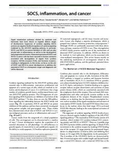
A ring oscillator is a sequence of odd number of inverters connected in series to form a chain. This can be implemented on the FPGA by configuring the LookUp Tables (LUTs) as inverters and chaining them together. The schematic of such a sensor is shown in Figure 1.
RING ENABLE
CLK
CAPTURE COUNTER
Figure 1: Temperature sensor schematic. Frequency of oscillation is directly proportional to the junction temperature
3
On an FPGA, each inverter can be implemented by programming a single LUT to perform the NOT function on its input. The inputs and outputs are then connected by programming the interconnect. The number of inverters required in the chain is dependent solely on the speed of the logic and routing. The longer the inverter chain, the lower the frequency. A longer inverter chain also consumes less power since the number of transitions is lower. In our experiments we use a ring oscillator composed of 7 inverters. There are many different paths by which one LUT can be connected to another, and each path has a different delay. By default, the place and route tools do not assign the same path between instances. There is no good way to constrain the routing. To obtain identical delays (and hence identical base frequencies) between multiple instances of the sensor, we took the following approach: Using FPGA editor [9], select one instance of the sensor, and use the Directed Routing option to fix the routing of that sensor. This results in constraints being set for the interconnects for this sensor instance. The same constraints are then manually copied over for all sensor instances in the design. An alternative method to obtain predictable delays is to use the carry chain present in the FPGA. A carry chain connects the outpus the each LUT with the one above it. There is a single carry chain that propagates upwards in each slice column. Hence there are no degrees of freedom available for the place and route tool, thereby automatically constraining the routing. However, we found that the delays on the carry chain are much smaller that regular routing. Hence to obtain a frequency of oscillation that we can measure, it became necessary to artificially lengthen the carry chain. We did not use this design since the size of the sensor was bigger due to the carry chain length. The output of the ring oscillator chain is then buffered and used as a clock input to the Capture Counter. This counter reading directly specifies the oscillation frequency of the ring oscillator. Each sensor was found to consume approximately 1 mW of power which is less than 1% of the power consumed by the FPGA core. To keep the power consumed by the sensors low, they are enabled only for a certain amout of time, which is the sum of Enable Time and Capture Time. During Enable Time, the ring oscillator is switched on, and the Capture counter is reset. This is to allow the oscillator to stabilize. Subsequently the counter is enabled for Capture Time interval. Experimentally, we determined that a Enable Time of 1024 cycles and a Capture Time of 8192 cycles provides a good tradeoff between power consumed and accuracy. The Capture Counter has enough precision to store a change of less than 0.1 degree Celsius. 2.2.2
Calibration
To obtain the frequency response of the ring oscillators, we placed the FPGA test board inside a temperature controlled oven, and measured the output frequencies at various temperatures. Figure 2 plots the frequencies over a temperature range of 25 ◦ C to 65 ◦ C, for 6 different sensors placed at different locations on 4
the die. 156
Frequency (Mhz)
154 152 150 148 146 144 142 140 25
35
45
55
65
Temperature (C)
Figure 2: Variation of oscillator output frequency with temperature As seen from Figure 2, the output frequency varies linearly with increase in temperature. The slope of the line, equal to 380 kHz/◦ C, gives us the effective change in sensor frequency corresponding to any temperature change. The frequency of operation also depends on the source voltage. This is plotted in Figure 3. 158
Frequency (Mhz)
157 156 155 154 153 152 151 1.4
1.45
1.5
1.55
1.6
Voltage (V)
Figure 3: Variation of oscillator output frequency with core voltage Ideally, we should have the operation of the sensor dependent on only one factor. In this case we find that the sensor frequency variations due to voltage are significant enough to affect the frequency response. Hence this type of sensor cannot be used in the presence of varying voltages, or with boards that have not been designed for low voltage and ground bounce.
2.3
Controller
The controller determines when the sensors have to be enabled, and performs the steps required to enable the sensors and read back the values from the 5
sensors. Once the controller knows the temperatures at various locations on the die, it can decide to implement some thermal management technique if needed.
S4
Bus
S3
PowerPC
S2
S1
S5
Figure 4: Block level view of the components in the design In our implementation, we use the embedded PowerPC processor present in the Virtex-2 Pro device as a controller. Figure 4 shows the high level overview of the base setup necessary to measure and control temperatures. The figure shows 5 sensors S1 through S5 connected to the controller (PowerPC) through a bus. We use the On-chip Peripheral Bus (OPB) bus [10] to connect to the sensors. The OPB bus connects to the processor through a bridge. Each of the sensors interface to the bus using the General Purpose I/O (GPIO) core [11]. This provides a simple interface for the processor to set or reset signals directly in the sensor. To obtain a reading from a sensor, the controller does the following steps: • Reset the sensor. This resets all the counters present in the sensor. • Re-enable the sensor. This enables the ring oscillator for Enable Time + Capture Time. The Capture Counter is enabled after Enable time has elapsed. Both the ring oscillator and the counter is disabled after capture time. • Read back the capture counter value from the sensor. • Map the frequency value from the counter to temperature.
6
3
Comparison with HotSpot
In this section, we compare the temperatures obtained using simulation with HotSpot – an architectural level thermal simulator [6]. HotSpot has been validated against a test chip and against finite element simulation [12]. HotSpot takes in a number of parameters that affect the thermal properties of the system. These include the properties of the Silicon, properties of the thermal interface material, heat spreader and the heat sink. Table 1 lists all the configuration changes we made to HotSpot to reflect the setup of the FPGA based system used in the experiments. Parameter t chip r convec s sink t sink t interface die size
Value 0.8 mm 13.9 K/W 0.011 m 0.1 mm 0.025 mm 6.57 mm x 7.04 mm
Comments Thickness of the chip Convection resistance, from [13] Heatsink width, set to simulate no heatsink Heatsink thickness, set to simulate no heatsink Thickness of interface material Scaled to 130 nm technology from the value in [15]
Table 1: HotSpot parameters to match the test system Using the floorplan shown in Figure 5, we compare the outputs obtained using HotSpot with the specified parameters and the values obtained from the sensors. The results are in Table 2.
Figure 5: Floorplan used for comparison with HotSpot We see that on average the difference in temperatures predicted by HotSpot and those obtained from the sensors differs only by less than 0.2 ◦ C. 7
Unit blank1 left ppc bott ppc ppc mb blank2
Power (mW) 0.1 75 75 45 313 0.1
Sensor Temperature 3.4 3.5 3.4 3.5 4.1 3.4
HotSpot temperature 3.37 3.69 3.67 3.66 3.96 3.38
Table 2: Temperature readings obtained from HotSpot and FPGA sensors
4
Granularity of Temperature Variations
Power density levels across a chip vary significantly. This is because units like the register file and the issue queues in a superscalar processor, are small in area, but are accessed frequently. This results in local hotspots across the chip. In this section, we find out experimentally if local hotspots can be reduced by spreading the high power density units over a broader area. We show that small hotspots can be mitigated if they are split and spread among other cold units. Figure 6 shows the four different configurations for the placement of a single high power density unit. In the first configuration, the block is packed together within a narrow region. In the remaining three configurations, the block is split into three sub-blocks, and spread out over varying distances. In all cases, the total power consumed by the blocks is identical, and the power density across each block is also identical. We repeat the same experiment varying the size of the block. The results are tabulated in Tables 3 and 4. block size 2 slices 4 slices 8 slices
Config I 2.81 4.15 6.82
Config II 2.71 3.40 6.86
Config III 2.66 3.06 6.62
Config IV 2.58 3.02 6.9
Table 3: Average temperatures across different configurations of placing the hot unit block size 2 slices 4 slices 8 slices
Config I 3.02 4.46 7.21
Config II 2.87 3.67 7.24
Config III 2.81 3.26 6.96
Config IV 2.71 3.21 7.1
Table 4: Maximum temperatures across different configurations of placing the hot unit
8
I
II
III
IV
Figure 6: Placement of 3 hot units: (I) - close, (II) - medium, (III) - large, (IV) - distant. The 3 units are shown bounded with a black box. In Tables 3 and 4 the temperature levels are different since the total power consumed is different. However within each row, the total power density is maintained constant. We can note that when the hot unit is of size 12 slices, splitting it and spreading it around into 3 blocks of size 4 slices each contributes to a much higher temperature reduction, than if the block size is 8 slices. When the sub block size is just 2 slices, there are no significant hotspots that can benefit from spreading the heat around.
5
Dynamic Thermal Management
Processor packaging was typically designed for the worst case power density. However this worst case does not occur so often, and hence it is inefficient to design packages with worst case power density in mind. In recent year, Dynamic Thermal Management (DTM) has been proposed as the solution [14, 6]. With DTM, packages are designed for the typical case, and if the worst case scenario should arise, it is handled by slowing down the processor and thereby cooling it 9
through one of the many DTM mechanisms. Many of the same problems are also applicable to FPGA based SoC’s. Another factor complicating the issue is that the power density levels in an FPGA vary widely over designs. As a result, we propose that such DTM schemes will also help FPGA based designs. Here we show how a simple DTM mechanism – clock gating can be implemented. With clock gating, whenever the temperature of the chip raises beyond a specified temperature called the trigger point, the clock to the design is gated for a specific interval. After the chip cools down, the clock is re-enabled, and the design continues operating. Thus we trade off performance for reduced temperature of operation.
Figure 7: FPGA temperature without clock gating
Figure 8: FPGA temperature with clock gating employed Figures 7 and 8 show the on chip temperature as obtained from six different sensors. In Figure 7, no DTM scheme is employed and the temperature is allowed to rise. In the second case, the design is clock gated if the temperature exceeds 3.5 ◦ C. Thus the temperature remains below the thermal threshold. 10
Clock gating is implemented by the controller. When the controller detects that the on-die temperature is greater than the trigger threshold, it disables the clock to the MicroBlaze which is the hottest unit in this system. This clock gating is implemented via the BUFGCE – the buffered clock gate with enable element present in the FPGA device.
6
Conclusion
In this paper, we have developed a system capable of performing thermal management on FPGAs. The system is configurable such that the sensors can be placed anywhere on the system, and be easily accessed by the controller. We have shown that the temperatures obtained from the sensors correlate well with temperatures predicted by HotSpot. We have also shown that local hotspots can be avoided by splitting up the hotspot region into multiple smaller units and interspersing them along with cooler units.
References [1] The International Technology Roadmap For Semiconductors (ITRS), 2003. [2] S. Heo, K. Barr and K. Asanovic, Reducing Power density through Activity Migration, In Proc. of ISLPED, Aug 2003. [3] S. Borkar, Design challenges of Technology Scaling, In IEEE Micro, Jul-Aug 1999. [4] Insight Memec board documentation, http://www.insight.memec.com [5] Xilinx Virtex-2 Pro User Guide, http://direct.xilinx.com/bvdocs/publications/ds083.pdf [6] K. Skadron, M. R. Stan, W. Huang, S. Velusamy, K. Sankaranarayanan, and D. Tarjan. Temperature-aware microarchitecture. In Proc. ISCA-30, June 2003. [7] S. Lopez-Buedo and E.Boemo, Making Visible the Thermal Behavior of Embedded Microprocessors on FPGAs. A Progress Report. In Proc. FPGA ’04, Feb 2004. [8] S. Lopez-Buedo, P. Pernas and E. Boemo, Thermal Testing on Reconfigurable Computers, In Proc. of IEEE Design and Test of Computers, Jan-Mar 2000. 11
[9] Xilinx FPGA Editor, http://toolbox.xilinx.com/docsan/xilinx6/books/manuals.pdf [10] IBM On Chip Peripheral Bus (OPB), http://www-03.ibm.com/chips/products/coreconnect/ [11] OPB GPIO peripheral core, http://www.xilinx.com/ipcenter/processor central/coreconnect/coreconnect opb.htm [12] Wei Huang, Mircea Stan, Kevin Skadron, Karthik Sankaranarayanan and Shougata Ghosh Compact Thermal Modeling for Temperature-Aware Design, In Proc. of DAC, June 2004. [13] Device Packaging and Thermal Characterisitcs, http://direct.xilinx.com/bvdocs/userguides/ug112.pdf [14] D. Brooks and M. Martonosi, Dynamic Thermal Management for HighPerformance Microprocessors, In Proc. of HPCA, 2001. [15] C. Yui, G. Swift and C. Carmichael, Single Event Susceptibility Testing of the Xilinx Virtex II FPGA, In Proc. of MAPLD, 2001.
12