1 a schematic diagram of the fabricated device is shown, and in the inset to Fig. 2 we show the layer structure of the MBE grown GaAs/(AIGa)As wafer used.
-
Although broader pulses reduce the soliton self-frequency shift, we still prefer to have 70uJ7in 1 because of cascadability and for improved contrast in the crosscorrelation.
References
c. E., and MILLER, D. A. 8.: 'Low-energy ultrafast fiber soliton logic gates', Opt. Lett., 1990, 15,,pp.909-911 2 GORWN, I. P . : 'Theory of the soliton self-frequencyshift', Opt. Lett., 1986,11, pp. 662464 3 ISLAM, M. N., SOCCOLICH, c. E., GORDON, J. P., and PAEK, U. c.: 'Soliton intensity-dependent polarization rotation', Opt. Lett., 1990,15, pp. 21-23 1
ISLAM, M. N., SOCCOLICH,
MONOLITHIC InP-BASED GRATING SPECTROMETER FOR WAVELENGTH-DIVISION MULTIPLEXED SYSTEMS AT 1.5pm -1
0
1
2
3
4
5
6
time.ps
7
1529121
Indexing t e r m : Spectrometry, Optical communication
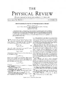
Fig. 2B Autocorrelation of control pulse emergingfrom inuerter
A monolithic InP-based grating spectrometer for use in wavelength-division multiplexed systems at 1 3 p n is reported. The spectrometer uses a single etched reflective focusing diffraction grating and resolves >50 channels at 1 nm spacing with a -0.3nm channel width and at least 19dB channel isolation. Operation is essentially of the state of the input polarisation.
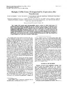
Despite the adiabatic broadening, the control pulse can be recompressed at the output by introducing a third fibre. From perturbation theory we know that the asymptotic value of the soliton is (1 + 2 4 sech [(l + 2a)tl when we start with an input electric field (1 + a ) sech (t). We can recompress an a < 0 pulse either by amplifying the output and then coupling into another fibre or by going straight into another fibre with a lower soliton energy. If the output from the long fibre enters another fibre with normalised amplitude (1 + GXI Za), where (1 + 2G) = (1 + 2a)-', then the pulse shrinks back to its original pulse width in a few soliton periods. For example, we have done computer simulations for -0.25 < a < -0.2 and find that E ~ ~ , / Treturns , ~ to 1 within 2 to 2.5 soliti 1 periods.
Wavelength-division multiplexed (WDM) systems are currently being investigated for optical data transmission in telecommunications and computer local area networks.' Compact hybrid demultiplexers have been reported for use in such systems.' However, integration offers the advantages of small size, reliability, and a low unit cost, and implementation in semiconductor material allows monolithic integration with sourcesJ and detectors.4 An integrated demultiplexer fabricated in planar InP/ InGaAsP waveguide material employing a high order transmission grating and concave mirrors has been r e p ~ r t e d . ~ Recently, a reflection grating demultiplexer demonstrating 20 channels with a 4nm wavelength spacing was described.6 We report a monolithic InP-based single grating spectrometer which resolves > 50 wavelength channels at a 1nm spacing with 0.3 nm channel width and better than 19 dB channel isolation. The spectrometer may be operated so that it is completely polarisation-insensitive. This is the best spectral performance reported to-date for a multichannel semiconductor-based wavelength demultiplexer. Introduction:
+
20
P Q
-
(0
't VI
-:
1 0 3 L
VI
Design and fabrication: The integrated spectrometer was formed in a InP/InGaAsP/InP planar waveguide.' Based on a Rowland circle construction,8 it used a single vertical-walled reflection focusing diffraction grating, implemented in a Littrow-type configuration, to perform the wavelength dispersion. Identical, equally spaced, single moded ridge waveguides formed the input and output ports. A schematic diagram of the device is shown in Fig. 1. The spectrometer was designed to operate around 1.5pm, with a channel spacing of 1nm. The grating had a d-spacing of 5.lpm, operated in 18th order, and was blazed for retroreflective diffraction at 1.51pm. The waveguides had 9 p m wide ridges and were spaced at 20pm. The optical body of the spectrometer was 11mm x 1.6". A double heterostructure guide, InP/l.l pm InGaAsP (,Igap= l.Opm)/0.6pm
00
0 Fig. 3 Spectral shift 6v normalised to the original spectral width AV,, (right axis) and broadening of control pulse T ~ ~ (left J T axis) ~ ~ in 2 k m long polarisation maintainingfibre asfunction of input power P J P ,
In summary, we demonstrate a soliton dragging inverter based on time shift keying with a switching energy of only 1 pJ and a control energy of 28pJ. Although the pulse width is broadened to avoid SSFS in the 2 km fibre, the output can be recompressed in a short segment of another fibre.
-
I t
I
Acknowledgment: C.-J. Chen's work is supported by the US
Department of Energy. M. N. ISLAM C. E. SOCCOLICH C.-J. CHEN K. S . KIM J. R. SIMPSON U. C. PAEK AT&T Bell Laboratories Holmdel, New Jersey 07733, USA
132 -
7th November I990
I t
1
-
(564/11
Fig. 1 Schematic diagram of integrated spectrometer ELECTRONICS LETTERS
1
12"
-
~
17th January 1 9 9 1 ~
Vol. 27 N o . 2
InP, was chosen t o minimise the polarisation sensitivity of the device. The waveguide structure was grown by low-pressure OMCVD on semi-insulating InP. A single photolithographic stage defined both the grating and the input/output waveguides, which were then dry etched using the photoresist mask. Chemically assisted ion beam etching (CAIBE)’ with Xe+ and a reactive flux of Cl, was used. First, the grating and guides were etched to a depth of -0.25pm, to define the waveguide ridges. The guides were then shielded from the ion beam and the grating was etched further, to a total depth of 2.3pm. The resulting grating wall was < V from the vertical; it was not reflection coated. The chip was then cleaved, and a single layer antireflection coating was deposited on the input/ output guide facet. The waveguides were -0.5-1.5 mm long.
intervals over the central portion of the range, with a small amount of second order dispersion apparent in the wings; in all, 52 modes are recorded from 1.4825pm to 1.5314pm, a range of nominally 49 nm. This weak nonlinearity, however, is purely geometric in origin and may be corrected by adjusting the guide spacing.
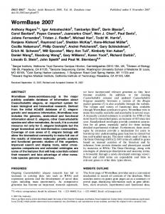
Spectrometer performance: Spectrometer performance was evaluated using an F-centre laser, tunable from 1.48pm t o 1.53pm. A 0.25 NA objective lens was used to focus the light into an input guide. Although this lens did not optimise the in-coupling efficiency, it allowed the emission from a large number of output channels to be examined through the same objective. This emission was beam-split off and focused onto an i.r. vidicon. A calibrated intensity scan from the vidicon allowed output guide mode profiles, channel relative output power, and channel crosstalk to be evaluated. By comparing the output intensities with the intensity of light reflected from the input facet, an estimate for the on-chip loss was made. The waveguide that generated retrodiffraction at 1.500pm was chosen as the input guide. As the incident wavelength was scanned, light was observed from the output guides in sequence; all were single-moded. Fig. 2 is a montage of the near-field images of the input/output guide facet, recorded as the wavelength was tuned progressively from one channel wavelength to the next over a range of 32 output guides, 16 guides on each side of the input; for clarity, only every other output emission is pictured. The central spot is the light reflected from the input beam. Over 50 output channels were recorded, covering the wavelength range of the incident light, 1.480pm-l.530pm. The wavelengths of 52 channels are plotted against channel number in Fig. 3. In this case, the incident light was T M polarised, The output channels are spaced at exactly I n m
Fig. 3A As-recorded near-field profiles of 32 most prominent output channel emissions covered by wavelength range of incident light
-
Output wavelengths, 14904 nm-1521.3nm 2
-B
1
-41 -6
= 1
q -8 O
-10 1480
1490
1530 1510 1520 channel wavelength ,nm
1530
Fig. 38 Output channel powers, normalised to a constant incident light power 35 channels are observed within 3dB of the peak output coupled
power
~-
1485 3 nm
2-1 - 1 1-1
1490 8nm
-
1192 6nm
1487 2nm
Fig. 4 a shows computer-scanned vidicon intensity traces of the light emitted from the 32 most prominent output channels; wavelength range 1490.8nm-1521.3nm. Fig. 4 b is a plot of the channel output powers, over a somewhat larger range, corrected for the nonlinearity of the vidicon and normalised to the incident light power. A spectral range of 35 nm is indicated for operation within -3dB of the peak output power. The power decrease towards the limits of the wavelength range is presumably due to a lower diffraction eficiency, though normalisation to a diminishing and increasingly unstable incident light power made a detailed examination impossible.
1489 2nm
I
1540,
1494 5nm 1496 2nm
,498 3 nm
- 1
1500 0 nm
1502 Onm
1503 8 n m
1505 6nm
. I . I _ I I
1507 Lnm
15098nm 1511 4 nm
1513 3 n m 1515 2 n m
t
input waveguide
1564121
Fig. 2 I6 wavelength demultiplexed outputs Plctures are of every other of 32 outputs, 16 on either side of the
input gude ELECTRONICS LETTERS .-
Tp--
channel number
Fig. 4 Wavelength against output channel number for spectral range of incident light
17th January 1991
~~
An examination of channel output power as a function of wavelength revealed a spectral width of 0-3-0,35nm, full width at half maximum. This high spectral resolution, which agrees with the calculated diffraction-limited value, is testament t o the high quality of the CAIBE etched grating and the excellent uniformity of the OMCVD grown waveguide material. Crosstalk arising from all nearby output channels was measured to be - 19 dB ( 2 dB) and is believed to arise primarily
+
Vol. 27 No. 2
133 ~ - _ _ _ _
from random waveguide to waveguide coupling caused by ridge imperfections. Crosstalk from a channel wavelength far from a guide under examination was < -30dB, at the limits of the measurement sensitivity. In particular, we note that no grating ‘ghosts’ or light from the other diffracted orders were observed. This high channel isolation is a significant improvement on previous device^.^,^ The semiconductor-based spectrometers reported to date5,6 have suffered from a severe polarisation dependence, a change of polarisation giving an output shift equivalent to, or even larger than, the channel spacing. The double heterostructure waveguide structure used here ensures that the spectrometer is only weakly sensitive to the state of the input polarisation. The centre wavelengths of the output channels were found to differ by just 0.23nm for TE and T M polarised incident light (ATE > ,ITM), which is less than the 0.3-0.35nm spectral width of the channel. When the wavelength was tuned midway between the TE and T M centre wavelengths, no polarisation dependence of the output intensity was observed. On-chip losses were estimated at 16dB. This evaluation used a calculated in-coupling loss. As the experimental coupling eficiency may be somewhat poorer, the on-chip losses may in fact be lower. Of this 16dB, 5 6 d B is due to light transmitted through the etched grating, which was not reflection coated, with I-2dB attributable to guide losses. This implies a grating loss of -9 dB. Part will be due to radiation reflected into the substrate and part to light scattered into the other diffraction orders. By improving the verticalness of the grating and/or decreasing the diffraction order, this loss should be reduced. Such investigations are currently in progress.
-
Summary: We have realised an InP-based grating demultiplexer which resolves >50 channels around 1.5pm wavelength at 1 nm spacing, with -0.3 nm resolution, > 19 dB channel isolation, and almost no polarisation sensitivity. The device is expected to find application as a passive element in WDM systems and may be readily integrated with lasers and detectors for the transmission and reception of multiwavelength signals.
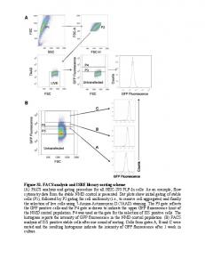
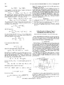
GATED RESONANT TUNNELLING DEVICES Indexing term. Tunnel diodes The fabrication and operation of a 1pm x 1pm gated GaAs/ (AIGa)As resonant tunnelling diode is described. By biasing the gate the l/V characteristic can be varied and hence the negative differentialresistance of the diode can he controlled. Using a wafer with an appropriate doping profile ensures that the maximum depletion due to the gate will occur close to the (AIGa)Astunnel barriers. When a large negative bias is applied to the gate extra structure develops in the IjV characteristic which may be related to the modification of the sub-band structure in the well due to the lateral quantum confinement of electrons hy the gate. The potential of this fabrication techniqueis also discussed for resonant tunnelling and vertical field effect transistors. Recently several groups working on resonant tunnelling diodes (RTDs) have focused on the properties of small diodes with lateral dimensions of order 1pm or less, for applications t o high frequency microwave generation’ and also for the investigation of the effects of lateral quantisation.’ All of this work has been performed on two-terminal devices for which the electrical dimensions are fixed. Here we describe the fabrication of a three terminal device in which the effective crosssection of the RTD may be varied by varying the negative bias V, on a lateral gate. As V, is increased from 0 to 5 V the peak current in the I/V characteristic is reduced by an order of magnitude and additional structure develops which may be related to lateral quantisation of electron states. In Fig. 1 a schematic diagram of the fabricated device is shown, and in the inset to Fig. 2 we show the layer structure of the MBE grown GaAs/(AIGa)As wafer used. On both sides of the tunnelling barriers the n-type doping concentration is varied from 2 x 1016cm-3 to 2 x 10’8cm-3 over several layers, the total thickness of which is approximately 1 pm. A 3.4 nm undoped region separates the A10.,Gao.6As barriers from the doped layers of GaAs. The process steps are now outlined in order (i) a Au/Ge/Ni ohmic contact is formed to the substrate
J. B. D. SOOLE
13th November 1990
A. SCHERER H. P. LEBLANC N. C. ANDREADAKIS
R. BHAT M. A. KOZA Bellcore 331 Newman Springs Road, Red Bank, N J 07701, USA References BRACKETT, c.: ‘Dense wavelength division multiplexing networks: principles and applications’,IEEE J. Se1 Areas in Comm., 1990, 8, pp. 948-964 2 CANNELL, G . J., ROBERTSON, A., and WoRTHINGmN, R . : ‘Practical realization of a high density diode-coupled wavelength demultiplexer’, IEEE J . Se/. Areas in Comm., 1990,s. pp. 1141-1154 3 KIRKBV,P. A . : ‘Multichannel-switchedtransmitters and receiversnew component concepts for broad-hand networks and distrihuted systems’, J. Lightwave Tech., 1990.8, pp. 202-21 1
(ii) Au/Ge/Ni ohmic contacts are formed to the top n+-GaAs layer. These contacts vary in size from l p m square up to 15pm square. The large (z1Opm) features are used for alignment purposes (iii) the sample is reactive ion etched in SiCI, to a depth of 1.3pm. The previously formed ohmic contacts act as a mask (iv) a Au/Pd gate is deposited around the perimeter of the small (1 pm x 1 pm) mesas. At this stage the device closely resembles that shown schematically in Fig. 1, in which the
1
4
SOOLE, 1. B. D., SCHUMACHER, H., ESAGUI, R., LEBLANC, H. P., BHAT, R., and KOZA, M. A . : ‘High-speed metal-semiconductor-metal wave-
guide photodetector on InP’, Appl. Phys. Lett., 1989,55, pp. 2173-
source ohmic
contact
d. ,. ’depleted
2176
5
?I
‘S
depleted
!
region
tunnel barriers
region
GIBBON, M., THOMPSON, G . H. B., CLEMENTS, S. I., MOULE, D. J., ROGERS, c . E., and CURE”, c . G.: ‘Optical performance of integrated
1 . 5 ~grating wavelengthdemultiplexer on InP-based waveguide’, Electron. Lett., 1989, 25, pp. 144-1442 6
CREMER, c . , HEISE, G., MULLER-NAWRATH, R., STOLL. L., VEUHOFF, E., and BAUMEISTER, H.: ‘Grating spectrograph in InGaAsP/InP. Pro-
~~
n ’ substrate
ceedings of ECOC ’90, Amsterdam, 1990, pp. 109-1 12 7
V////////A’///A
SOOLE, J. B. D., SCHERw(, A., LEBLANC, H. P., ANDREADAKIS, N. C., BHAT, R., and KOZA, M. A.: ‘Spectrometer on a chip: an InP-based
grating demultiplexer for WDM applications at 1.5pm’. Proceedings of LEOS ’90, postdeadline paper, Boston, 1990 8 ROWLANV, H. A . : Phil. A4ag., 1882, 13, p. 467 9 SCHERER, A., JEWELL, J. L., LEE, Y. H., HARBISON, J . P., and FIAJKEZ, L. I.: ‘Fabrication of microlasers and microresonator optical switches’, Appl. Phys. Lett., 1989.55, pp. 2724-2726 134
drain ohmic contact
Fig. 1 Schematic diagram of cross-section of gated resonant tunnelling
diode edge of the depletion region generated by the gate The position of the AI, p a , ,As tunnel barriers is denoted by the two closely spaced solid lines halfway between the ohmic contacts - - - -
EL.ECTRONICS LETTERS
17th January 1991 Vol. 27 No. 2