tive to the values of Zk0â1(p) and Zk0 (p) and the exposure times of Zk0â1 and Zk0 ..... According to the scheme in [1], the value of El(p) is com- puted by log(El(p)).
Proceedings of 2010 IEEE 17th International Conference on Image Processing
September 26-29, 2010, Hong Kong
MOVEMENT DETECTION FOR THE SYNTHESIS OF HIGH DYNAMIC RANGE IMAGES Zhengguo Li, Susanto Rahardja, Zijian Zhu, Shoulie Xie and Shiqian Wu Signal Processing Department, Institute for Infocomm Research, 1 Fusionopolis Way, Singapore ABSTRACT In this paper, we propose an intensity mapping function (IMF) based scheme to detect moving objects in a set of low dynamic range (LDR) images with different known exposure times. The objective is to remove ghosting artifacts from the eventual high dynamic range (HDR) image. Our contributions include a bidirectional similarity detection method, an adaptive threshold for movement detection, and an IMF based method for the synthesis of pixels to fill in the regions of moving objects. Experimental results show that the proposed scheme outperforms existing schemes. 1. INTRODUCTION. The most popular approach to produce a high dynamic range (HDR) image is to sequentially capture multiple low dynamic range (LDR) images of the same scene using different exposures [1]. This method is simple even though the total capture time is at least the sum of all exposure times. However, ghosting artifacts can be produced by this method when there are moving objects in the scene [3, 5]. This is not a problem in indoor environments, but often unavoidable for outdoor settings. Typical presence of scenarios are moving people, bus, clouds and trees waving of the wind. To remove ghosting artifacts due to moving objects in a scene, the pixels of all LDR images are required to be properly classified into valid and invalid, and only valid pixels are used to generate the HDR image. A camera response function (CRF) based method was provided in [3, 4]. The predicted value for a pixel in an image is computed by using the CRF, the co-located pixel value in its reference image and their exposure times. The pixel is marked as valid if it is well approximated by the predicted value. Otherwise, it is marked as invalid in an error map. An entropy based method was proposed in [5] by using the feature that local entropy is usually not changed much with respect to the exposure times. The local entropy is computed from the histograms constructed from pixels falling within a window with size 5x5. All pixels with local entropy variation larger than a threshold are marked as invalid in an error map. Although this method is not sensitive to estimation error of CRF, but as realized by the authors, the method is not suitable for a situation when two image regions share the same structure but with different intensity. Another drawback of the methods in [3, 5] is the loss of dynamic range for moving objects in the synthesized HDR image. The movement detection methods in [3, 5] are only used to identify the invalid regions of all images. All these invalid regions are then filled in by pixels from one single LDR image. Since moving objects usually belong to invalid regions, the dynamic range of moving objects in the synthesized HDR image are reduced when their dynamic ranges are inherently high. In this paper, we shall propose a new intensity mapping function (IMF) based scheme to detect moving objects. In contrast to
978-1-4244-7993-1/10/$26.00 ©2010 IEEE
3133
existing methods [3, 5], a middle LDR image, Zk0 , is chosen as the initial reference image. All pixels in Zk0 are marked as valid. Zk0 is the reference image of both Zk0 −1 and Zk0 +1 . The detection starts from Zk0 −1 . The values of IMFs between Zk0 and Zk0 −1 are built up by using their accumulated histograms [2, 7]. They are used to design a bi-directional similarity detection method for justifying whether a pixel, Zk0 −1 (p), is valid. If the similarity between Zk0 −1 (p) and Zk0 (p) is greater than a threshold, Zk0 −1 (p) is marked as valid. Otherwise, it is invalid. The threshold is adaptive to the values of Zk0 −1 (p) and Zk0 (p) and the exposure times of Zk0 −1 and Zk0 . Since the correlation between two successive images is the strongest, the reference image for Zk0 −2 is updated after checking all pixels in Zk0 −1 . All valid pixels in Zk0 −1 are the reference pixels for the co-located pixels in Zk0 −2 . All invalid pixels in Zk0 −1 are first replaced by pixels that are reconstructed by using the IMFs between Zk0 and Zk0 −1 and they then serve as the reference pixels for the co-located pixels in Zk0 −2 . The proposed method can be combined with the method in [1] to form a framework for the synthesis of HDR images. The outputs of our method, i.e., the updated reference images, are simply the inputs of the method in [1]. With the proposed scheme, the regions of moving objects are usually filled in by pixels from more than one image. As a result, the dynamic ranges of moving objects are preserved better by using the proposed method. The rest of this paper is organized as follows. The proposed scheme is given in the following section. Experimental results are provided in Section 3 to show the efficiency of the proposed scheme. Concluding remarks are given in Section 4. 2. THE PROPOSED MOVEMENT DETECTION SCHEME Let Zk,l (p) denote the image intensity of the lth color channel at position p when the kth LDR image is captured, i.e. p is a spatial position, l indexes over color channels of red, green and blue, and k indexes over exposure time Δtk . Such a set of LDR images is known as a Wyckoff set [6, 7]. Let Ek,l (p) be the corresponding irradiance value. The relationship between Ek,l (p) and Zk,l (p) is given as Zk,l (p) = fl (Ek,l (p)Δtk + nq,k,l (p)) + nf,k,l (p),
(1)
where 1 ≤ k ≤ n0 with n0 being the total number of input LDR images, fl (·) is the CRF of color channel l, nq,k,l (p) and nf,k,l (p) are sensor noise and electronics noise, respectively. Contrast to existing schemes [3, 5], an image is selected as the initial reference image for the movement detection. For simplicity, the image is denoted as k0 and its value is set as the middle one. All pixels in Zk0 are marked as valid. For any given position p, the set of valid pixels, Ω(Zk0 (p)), is defined as Ω(Zk0 (p)) = {Zk (p)|pixel Zk (p) and Zk0 (p) are similar}.
ICIP 2010
The set Ω(Zk0 (p)) is determined by using the following intra position pixel criterion: �k are the current image Intra Position Criterion: Zk and Z and its reference image, respectively. Zk (p) is in Ω(Zk0 (p)) if the �k (p) is high, i.e., similarity between pixels Zk (p) and Z �k (p)) > Thrk (p). S(Zk (p), Z
optimization problem: Λl,k,π(k) (z) = arg
(2)
2.2. An Adaptive Threshold for Movement Detection
The detection results are used to initialize a weighting matrix wk and the value of wk (p) is 1 if Zk (p) is valid and 0 otherwise. To reduce the effects of noise, the value of wk (p) is filtered over a window of 3 × 3.
The value of Thrk (p) in Equation (2) is adaptive to the values of �k,l (p), Δtk and Δtπ(k) , and it is computed as Zk,l (p), Z Thrk (p) =
1≤l≤3
2Φk,l (p)Ψk,l (p) + 1
l=1
(6)
ξk (p) = max {α1 + max{�(Φk,l (p)), �(Ψk,l (p))}}�(k, π(k)),
�k (p)) in Equation (2) is given by The function S(Zk (p), Z
3 �
2(1 − ξk (p)) , 1 + (1 − ξk (p))2
where ξk (p) is computed as
2.1. A Bi-directional Similarity Detection Method
�k (p)) = S(Zk (p), Z
{|Hk,l (z)−Hπ(k),l (m)|},
(5) where Λl,k,π(k) (0) = 0, and Λl,k,π(k) (z)(0 ≤ z ≤ 255) is a monotonic increasing function of z. Similarly, the values of Λl,π(k),k (z)(0 ≤ z ≤ 255) can be calculated.
Otherwise, Zk (p) does not belong to Ω(Zk0 (p)).
3 �
min
m∈[Λl,k,π(k) (z−1),255]
,
[Φ2k,l (p) + Ψ2k,l (p)] + 1
l=1
where Φk,l (p) and Ψk,l (p) are constructed by using a bi-directional mapping method as � �k,l (p)); if w(Zk,l (p)) ≤ w(Z �k,l (p)) Λl,π(k),k (Z Φk,l (p) = (3), Zk,l (p); otherwise � �k,l (p)) Λl,k,π(k) (Zk,l (p)); if w(Zk,l (p)) > w(Z (4). Ψk,l (p) = �k,l (p); Z otherwise Here, the weighting function w(z) is defined as [1] � (z + 1)/128; if z ≤ 127 w(z) = , (256 − z)/128; otherwise
the scale factor �(z) and the ratio of two exposure times �(k, π(k)) are defined as � 16 2z ( 13z α2 (1 − 255 ) 255 ) ; if z > 127 �(z) = , 10z 2z (50− 51 )16 ; otherwise α3 (1 − 255 ) � max{Δtk , Δtπ(k) } , �(k, π(k)) = min{Δtk , Δtπ(k) } αi (i = 1, 2, 3) are three constants, their values are usually chosen as 1/8, 1/64 and 1/4, respectively. When there is overlapping between the same moving object in images with different exposure times or the background and moving objects are similar, their values are selected as 1/16, 1/128 and 1/16, respectively. 2.3. An IMF based Method for Filling in Invalid Regions All pixels in the region Cπ(k) are marked as valid while all pixels ¯π(k) are marked as invalid. As the correlation in the region C among two successive images is the strongest, the reference image �k (p) is updated as in the following two cases: Z
�k and its and π(k) corresponds to the exposure time of image Z value is updated as follows: � k + 1; if k < k0 π(k) = . k − 1; if k > k0
1. When |k − k0 | = 1, the reference image is reset as Zk0 (p); 2. When |k − k0 | > 1, the reference image is updated by � ¯π(k) � π(k) (p); if p ∈ C Z �k (p) = . (7) Z Zπ(k) (p); otherwise
Λl,k,π(k) and Λl,π(k),k are two IMFs [2, 7], Λl,k,π(k) maps intensity values in the kth image into its reference image and Λl,π(k),k vice versa. The IMF Λl,k,π(k) (z) is defined as a forward IMF, and the IMF Λl,π(k),k (z) as a backward IMF. It is shown in Equations (3) and (4) that the reference value is constructed as in the follow�k (p) is more reliable, the reference value is computed ing way: If Z �k (p). Otherwise, the reference value is computed by by using Z using Zk (p). We thus name the proposed similarity detection method as a bi-directional method.
Clearly, the valid pixels are adopted to replace their co-located pixels in the reference image for the movement detection of the subsequent image. It is very important to properly select the values � π(k) (p) to fill in C ¯π(k) . In the existing method [3, 5], all of Z invalid regions are filled in by pixels from one single selected image. Subsequently, the dynamic ranges of moving objects will be reduced if the dynamic ranges of moving objects are inherently high. To overcome this, pixels are synthesized to fill in the invalid regions by using the following inter position criterion: �k (p) are the current Inter Position Criterion: Zk (p) and Z image and its reference image, respectively. Assuming that Zk (p) �k (p)) and Ω(Z �k (p� )) respectively, and Zk (p� ) are in the sets Ω(Z
The forward IMF Λl,k,π(k) (z)(0 ≤ z ≤ 255) and the backward IMF Λl,π(k),k (z)(0 ≤ z ≤ 255) are computed by using the accumulated histograms of Zk and Zπ(k) . Let |Θk,l (z)| denote the number of pixels in Zk with the value of Zk,l (p) as z, and and Hk,l (z) the accumulated histograms of Zk . The values of Λl,k,π(k) (z)(0 ≤ z ≤ 255) is obtained by solving the following
3134
Proof. Similar to the proof of Proposition 1, we have
we then have �k,l (p ) =⇒ Zk,l (p) = Zk,l (p ). �k,l (p) = Z Z �
�
log(El (p))
¯π(k) . Suppose that there exists a pixel Consider a pixel p ∈ C � � �π(k),l (p) are equal. Acp ∈ Cπ(k) such that Zπ(k),l (p� ) and Z � π(k),l (p) can be updated cording to the Inter Position Criterion, Z as Zπ(k),l (p� ). Since there may exist many pixels in the region � π(k),l (p) is updated as the value Cπ(k) that satisfy this condition, Z � of Λl,π(π(k)),π(k) (Zπ(k),l (p)) to reduce the possible effect of noise. � π(k) (p) is then synthesized as A pixel Z �π(k),1 (p)), Λ2,π(π(k)),π(k) (Z �π(k),2 (p)), [Λ1,π(π(k)),π(k) (Z T �π(k),3 (p))] , Λ3,π(π(k)),π(k) (Z (8) and it is used to replace the pixel Zπ(k) (p). Obviously, the invalid regions of all images are usually filled in by pixels from more than one image. Since moving objects belong to invalid regions, the proposed method can be applied to preserve the dynamic ranges of moving objects better when their inherent ranges are high. In the remaining part of this section, sufficient condition and necessary condition on the acceptable quality of the final HDR image [7] can be derived by using the set Ω(Zk0 (p)) as follows: Proposition 1. The final synthesized HDR image is acceptable at pixel p if there exists a Zk (p) in the set |Ω(Zk0 (p))| such that the following two Wyckoff signal/noise criteria (9) and (10) are satisfied for all color channel l [6, 7]. fl−1 (Zk,l (p)) w(Zk,l (p))
� �
nq,k,l (p), w(nf,k,l (p)),
=
w(Zk0 ,l (p))(log(fl−1 (Zk0 ,l (p))) − log(Δtk0 )) � � k,l (p)) w(Zk ,l (p)) + w(Z 0
� +
k�=k0
� k,l (p))(log(f −1 (Z � k,l (p))) − log(Δtk )) w(Z l
k�=k0
w(Zk0 ,l (p)) +
�
� k,l (p)) w(Z
.
k�=k0
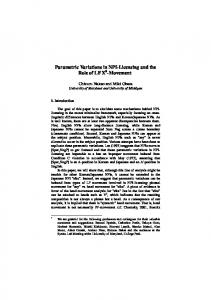
Since Zk0 ,l (p) does not satisfy inequalities (9) and (10), the val� k,l (p)(k �= k0 ) are not reliable. Therefore, the final ues of all Z synthesized HDR image is not acceptable at pixel p. 3. EXPERIMENTAL RESULTS In this section, we verify the proposed movement detection scheme by combining it with the method in [1] to synthesize HDR images as in Fig. 1. Due to the space limitation, the sizes of all images are small. Reader is encouraged to electronically zoom, view and compare the results. First, the proposed bi-directional similarity detection method is compared with the conventional unidirectional method by testing an image sequence that is composed of five images with movement in head and body of a girl. The experimental results are shown in Fig. 2 and it can be seen that the bi-directional method can be used to improve the quality of the synthesized HDR image.
(9) (10)
where the weighting factor w(z) is defined as in [1]. Proof. According to the scheme in [1], the value of El (p) is computed by
Fig. 1. Overall structure on the robust synthesis of HDR images
log(El (p)) � �k,l (p))(log(f −1 (Z �k,l (p))) − log(Δtπ(k) )) w(Z l
=
k
� �
=
w(Zπ(k),l (p))(log(fl−1 (Zπ(k),l (p))) − log(Δtπ(k) ))
k,p∈Cπ(k)
�
� +
�k,l (p)) w(Z
k
w(Zπ(k),l (p)) +
k,p∈Cπ(k)
¯ k,p∈C π(k )
�
� π(k),l (p)) w(Z
¯ k,p∈C π(k)
� π(k),l (p))(log(f −1 (Z � π(k),l (p))) − log(Δtπ(k) )) w(Z l
�
k,p∈Cπ(k)
w(Zπ(k),l (p)) +
�
� π(k),l (p)) w(Z
Fig. 2. Bi- vs Uni-directional similarity detection methods .
¯ k,p∈C π(k)
It can be shown from Inequalities (9) and (10) and the above equation that the final synthesized HDR image is acceptable at pixel p. Proposition 2. The final synthesized HDR image is not acceptable at pixel p if |Ω(Zk0 (p))| = 1 and there exists a color channel l such that Zk0 ,l (p) does not satisfy inequalities (9) and (10).
3135
We test the effect of the proposed average filter by studying a static scene that is composed of 9 images. It is illustrated in Fig. 3 that the blackboard of the final image (i.e. the red box in Fig. 3) is not smooth when the average filter is disabled. Meanwhile, it can be demonstrated from Figs. 2 and 3 that the proposed method is suitable for both dynamic and static scenes. We also evaluate the efficiency of our adaptive threshold by comparing it with the case that the threshold is fixed as 1/4. We test an image sequence that is composed of seven images with movement in head and body of a human subject. It is illustrated in the red boxes (i.e. the neck and arms of human subject) in Fig.
Fig. 3. The efficiency of the proposed average filter
4 that the proposed adaptive threshold can be applied to remove ghosting artifacts while a fixed threshold cannot do so.
Fig. 6. Verification of Proposition 2
(LDR) images with different known exposure times. The proposed scheme can be combined with the scheme in [1] to generate high dynamic range (HDR) images for both static and dynamic scenes. It can also be applied to produce HDR videos without any reduction of frame rate. Beside the detection of moving objects, it is also necessary to study image registration for LDR images with different exposures and moving objects. We will investigate these topics in our future research. Fig. 4. Different thresholds for movement detection
References
We now compare the proposed scheme with commercial software FDRTools , Photomatix and Otpfsgui [8], by testing an image sequence that is composed of 11 images with waiving leafs. It is shown in Fig. 5 that ghosting artifacts, due to waving leafs, are not removed by using these commercial softwares, especially by Qtpfsgui. However, they are almost removed via our method.
[1] P. Debevec and J. Malik, “Recovering high dynamic range radiance maps from photograph,” In Proceedings SIGGRAPH 1997, pp.369-378, 1997. [2] M. Grossberg and S. Nayar, “Determining the camera response from images: what is knowable?” IEEE Transactions on pattern analysis and machine intelligence, pp. 1455-1467, Vol. 25, No. 11, Nov. 2003. [3] T. Grosch, “Fast and robust high dynamic range image generation with camera and object movement,” In Vision, Modeling and Visualization, L. Kobbelt, T. Kuhlen, T. Acch and R. Westermann Eds, pp.277-284, 2006. [4] Z. G. Li, Z. J. Zhu, S. L. Xie, S. Q. Wu, and S. Rahardja, “Robust generation of high dynamic range images,” In 2010 IEEE International Conference on Acoustics, Speech, and Signal Processing, Texas, USA, pp. 1038-1041, Mar. 2010. [5] K. Jacobs, C. Loscos, and G. Ward, “Automatic high dynamic range image generation for dynamic scenes,” IEEE Computer Graphics and Applications, Vol. 128, No.2, pp.84-93, Feb. 2008.
Fig. 5. Different schemes for ghosting artifacts removal
[6] C. W. Wyckoff, “An experimental extended response film,” SPIE Newslett., pp.16-20, June-July 1962.
Finally, we verify Proposition 2. An example is demonstrated in Fig. 6. The initial reference image is selected as the first one. It is shown in Fig. 6 that the red box in the synthesized HDR image is not acceptable.
[7] S. Mann, “Comparametric equations with practical applications in quantigraphic image processing,” IEEE Transaction on Image Processin,. Vol. 9, No. 8, pp1389-1406. August 2000.
4. CONCLUSION
[8] FDRTools, Photomatix and Qtpfsgui softwares: http://fdrtools.com/front e.php, http://www.hdrsoft.com/, http://qtpfsgui.sourceforge.net/, 2009.
A new intensity mapping function (IMF) based method has been proposed to detect moving objects in several low dynamic range
3136