REAL-TIME OBSTACLE DETECTION SYSTEM FOR
HIGH SPEED CIVIL TRANSPORT SUPERSONIC AIRCRAFT MAU-TSUEN YANG', TARAK GANDHI', RANGACHAR KASTURI', LEE CORAOR', OCTAVIA CAMPS', AND JEFFREY MCCANDLESS~ 'Computer Science and Engineering Pennsylvania State University University Park, PA 16802
2Human Information Processing Research Branch NASA Ames Research Center Moffett Field, CA 94035-1000
Jmyang,gandhi,kasturi,coraor,camps}@cse.psu.edu,
[email protected]
Abstract. The High Speed Civil Transport (HSCT) supersonic commercial aircraft under development by National Aeronautics and Space Administration (NASA) and its partners is expected to include an external Visibility System (XVS) to aid the pilot's limited view through their cockpit windows. XVS obtains video images using high resolution digital cameras mounted on the aircraft and directed outside the aircraft. The images captured by the X V S provide an opportunity for automatic computer analysis in real-time to alert pilots of potential hazards in the flight path. The system is useh1 to help pilots make decisions and avoid air collision. In this paper, we describe the design, implementation, and evaluation of such a computer vision system. Using this system, real-time image data was recently obtained successllly fiom flight tests conducted at NASA Langley Research Center. The system successfully detected and tracked translating objects in real-time during the flight test. The system is described in detail so that other researchers can easily replicate the work. Key Words: Obstacle detection, Real-time system, Digital image processing, external Visibility System 1. INTRODUCTION
The research reported here is a part of the National Aeronautics and Space Administration (NASA) external Visibility System (XVS) project for the development of a High Speed Civil Transport Aircraft (HSCT). A system is demanded to process video images taken with an on-board camera directed outside an aircraft. The goal is to use computer vision algorithms to detect other aircraft in the sky by analyzing the images captured by the onboard camera. The system is usell to detect obstacles, determine potential conflicts, issue advisories, and sound cockpit alarm to help pilots make decisions to avoid air collision. The detection algorithm should be reliable and fast so that even a small target can be detected in real-time. Therefore, a system was designed to capture image sequences fkom an on-board digital camera, record the images into a high speed disk array, and process the images using multiple pipelined processors to perform real-time obstacle detection.
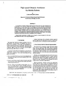
Using this system (shown in Figure I), real-time digital image data was recently obtained successfully f?om flight tests conducted at NASA Langley Research Center. These image sequences are valuable for M e r research on obstacle detection algorithms under different conditions (size, contrast, background etc). By discussing the key issues associated with this system, the time necessary for others to implement similar real-time systems can be reduced. Section 2 gives an overview of the realtime image capturing using a high resolution digital camera. Section 3 explains the real-time image recording using a high speed disk array. Section 4 presents the aircraft maneuvers in the flight test. Section 5 deals with the issues of real-time image processing using multiple pipelined processors. Section 6 summarizes the obstacle detection algorithms for both looming and translating targets. Finally, the performance of the system is described in section 7.
L m l ” convol BOX
Figure 1. The system consists of a Windows NT workstation with two internal Datacube MaxPCl image processing cards, and one New Technology Disk (NTD) Recorder. The sensor consists of a KODAK Megaplus ES1.O digital CCD camera and a PENTEX 1-inch lens with motorized aperture control.
2. IMAGE CAPTURING USING THE REMOTE DIGITAL CCD CAMERA AND MOTORIZED LENS A critical component of the vision system is the imaging sensor. A Kodak Megaplus ES1.O charge coupled device (CCD) digital camera with a Cosmicar/Pentax 1 inch (50 mm) motorized lens was chosen, since digital CCD cameras offer superior performance compared to their analog counterparts. Digital cameras are also highly immune to the spatial and temporal artifacts caused by transmission-line noise. The Kodak ES1.O captures 30 fiames per second with a 1K x 1K resolution in a 8 bit format (256 gray levels). It was mounted in the cockpit of a modified Convair C- 131 aircraft, called the Total In-Flight Simulator (TIFS). Because the recording system was located in the aft portion of the aircraft, a 100 foot digital data cable transferred the image data signals to the recording system. The synchronized clock signals generated by the camera were also transferred through the data cable. A good quality cable with low capacitance prevents asynchronism and noise that can occur with lengthy cables. The dynamic range of the captured images was very large due to the variations in factors such as the sun orientation, cloud conditions, and aircraft altitude. To prevent saturation or very low gray levels in the captured images, a motorized aperture lens was installed on the camera and a remote
aperture control box next to the recording system (100 feet fiom the camera). With this motorized aperture, the operator manually adjusted the aperture during the flight. The camera exposure control software provided by Kodak was not used because that could inadvertently produce blurred images (caused by extended exposures) or unacceptable noise levels (caused by brief exposures). Furthermore, it was easier for the operator of these experiments to use a manual knob to change the lens aperture rather than use the software to change the exposure time of the camera. 3. IMAGE RECORDING WITH THE NEW TECHNOLOGY DISK (NTD) A typical flight sequence with a target aircraft in the field-of-view can last several minutes and produce thousands of 1K x 1K images. One means of reducing the massive amount of disk storage space to hold these images is to use compressive algorithms. However, because it was desireable to analyze the raw characteristics of the camera, uncompressed images were stored. For this task, a system recording data at a rate of 30 MBIsecond (or 1.8 GB/minute) was required. To satisfL these large bandwidth and storage requirements, a Pentium 233 workstation (running Windows NT) with two internal MaxPCI cards fiom Datacube, Inc., and an external disk array, called the New Technology Disk (NTD), were used (shown in Figure 2). The MaxPCI is a real-time image processing card with pipelined image processors. It represents a cost-effective way to meet highthroughput, low-latency demands. The data cable was connected fiom the digital camera to one of the MaxPCI cards. The camera sends images through two channels, with odd lines in one channel and even lines in the other channel. The MaxPCI card receives the images through these two channels, with a throughput of 15 MEVsec from each channel. The MaxPCI card was configured so that the two channels are merged to form complete images in the MaxPCI’s memory. Then the images are sent via the MaxVGA bus to the MaxVGA card for display, and via the PCI bus to the Adaptec AIC- 1160 disk controller card for storing. Transfer to the disk controller card was accomplished using High Speed Image Access (HSIA), a technique that moves data directly back and forth between the disk controller card and the MaxPCI’s memory, without being copied in an intermediate memory buffer. This
596
to their needs. The NtdIfLib is integrated with
I L I
1
MaxVGA 1 video card
1 bus
MnxPCl #I with Storage 96& General Purpose PSMOD
Maxbus
Figure 2. The system with two Datacube MaxPCls and a NTD. It is a Pentium PC workstation, consisting of two Datacube MaxPCls and one New Technology Disk (NTD) Recorder. eliminates the copying of data to host memory as it would be required by other disk storage products. Finally, the images are transferred through a Fibre Channel (FC) cable to the NTD, where the images are stored. The Fibre Channel is a technology for transmitting data between computer devices at a data rate of up to 1 GB/sec. Since it is three times faster than the Small System Computer Interface (SCSI), Fibre Channel is expected to replace SCSI as the transmission interhce between .servers and storage devices. The NTD is a Redundant Array of Independent Disks (RAID) sub-system that enables high-speed lossless digital image recording and playback. The NTD used was a four disk array, with 16 GB per disk. With the FC option, it is possible to achieve NTD transports in excess of 32 MB/sec. To achieve the highest access speed, there is no formatting of data storage on the NTD. All images are recorded as plain raw data to the consecutive physical sectors of the NTD. The NTD can record and playback images at a real-time came rate up to 40MB/sec. Datacube offers a helphl graphical user interface (GUI)called MaxLab to control the NTD. The interface of the MaxLab is like a VCR panel. MaxLab was used in the first flight test for image data recording. However, MaxLab is a commercial package usehl only for NTD control, so no additional image processing tasks can be performed simultaneously while recording. Another Callable library, NtdIfLib, is also available for programmers to create their own NTD access programs according
597
ImageFlow, a C-callable library that configures and manages data transfers on the MaxPCI to perform real-time image processing. With the power of the NtdIfLib and ImageFlow programming, the system can not only record the digital images in real-time, it can also be extended to perform several image processing algorithms concurrently. It should be noted that it's not a simple job to develop a parallel program on the MaxPCI since the programmer must know a good deal about the underlying hardware. Moreover, since there is no useful debug tool for Imageflow at this time, the programming task using Imageflow is time-consuming. However, a very satisfactory system can be developed with appropriateeffort.
4. AIRCRAFT MANEUVERS IN THE FLIGHT TEST Two aircraft were involved in this flight test, which was based at NASA Langley Research Center. The TIFS was the host aircraft, and it carried the Kodak camera and Datacube computer. A Beechcraft King Air B-200 was the target aircraft. The purpose of the flight tests was to obtain images containing different maneuvers conducted by the target aircraft. For all maneuvers, the host aircraft had an altitude of 3500 feet and a speed of 159 knots. Two classes of maneuvers were flown.
In the translating maneuver (shown in Figure 3(a)), the target aircraft translated (moved) in the image sequence. It was performed with the target aircraft crossing perpendicular to the direction of motion of the host aircraft. The speed of the target aircraft was 159 knots. This maneuver was performed for different vertical and horizontal separations. Images were recorded with the target aircraft 500 feet below and 500 feet above the host aircraft at distances of about 1, 2,3,4 and 5 nautical miles. Recording ended when the target aircraft left the field of view of the camera. In the contraction maneuver (shown in Figure 3(b)), the target aircraft maintained a fixed position in the image surface as it flew away from the host aircraft. The target aircraft speed was 209 knots. Images were recorded with the target aircraft ascending at 500 feet per minute, descending at 500 feet per minute, or maintaining a fixed altitude. Recording ended when the target aircraft was about 5 miles fiom the host aircraft. The images from this
+
target
(a) (b) Figure 3. Two kinds of flight maneuvers. (a) Translating maneuver: the target aircraft crossed in front of the host aircraft with a vertical separation of 500 ft. (b) Looming maneuver: the target aircraft maintained a fixed position in the image window by flying directly away from the host aircraft. The target aircraft maintained the same altitude as the host aircraft. (Not drawn to scale.) sequence can be played backwards to simulate the target aircraft motion that occurs with a collision. Two flight tests were conducted over a several day period in January and September, 1999. The first flight test focused on image capturing and recording, while the second flight test performed image capturing, recording, and processing concurrently. By recording images over a multiple day period in each flight test, a range of contrast In addition, the conditions was obtained. background of the target varied depending on its altitude. This approach provided a comprehensive set of images for testing the image processing algorithms under different conditions.
5. IMAGE PROCESSING WITH THE MAXPCI CARDS The MaxPCI is a real-time image processing card with pipelined processors. It uses a Windows NT workstation as a host machine and supports multiple simultaneous pipelines that can be switched by software at read-time fkame rates. Each MaxPCI card consists of five modular hardware devices and a set of memories connected by a large programmable switch as shown in Figure 4. The first device is the MaxAcq acquisition unit that receives either a digital or an analog signal fkom the camera. The second device is the MaxVGA display unit that outputs the video signal to the MaxVGA video card. The third device is the Arithmetic Unit (AU) which performs arithmetic and logical operations. The fourth device
1
Host machine: P e p c
1
Figure 4. Each MaxPCl is composed of a MaxAcq acquisition unit, a MaxVGA display unit, five Advanced Memorys (AM), two Arithmetic Units (AU), two Look-Up Tables (LUT) and two PSMOD add-on modules. is the Look-Up Table (LUT) that performs pixel value transformations. The fifth device is the Advanced Memories (AM) component which can receive an image fkom the cross-point switch and transmit another image to the cross-point switch at the same time. The AM also allows the host computer to read or mite pixels via the PCI bus. Moreover, each MaxPCI may be extended by the selection of two add-on processing and storage modules (PSMOD). The variety of the PSMODs enables users to balance their needs of processing, memory and resources. The first MaxPCI in the test flight system was equipped with a Storage96 (ST) and a General Purpose (GP) PSMOD, while the second MaxPCI was equipped with a GP and a Convolver200 PSMOD. It should be noted that the ST is the same as an AM while the GP is similar to an AU. All of these devices operate on pixel arrays at 40 MHz. Table 1 lists the main resources in each MaxPCI card. The MaxPCIs communicate with each other through two buses called Maxbuses. Each Maxbus has a bandwidth of 160 MEVsec. The MaxVGA is a separate display card, which inputs images !?om the MaxPCI through a private MaxVGA bus. Hence, the display can be accelerated without interfering with the PCI bus traffic. ImageFlow programming allows the programmer to specifl connections between the processing elements inside hardware devices, as well as between ports on the cross-point switch. It also provides access to attributes associated with each processing element.
598
Table 1. The number of main resources in each MaxPCI card. IResource
(MaxPCIWIMaxPCI#ll
lkithmetic Unit Arithmetic Memory
1
2 5
1
2
y1i1
Look-Up Table
2
2
Convolver200 PSMOD
0
1
rl'urposePSMOD1 Storage96 PSMOD
1
5
Analog Acquisition Digital Acquisition
6. OBSTACLE DETECTION ALGORITHMS Obstacle detection using image processing requires robust, reliable and fast techniques. These techniques should provide a high probability of detection while maintaining a low probability of hlse alarm in noisy, cluttered images of possible targets, exhibiting a wide range of complexities. The size of the image target can be quite small, fiom sub-pixel to a few pixels in size. Furthermore, the detection algorithm must report such targets in a timely fishion, imposing severe constraints on their execution time. Finally, the system must not only work well under the controlled conditions found in a laboratory and with data closely matching the hypothesis used in the design process, but it must be insensitive-i.e., must be robust -- to data uncertainty due to various sources, including sensor noise, weather conditions, and cluttered backgrounds. Over the past year, several algorithms were combined to form a composite system for detection of looming targets [5]. The steps that form this composite system are: (1) Temporal Averaging: For objects in a uniform background, having a very small image motion, such as those on a collision or nearcollision course. When the target motion is small, temporal averaging improves the SNR and reduces the processing rate required for subsequent steps. (2) Pyramid construction with low-stop or morphological filtering: This is a pre-processing step in which a pyamid is constructed to accommodate different sizes and velocities of objects. Low-stop filtering [6] is performed at each pyramid level to
599
Figure 5. Tracking algorithm applied on an image sequence with the target aircraft translating from the right to the left side of the image at a distance of three nautical miles. The target aircraft is located at the end of the track in this image. remove background intensity. There is an option to perform morphological filtering [2] in place of lowstop filtering at every pyramid level. This can be done when the background contains clutter due to clouds andor ground to improve perfonnance. (3) Dynamic Programming: A dynamic programming algorithm [3] is performed on preprocessed fiames to integrate the signal over a number of fiames by taking the target motion into consideration. It should be noted that one or more of these steps can be bypassed so that any of the basic algorithms described above can be tested individually using the same system. The above target detection algorithms were implemented on the Datacube MaxPCI system. In addition to detection of objects on a collision course, it is useh1 to monitor the objects that are crossing in fiont of the aircraft. For this purpose, a system was designed to specifically detect objects which have a translating motion in the image. To distinguish translating objects fiom ground or cloud clutter, the following criteria was used: (1) The object should have sufficient signal strength. (2) The object should have an image velocity greater than a threshold. (3) The object should have a consistent motion, i.e., its velocity. The algorithm to detect translating objects has also been implemented on the Datacube MaxPCI system to obtain real time performance. The system
was mounted on the host flight aircraft and performed well in detecting and tracking objects. The algorithm is divided into two concurrent parts. These parts are: (1) Image processing steps which remove most of the clutter, and isolate potential features which could be translating objects. This steps consist of temporal differencing, low-stop filtering, non-maximum suppressing (NMS) and feature extraction. These image operations are suitable for a pipelined architecture, and can be done in integer format. Hence, these steps are implemented on the Datacube MaxPCI machine. The output of this part is a list of image points which are likely to contain the target objects, along with their signal strengths. (2) Tracking these features using a Kalman filter to distinguish genuine translating objects from background clutter which was not separated by the simple image processing steps of the first part. Since the first part has reduced the volume of data to be operated on, more complicated target tracking algorithms can be implemented even on the host PC associated with Datacube. The threshold used in the first part is adjusted dynamically to give a nearly constant number of features for the second part so that they can be processed in real time using the slower host. This is known as the rate constraint [4]. Figure 5 shows a trace of the tracking algorithm applied on an image sequence with the target aircraft translating fiom the right to the left side of the image. A detection is shown by drawing a small black square around the detected position. The distance between the host and target aircraft is 3 nautical miles in this scenario. Table 2 summarizes the performance of the translating target tracking algorithm for a number of distances between host and target aircraft. The false alarm (FA) rate is the ratio of the total number of false alarms throughout the sequence to the number of image frames in the sequence. The miss detection (MD) rate is the ratio of the number of frames in which the target was missed to the total number of frames. The false alarm rate depends on the amount of clutter in the images, whereas the miss detection rate depends on the target size and contrast, and therefore increases with the target distance in most cases. Since false alarms can be very annoying to pilots, a low false alarm rate was more desirable than a low miss detection rate. Hence, the parameters of the tracking algorithm were selected deliberately to reduce the Blse alarm rate. The tracking parameters are the same for all scenarios. It is possible to get better performance by adjusting parameters
Table 2. The performance of the translating target tracking algorithm for a number of target distances in nautical miles (nmi). The algorithm was executed at 15 FPS on the Datacube MaxPCl system. Target Distance MD Rate FA Rate 1.2
0.159
0.063
0.061
0.000
0.113
0.000
2.0
0.394
0.000
2.4
0.059
0.000
3.0
0.053
0.000
4.7
I
~
0.335
I
0.183
5.0
0.192
0.038
5.4
0.643
0.000
I
individually according to the characteristics (such as the clutter level) of each scenario. 7. CONCLUSION
The feasibility of the real-time image capturing, recording and processing system was demonstrated by two flight tests conducted by NASA this year. During the first flight test in January 1999, image sequences were captured and recorded successfblly at a rate of 30 frameshecond. Ten real-time image sequences with translating targets, and six image sequences with looming targets were obtained, containing 86 GB (87819 frames) data total. The tracking algorithms were designed and fine-tuned using these image sequences. During the second flight test in September 1999, not only the real-time image capturing and recording was performed but also the translating target tracking algorithm was executed concurrently at a rate of 15 frameshecond. Output of the algorithm was displayed on an X V S display screen in the cockpit. Nine real-time image sequences with translating targets were obtained, containing 23 GB (23254 frames) data. It was observed that the system successfblly detected and tracked translating objects during the flight test. 8. APPENDIX
600
[I] D. Wood, “Jane’s World Aircraji Recognition Handbook”, Jane’s ‘Information Group Ltd.,
[2]
[3]
[4]
[SI
Coulsdon, UK, 1992. D. Casasent and A. Ye, “Detection Filters and Algorithm Fusion for ATR”, IEEE Trans. on Image Processing, 6(1), 114-125, January 1997. J. Arnold, S . Shaw and H. Pastemack, “Efficient Target Tracking using Dynamic Programming”, lEEE Trans. on Aerospace and Electronic Systems, 29( I), 44-56, January 1993. J. Bird and M. Goulding, “Rate-constrained target detection.”, IEEE Trans. On Aerospace and Electronic System, 28(2):491-503,April 1992. R. Kasturi, 0. Camps, L. Coraor, K. Hartman, T. Gandhi, and M. Yang, “PeTformance characterization of target detection algorithms for aircraji navigation.”, Technical report, Dept. of Computer Science and Engineering, The Pennsylvania State University, 1998.
[6] P. Burt. “Fast filter transfrom for image processing.”, Computer Vision, Graphics and Image Processing, 16:20-51, 1981. 9. AUTHOR BIOGRAPHIES MAU-TSUEN YANG received his B.S degree in applied mathematics from the National Tsing-Hua University, Taiwan. He works currently as a Ph.D. student in the Computer Vision Lab. in the Department of Computer Science & Engineering of The Pennsylvania State University. His research interests include real-time applications, parallel processing, parallel scheduling, image processing, and computer vision.
TARAK GANDHI received his Bachelor of Technology degree in Computer Science and Engineering at the Indian Institute of Technology, Bombay, India in 1991. He received M.S. degree in 1994 and Ph.D. degree in 2000 in the Department of Computer Science & Engineering of The Pennsylvania State University. His research interests include image processing, computer vision, motion analysis, target detection, and pattern recognition. He works currently as a vision software engineer in ADEPT Technology, Inc. RANGACHAR KASTURI is a professor in the Department of Computer Science and Engineering of The Pennsylvania State University. He joined Penn State in 1982 after completing his graduate studies at Texas Tech University (Ph.D., 1982; M.S.E.E., 1980). He was the Editor-in-Chief of the IEEE Transactions on Pattern Analysis and Machine Intelligence during 1995-98; he was an associate editor during 1991-94. He was the Editor-in-Chief of
601
the Machine Vision and Applications journal during 1993-94. He is a coauthor of the text book Machine Vision. His primary research focus has been in the area of intelligent interpretation of document images and video sequences.
LEE CORAOR received the Ph.D. in Electrical Engineering from the University of Iowa, July 1978. He was a member of the faculty at The Southern Illinois University-Carbondale fiom August 1978 to August 198Q; and then joined the Penn State electrical engineering faculty. He is currently an Associate Professor in the Department of Computer Science and Engineering. His current research interests include reconfigurable computing applications, intelligent memory designs, computer architecture and digital systems. Recent projects have included: the use of reconfigurable FPGA’s for implementing event-driven simulation, and the design and implementation of a dual computer control system for a micro-gravity continuous flow electrophoresis system.
OCTAVIA CAMPS received her M.S. and Ph.D. degrees in electrical engineering fiom the University of Washington in 1987 and 1992, respectively. Dr. Camps then joined the Penn State faculty as an assistant professor in the electrical engineering department. Dr. Camps has served as a reviewer for multiple journals, and as session chair for several conferences in her field. She is the Object Recognition Area Chair on the program committee for the 1999, IEEE Computer Vision and Pattern Recognition Conference. Her main areas of research are in computer vision, image processing and pattern recognition. She is currently conducting research on robust 3D object recognition in the presence of clutter and image data uncertainty, vision-based aircraft navigation, target tracking using robust dynamic vision and control, and 3D model reconstruction from sensed data using purposive vision.
JEFFREY MCCANDLESS is a Senior Research Associate at NASA Ames Research Center. He obtained his W.D. in Vision Science in 1996 fiom U.C. Berkeley, where he developed neural network models of brainstem activity controlling eye movements. After completing his Ph.D., he began working at NASA to develop image processing software to detect aircraft in video images. Currently he is helping develop new cockpit displays for the Space Shuttle. For- this project, he is collaborating with astronauts, mission controllers, and programmers at Johnson Space Center.