Sep 29, 2009 ... Enclosed by such an illusion device, an arbitrary object ... and permeability, the
illusion device proposed in this letter has positive permittivity ...
arXiv:0909.5255v1 [physics.optics] 29 Sep 2009
Moving Targets Virtually Via Composite Optical Transformation Wei Xiang Jiang and Tie Jun Cui∗ State Key Laboratory of Millimeter Waves and Institute of Target Characteristics and Identification Department of Radio Engineering, Southeast University, Nanjing 210096, P. R. China.
Abstract We propose a composite optical transformation to design an illusion device which can move the image of a target from one place to another place. Enclosed by such an illusion device, an arbitrary object located at one place appears to be at another place virtually. Different from the published shiftedposition cloak which is composed of the left-handed materials with simultaneously negative permittivity and permeability, the illusion device proposed in this letter has positive permittivity and permeability. Hence proposed illusion device could be realized by artificial metamaterials.
PACS numbers. 41.20.Jb, 42.25.Gy, 42.79.-e
∗
[email protected]
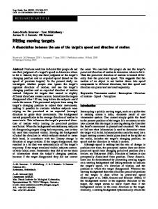
2 In the past few years, great attention has been paid to the transformation optics [1-21]. Among the various optical transformation devices, the most exciting and fascinating one is the invisibility cloak [1-7]. The first free-space cloak with simplified medium parameters was verified experimentally at the microwave frequency [3]. Recently, a carpet cloak has been proposed [4] and confirmed in microwave frequencies [5] and then in optical frequencies [6,7]. Inspired by these pioneering work, other applications such as the rotation of electromagnetic (EM) waves [10,11], and omnidirectional retroreflectors [12,13] have been proposed and investigated. More recently, Lai et al. have proposed an interesting idea of illusion optics, which makes a target with arbitrary shape and material properties look like another object of some other shape and material makeup [19]. Some special illusion devices have been discussed before this, such as the super absorber [13], the superscatterer [16], the shifted-position cloak [18], and the cylindrical superlens [21]. However, all above-mentioned illusion devices are composed of the left-handed materials with simultaneously negative permittivity and permeability. Hence such illusion devices are highly demanding on the material properties, and the applications are possible to be limited to the realm of theory. In this letter, we propose a composite optical transformation to design an illusion device which makes the enclosed actual object located at one place appear to be at another place. Such an illusion device shows unconventional EM properties as verified by accurately numerical simulations. We try to make the illusion device be fairly realizable. Unlike the published illusion devices which are composed of left-handed materials [13, 16-19, 21], all permittivity and permeability components of the proposed illusion device are positive. Hence the presented method makes it possible to realize the illusion device by using the modern metamaterials. A concise schematic to design the proposed illusion device is illustrated in Fig. 1. A car at Position A is enclosed with an illusion device, as shown in Fig. 1(a). Such an illusion device make any detector outside the virtual boundary (surface s) observe the EM fields of a virtual car at Position B (shown in Fig. 1(c)) instead of the actual one. In other words, the illusion device makes the EM-field distributions outside the virtual boundary in both the virtual and physical spaces exactly the same, regardless the direction from which the EM waves are incident. The composite coordinate transformation of the illusion device contains two sub-mappings. First, we map the first virtual space (the free space outside the car in the virtual space in Fig. 1(c)) into a smaller annulus region (the light green region in Fig. 1(b)). Second, we transform the second virtual space (light green region in Fig. 1(b)) into the physical space (dark green region in Fig. 1(a)).
3 The electric permittivity and magnetic permeability tensors of the illusion device are calculated by ε′′ = Λ2 Λ1 εΛ1 T Λ2 T / det(Λ1 Λ2 ),
µ′′ = Λ2 Λ1 µΛ1 T Λ2 T / det(Λ1 Λ2 ),
(1)
in which (ε, µ) and (ε′′ , µ′′ ) are the permittivity and permeability tensors in the first virtual space (illusion space) and the physical space, respectively, and Λ1 and Λ2 are the Jacobian transformation matrices with ′′
′
′
components Λ1ij = ∂xi /∂xj and Λ2ij = ∂xi /∂xj corresponding to the mapping from the first virtual space to the second virtual space, and the mapping from the second virtual space to the physical space, respectively. Similar to other optical transformation devices, the EM fields in the illusion device can be obtained from the transformation optics [1,2] as E′′ = (Λ2 T )−1 (Λ1 T )−1 E and H′′ = (Λ2 T )−1 (Λ1 T )−1 H, where E and H are electric and magnetic fields in the first virtual space, respectively. Because the virtual boundary s is mapped to itself during these two sub-mappings Λ1 and Λ2 , we have E′′ t = E′t = Et and H′′t = H′t = Ht , where the subscript t indicates the transverse components along the surface s. That is to say, the tangential components of the EM fields on the whole virtual boundary (s) are exactly the same in both physical and virtual spaces. Hence the EM fields outside the illusion device are also exactly the same by using the uniqueness theorem. Any observers outside the illusion device will perceive the scattered fields as if they were scattered from a car at Position B. For a specific example, we consider an illusion device which can move the image of a metallic cylinder from one place to another place. To design such an illusion device, we construct a composite transformation which contains two sub-mappings in the Cartesian coordinate system, the first sub-mapping can be expressed as r1′ (x − a1 − a2 ) + a1 + a2 , r ′ r y y′ = 1 , r
x′ =
z ′ = z,
(2) (3) (4)
where (a1 + a2 , 0), (0, 0) and (a1 , 0) are the centers of virtual and actual metallic cylinders and circular virtual region, respectively, r1′ = (R12 − R11 )(r − r0 )/(R12 − r0 ) + R11 , R1i = −(x − a1 − a2 )(a1 + a2 )/r + p p b2i − (a1 + a2 )2 y 2 /r2 , (i = 1, 2), and r = (x − a1 − a2 )2 + y 2 . Such a sub-mapping describes a similar transformation that maps the blank region in the virtual space in Fig. 1(c) into the light green region in
4 Fig. 1(b). The second sub-mapping can be expressed as r′′ x′ , r2′ r′′ y ′ y ′′ = ′ , r2
x′′ =
z ′′ = z ′ ,
(5) (6) (7)
p where r′′ = (R22 − r1 )(r′ − R21 )/(R22 − R21 ) + r1 , R2i = −(x′ − a1 )a1 /r′ + b2i − a21 y ′2 /r′2 , (i = 1, 2), and p r2′ = x′2 + y ′2 . This sub-mapping describes a similar transformation that maps the light green region in Fig. 1(b) into the dark green region in Fig. 1(a). The converse transformation of the virtual variables and the physical variables can be constructed by Eqs. (2)-(7). Then the constitutive parameters of the illusion device can be calculated by formulae (1). We remark that the EM parameters of the illusion device can also be obtained by another process for such a composite transformation. A function relationship between (x′′ , y ′′ , z ′′ ) and (x, y, z) can be found from Eqs. (2)-(7) as follows, x′′ = f (x, y),
(8)
y ′′ = g(x, y),
(9)
z ′′ = z.
(10)
Based on the above composite transformation, the permittivity and permeability of the illusion device are expressed as ε′′xx = µ′′xx = (fx2 + fy2 )/(fx gy − fy gx ),
(11)
ε′′yy = µ′′yy = (gx2 + gy2 )/(fx gy − fy gx ),
(12)
ε′′xy = (fx gx + fy gy )/(fx gy − fy gx ) = ε′yx ,
(13)
ε′′zz = µ′′zz = 1/(fx gy − fy gx ),
(14)
ε′′xz = ε′′yz = µ′′zx = µ′′zy = 0,
(15)
µ′′xy = µ′′yx = ε′′xy ,
(16)
where we denote the partial derivative of the function f (x, y) to x as fx . We have assumed that the background profile be free space, i.e., ε = ε0 I and µ = µ0 I. Obviously, these two sub-mappings are not conformal transformations, hence some non-diagonal components of the permittivity and permeability tensors are non-zero. But in the real fabrications, it is necessary
5 that the material parameters ε′′ and µ′′ are denoted in diagonal tensors. The symmetry of the real tensors ε′′ and µ′′ ensure that a rotation transformation which maps a symmetric tensor into a diagonal one always exists. When a transverse-electric (TE) polarized plane wave is incident upon an enclosed metallic cylinder with infinite length, there exists only z component of electric field, hence only µ′′xx , µ′′xy , µ′′yy and ε′′zz are of interest and must satisfy the request of Eqs. (11)-(16). Therefore, the EM parameters in the eigen-basis can be expressed as ′′
µ1 = µ2 =
′′
µxx + µyy −
q µ′′xx2 − 2µ′′xx µ′′yy + µ′′yy2 + 4µ′′xy
2 q ′′ ′′ ′′ 2 µxx + µyy + µxx − 2µ′′xx µ′′yy + µ′′yy2 + 4µ′′xy 2
,
(17)
,
(18)
′′
εz = εzz ,
(19)
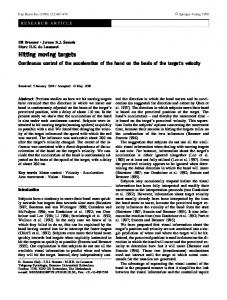
and all the off-diagonal components equal zero. In such a case, all components µ1 , µ2 , and εz are finite and positive. Also, µ2 is always greater than µ1 . Unlike the earlier-proposed shifted-position cloak which consists of left-handed materials with double negative constitutive parameters [18], the illusion device here is only composed of one layer of inhomogeneous and anisotropic medium. In order to verify the design of the illusion device, we make accurately numerical simulations using the software package, COMSOL Multiphysics, which is based on the finite-element method. We consider an illusion device which moves a metallic cylinder from one place virtually to another place. In this example, we choose a1 = 0.1 m, a2 = 0.05 m, r0 = r1 = 0.03 m, b1 =0.13 m, and b2 = 0.15 m. Under the illumination of TE-polarized waves, only µ1 , µ2 and εz are of interest. The distributions of principle components µ1 , µ2 and εz are illustrated in Figure 2, from which we clearly observe that all values are finite and positive. It is worth to note that these two sub-mappings in this illusion device are compressing and extending mappings, respectively, instead of the folding of geometry [17-21]. Hence any material parameters of the illusion device are not negative. Similar metamaterial structures have been extensively investigated and fabricated in the experiment of free-space cloaks and other devices at microwave frequencies [3,11]. Figure 3 illustrates the numerical results of total electric fields for the above illusion device. The plane waves are incident vertically from the bottom to the top at 6 GHz. Figures 3(a) and 3(c) show the total-field distributions of the metallic cylinder located at different places. When the metallic cylinder enclosed by the shifted-position illusion device, the scattered pattern from the metallic cylinder will be changed as if the metallic cylinder was at another place. This can be clearly observed by comparing the scattered patterns of the metallic cylinder coated by the illusion device shown in Fig. 3(b) and the metallic cylinder shown in Fig.
6 3(c). Inside the virtual boundary, the EM-field distributions in Figs. 3(b) and 3(c) are very different. But the total-field distributions are exactly the same outside the virtual boundary. A position-moving illusion has been generated. In summary, we have presented a composite optical transformation to design a kind of illusion device, which can move the target from one place to another place virtually by using metamaterials. In such an illusion device, all diagonal components of constitutive tensors are positive and all off-diagonal ones are zero, hence the illusion device could be realized using artificial metamaterial structures. This work was supported in part by the National Science Foundation of China under Grant Nos. 60990320, 60990324, 60671015, 60871016, and 60901011, in part by the Natural Science Foundation of Jiangsu Province under Grant No. BK2008031, and in part by the 111 Project under Grant No. 111-205. WXJ acknowledges the support from the Graduate Innovation Program of Jiangsu Province under No. CX08B 074Z.
7
References [1] J. B. Pendry, D. Schurig, and D. R. Smith, Science 312, 1780 (2006). [2] U. Leonhardt, Science 312, 1777 (2006). [3] D. Schurig, J. J. Mock, B. J. Justice, S. A. Cummer, J. B. Pendry, A. F. Starr, and D. R. Smith, Science 314, 977 (2006). [4] J. Li and J. B. Pendry, Phys. Rev. Lett. 101, 203901 (2008). [5] R. Liu, C. Ji, J. J. Mock, J. Y. Chin, T. J. Cui, D. R. Smith, Science 323, 366 (2009). [6] L. H. Gabrielli, J. Cardenas, C. B. Poitras and M. Lipson, Nat. Photon. 3, 461 (2009). [7] J. Valentine, J. Li, T. Zentgraf, G. Bartal, and X. Zhang, Nat. Mater. 8, 568 (2009). [8] H. Chen and C. T. Chan, Appl. Phys. Lett. 90, 241105 (2007). [9] H. Chen, B. Hou, S. Chen, X. Ao, W. Wen, and C. T. Chan, Phys. Rev. Lett. 102, 183903 (2009). [10] T. Tyc and U. Leonhardt, New J. Phys. 10, 115038 (2008). [11] Y. G. Ma, C. K. Ong, T. Tyc, and U. Leonhardt, Nat. Mater. 8, 639 (2009). [12] W. X. Jiang, T. J. Cui, H. F. Ma, X. M. Yang, and Q. Cheng, Appl. Phys. Lett. 93, 221906 (2008). [13] J. Ng, H.Y. Chen, and C. T. Chan, Opt. Lett. 34, 644 (2009). [14] W. X. Jiang, T. J. Cui, X. Y. Zhou, X. M. Yang, and Q. Cheng, Phys. Rev. E 78, 066607 (2008). [15] M. Rahm, S. A. Cummer, D. Schurig, J. B. Pendry, and D. R. Smith, Phys. Rev. Lett. 100, 063903 (2008). [16] T. Yang, H.Y. Chen, X. D. Luo, and H. R. Ma, Opt. Express 16, 18545 (2008). [17] Y. Lai, H. Chen, Z. Q. Zhang, and C. T. Chan. Phys. Rev. Lett. 102, 093901 (2009). [18] Y. Luo, J. J. Zhang, H. Chen, B.-I. Wu, and J. A. Kong, arXiv: 0904.1463. [19] Y. Lai, J. Ng, H. Y. Chen, D. Z. Han, J. J. Xiao, Z. Q. Zhang, and C. T. Chan, Phys. Rev. Lett. 102, 253902 (2009). [20] U. Leonhardt and T. G. Philbin, arXiv: 0805.4778. [21] M. Yan, W. Yan, and M. Qiu, Phys. Rev. B 78, 125113 (2008).
8
List of Figure Captions Fig. 1: (color online) A concise scheme of an illusion device that moves the image of a car from one position to another one. (a) A car at Position A enclosed with the illusion device (dark green region). (b) A bigger illusion car in the second virtual space. (c) The illusion car at Position B in first virtual space.
Fig. 2: (color online) The parameter distributions of the illusion device, (a) εz , (b) µ1 , and (c) µ2 .
Fig. 3: (color online) The total electric-field distributions in the computational domain for (a) a metallic cylinder without the illusion device; (b) the actual metallic cylinder with the illusion device (dashed circle means a virtual metallic cylinder); and (c) the metallic cylinder at another place when the plane waves are incident vertically from the bottom to the top.