Multi- Agent ased Control erne1 for Flexible Automated ... named TOFAK( Task Oriented Flexible Automation .... by most of vendors throughout the world.
Proc&ings 0: :ne iQSb 161 : International ConferenLe on Robotics & Autoination 1euven, Belgium May 1998
Multi- Agent
ased Control erne1 for Flexible Automated Production System
Sung-Hahn Liu and Li-Chen Fu Dept. of Computer Science and Information Engineering National Taiwan University,Taipei,Taiwan,R.O.C Jung-Hua Yang Dept. of Electrical Engineering Yung Ta Junior College of Technology & Commerce February 26, 1998
Abstract An Intelligent Automated Robotic Assembly System consists of several subsystems capable of providing dynamic interactions with the environment in order to accomplish a task properly. These subsystems perform various functions like data gathering, decision making, and task execution. Although a great deal of work has been done on individual subsystems, more attention must be given to the way how these subsystems are integrated so as to achieve the high efficiency of automated production. In this paper, we propose a cooperative multi-agent model of a shop floor control system architecture of robotic assembly atuomation and extend this model to all automated production system. Based on this model, we develop a control kernel named TOFAK( Task Oriented Flexible Automation Kernel ) to support users to easily implement any shop floor control system. The by-product is to allow system designers to easily expand an existing system or to integrate several automation systems which are all controlled by TOFAK.
1
Introduction
Due to the rapid change in consumers world requirements, market flexibility has become one of the most important factors in manufacturing environment within the recent years. Large industial companies have realized that flexible production systems are capable of rapid adaptation to varying number and various kinds of products. In general, flexibility of a control system in automated systems is greatly emphasized nowadays because it can make the system more adaptable to various situations. One kind of flexibility is the capacity of on-line reconfiguration. In [lo], a general control architecture for multiple vehicles is proposed and dynamic reconfiguration is allowed. Moreover, in [3] and [6], flexible control systems are imdemented for flexible automated Droduction systems. Recently, formal languages [7]are also adopted in the field of system control [ 5 ] . Hierarchical control methods [a, 3 , 4 , 5, 101 and objected-orient approaches [l,6, 91 both contribute to this subject because they
0-7803-4300-~-5/98 $10.000 1998 IEEE
provide systematic ways to analyze and t o build a control system, and then increase the reusablilty of the components in the programs. In [8],a multi-agent control system were introduced. A new distributed object model has been discussed recently, namely CORBA [ll].The new features of CORBA will be very helpful in integrating diverse production systems. For the goal of integrating scheduling systems and operatioing systems on the shop floor, we here devise a flexible model of manufacturing system and a flexible control kernel for that model to solve those problems in the domain of shop floor control. The model is called Cooperative Multi-Agent Architecture (CMA) and the control kernel is called the Task Oriented Flexible Automation Kernel (TOFAK) .
CMA: Cooperative Multi-Agent Architecture
2
2.1
Agent Definition
In this model, the basic element is an agent, which is viewed as anything that can perceive its environment through sensors and can act on the environment through effectors. In automated production systems, an agent can be regarded as a combination of software agent and robotic agent. That is, an agent is a program that has the ability of communicating with its environment and can also control real equipment to produce parts through physical link. In CMA, we define two kinds of agent : tack agent and communication agent. These two kinds of agent are described below.
2134
0
Task Agent: has both the ability t o perform some tasks and the ability to communicate with domain server via TCP/IP.
0
Communication Agent: links application software with different communication protocol (other than TCP/IP) to domain kernel.
Agent A requests the task on agent B
TASK
t
Process with different protocol
(DDE,OLE,..,
TASK
etc.) Co"""lcati""
Task Agent
AZepnt
TOFAK
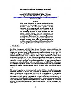
Figure 1: CMA Model Figure 2: Iksk Execution Process
2.2
CMA Model 2.3
The main goal of this model is to provide a flexible manufacturing system. It is agreed that a successful automated production system should always try to allow use of different operating system (OS). For this reason, our model will allow applications running, on different platforms. For example, application under DOS and application under UNIX can work ttogether without any incompatibility. The whole architecture model is shown in Figure.1, which has two basic entities shown as follows: 0
TOFAK (Task Oriented Flexible Autornation Kernel): the task control kernel in the
Useful Properties
In the definition of the CMA model, it can be found easy to integrate legacy systems into a new one, which complies with the CMA model. The legacy automation system can be ab system without communication ability or a system with different communication protocol (COM,OLE,or RPC). Besides, since TOFAK has communication ability, itself is also an agent. 13ecanse TOFAK can be treated like an agent, it can be connected to an upper level TOFAK, and hence can provide a hierarchical model of CMA, as shown in Figure.3.
CMA model. 0
Agent: a program which is able to perform some tasks and t o connect the TOFAK.
By Figure.1, there are many agents working together, each agent has its own job function. AIDagent may need t o handle the activity of physical robtot arm, managing a vision system, or just a scheduler program. Thus, every agent performs some specific task and changes message with one another, of which all these efforts are to achieve the goal of a productmion system. As a result, communication network becomes indispensible due t o the need. In this research work, the network protocol we choose is the TCP/IP, which is the most popular network protocol and is supported by most of vendors throughout the world. Because of the above features of the CMA, we can easily integrate many small systems into a new one. In CMA, we can see that all agents are connected to the TOFAK and change messages transparently. The TOFAK is a broker based control kernel, which plays the most important part in this model. All tasks are sent to TOFAK first, and then TOFAK will decide how these tasks should be executed. Despite that, any agent does not need to know the addresses of other agents. Once an agent wants to communicate with another agent, it simply gives TOFAK the name of the target agent and all necessary parameters (Figure.2).
AGENT
AGENT
AGENT
Figure 3: Hierarchical Model of CMA As we have defined before, each agent should be associated with some kind of task. Therefore, TOFAK also has some task defined on it. An example of the task on TOFAK maybe is to report to the upper level system or to execute ,someorders from the upper level system.
3
TOFAK: Task Oriented Flexible Automation Kernel
Since the role of TOFAK in CMA model has been introduced in the previous section, a complete description of the architecture of TOFAK will be provided here. The basic architecture of TOFAK is illustrated in Figure 4.
21 35
Statusxepost Section The cell designel caii c a k e a list of agent names on this section. Then, :he system will automatically send agent status to every agent that is specified in this section whenever there is a status change in any of the agents.
3.2
I
‘
Figure 4: TOFAK Architecture
3.1
CMA Specification
The CMA specification contains all necessary data that TOFAK needs when building a brand new manufacturing environment. It is nothing but a text file such that anybody can tailor it for his own manufacturing cell. There are four sections in a CMA specification : Communication, Agent, Group and System-Task, which are respectively explained below.
Communication Section Because TOFAK is built on TCP/IP, there are certainly some information about the communication part that must be filled in inside the control kernel. For example, the socket port number and the name of this TOFAK.
Agent Section This section is focused on the issues like which agents will join the cell and what tasks can be provided by these agents. An agent which wants t o enter this TOFAK will not be accepted if the name of this agent does not appear in this section. The task requested by some agent will be refused if the cell designer does not specify that task in the agent section. Therefore, this section allows one to layout his working environment flexibly in a transparent manner.
Network Service Center
The Network Service Center (NSC) is the communication part in TOFAK. It takes responsibility of building connection among other components in a CMA environment. That is, it builds connections between agents and TOFAK and between the upper level TOFAK and the TOFAK itself. TOFAK sends and receives requests via NSC. There are two kinds of connections that need to be established. One is the registration request from an agent to TOFAK. When the agent undergoes the registration procedure, NSC will make a logical connection between the agent and TOFAK so that messages can be exchanged.
3.3
Internal Task Interpreter
There are two kinds of task in CMA environment. One is the agent task and the other is the internal task provided by kernel itself. When NSC receives a task request from the agent, it will be processed in two ways. If it is an internal task, then the NSC will send it into Internal Task Interpreter immediately. Otherwise, it will be sent into Task Manager instead.
3.4
Database Manager
Within our system, there are a large amount of data that need to be stored and retrieved such as task information, agent status, product working progress and error message. Since the data set will be very complex, huge and hard to handle, we prefer to design a special element for handling every data set we need in our system. This is what Database Manager needs to serve in TOFAK.
3.5
Task Manager
Group Section In TOFAK, the system designer can integrate several agents into one group and then can send message to these agents by sending mes-
^L_
sage t o this group. Agents in this TOFAK can send information to each group by using the interne1 task : SENDGROUP.
I “
System-Task Section As has been pointed out earlier, a TOFAK can be an agent itself, and hence some task may be provided by it. This section will be used to implement those tasks if that will be the case. One can combine several internal tasks into a system task. To do so, one must first declare a unique task name and associate it with a list of internal tasks. 21 36
.
0 0
.
Figure 5: Task Manager
The major task of this component is that collecting all task request in this system and then check iris vitlidness and correctness, i.e., whether the task is clearly defined in CMA specification and whether the .;ask carries the right parameters with it. If a task belongs to agent task type, the Task Manager will ask the Database Manager to add this task into the task table. All tasks in task table is indexed by its priority and would be retrived by Task Dispatcher one by one from top to end. The concept of Task Manager is shown in Figure.5.
3.6
Task Executor
When there is an executable task coming, the Task Executor will find an agent which can perform t,his task and then invoke this task on remote agent. When the agent is executing this task, the Task Executor simply puts the task into running state and continues the next task invoking. Note that, because all the internal task is sent to the Internal Task Interpreter, the Task Executor only invokes the remote tasks. After an agent finished a task, it would send message to TOITAH: to notify the Task Executor. It will move this task into finishing state and drop this task from the task table. The reply message will be sent to the request agent also.
3.8
task
Task Dispatcher
The Task Dispatcher takes a task from the task table maintained by the Database Manager if the task matchs these two condition: has the highest priority and the invoked agent is ready for serving this task. If the agent that provides this task is ready for accepting work, then it puts the task to the Task Executor for execution.
3.7
delete
Figure 6: Error Manager Concept
3.10
We provide a windows based interface in order t o present how system w'orks, how message is being exchanged, and what kind of problem exists. By this, we can communicate with the operator and get his feedback. The supervisory control with human operator can be implemented easily by using this interface. The difficulty as how to deal with unknown type of error can also be resolved by an operator through this interface.
3.11
Task Management
A task in TOFAK inay be a remote agent task or an internal task. No matter what kind of task it will be, the task may stay in one of the five states, namely, new, ready, running, suspend and finishing, Figure 7 shows the state diagraim of a task.
System Monitor
When there is a task in this shop floor manufacturing system which must be executed, how do we know all resources are ready for it? We need a monitor mechanism to keep track of all system states. The System Monitor just plays this role in TOFAK. It can get the timely information from agents connected to this system and analyze all data captured. If there is a dangeous situation sensed by the System Monitor, it will ask the Error Manager to handle it.
3.9
Graphic User Interface
Figure 7: Task State Diagram. New : When a task is being created by the System Builder, it is in the new state. If there are some agents making a request on it, it enters the ready state.
Error Manager
In real world, there are many problems which may occur from time to time. For example, a collision between two robots occurs or some manufacturiing machine is down. There should have some recovery methods provided by the shop floor control kernell. The Error Manager accepts these errors reported from outside agents and System Monitor. The concept of Error Manager is shown in Figure.6.
Ready : When a, task is added on the task table and is waiting for invoking, it enters the ready state. Running : When i5 task is executed by the Task Executor, this taak is in running state.
2137
0
0
1. Disable the agent associated with the error. The Error Manager will put this agent into dismissed state so that this agent will no longer be able to perform any task.
Finish : When a task is ended normally, the task enters the finishing state. And, the task will be removed from the task table. Suspend : If there are some problems which occur during the stage of task execution, the task enters the suspend state and the Error Manager will handle the error.
3.12
2. Send alarm to the operator and wait for operator to recover this error. By using Graphic User Interface, the Error Manager will send an alarm to human operator and inform him of the kind of error that happens to this system.
Monitoring Mechanism
3. Do the right work according t o the operator’s reply. If the operator has completely recovered this
Within TOFAK, the function of System Monitor is to supply the necessary information to the agent controlling and task scheduling, so that they can carry out their respective tasks of planning and control. Thus, the role of the System Monitor is to make good use of real-time data collected from agents and internal state. The purpose of this monitor element is to make useful information for supporting system decision. There are three main activities of the System Monitor, namely, status capture, status analysis, and error finding.
3.13
Error Recovery Method
4
4.1
1
Emergency Task
error, the Error Manager should put this agent into ready state and let all tasks provided by this agent continue their running. But, if the operator reply that this error can not be recovered, then the Error Manager should disconnect this weak agent and delete all waiting tasks needed to be invoked on this agent.
Experiment System Setup
z:rg
Error T 1
Network Service Center
-
I
Error
~-
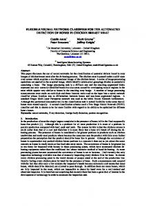
Figure 9: Cell in Laboratory
1 operator ~
*Iarmto
‘ 1 Error recovery
I. -No
I
Yes
c
ip- A put agent to ready, task can
be executed
r-
-4 Retireagent
‘
I
+ I
END
Figure 8: Error Recovery Method
In our laboratory, we have a two-robot assembly system that is dedicated to assemble various types of mechanical parts sent serially into the conveyor belt by the part loader as shown in Figure 9. There are two products currently assembled in this system, and each product has four parts that are assembled by the robot manipulator. The operations include vertical insertion, horizontal insertion, and rotation in assembling with the subassembly fixed at the assembly sites. The parts are fed into the system without a specific order, and the scheduling is made on-line. The cell is equipped with several pieces of hardware that work together to assemble parts, they included two robots, a part loader, several CCD cameras, a conveyor belt, a rotary buffer, and an assembly table with several kinds of fixture. During operations of this assembly system, there are numerous interactions between different coniponents using message passing. For example, when the optical sensor detects a part on the conveyor belt, it
In Figure 8, the main concept on error recovery method in this system is shown. When there are some errors which occur, the Error Manager (EM) will get the description of all these errors and then take the following steps to try to recover these errors. 21 38
signals an interrupt and the associated interrupt service routine sends a message to the PC in charge of overhead camera to take a picture. The PC determines the part’s type and orientation and sends a message to an assigned robot to pick up the part. This is a simple example that could appear in this assembly cell, and there are other similar activties concurrently taking place in the system.
4.2
results are considered extremely useful to expedite the process of creating the shop floor control for any automated production system.
References
CMA Model Specification
C. B. Basnet a:nd J . H. Mize. An object-oriented framework for operating flexible manufacturing systems. In Proceedings of International Confer-
ence o n Object-oriented Manufacturing Systems, Since we have introduced the experiment environment in out labrotory, we want to make an example for demonstrating how to use the Cooperative MultiAgent Architecture model and Task Oriented Flexible Automation Kernel. First, in this section, we will describ the CMA model for this case in detail.
pages 346-351, 1992.
D. M. Dilts, N. F’. Boyd, and H. H. Whorms. The evolution of control architectures for automated manufacturing systems. Journal of Manufacturing Systems, 10(1):79-93, 1991. Larry Jann and ILi-Chen Fu. Flexible control system for robot assembly automation. Master’s thesis, National Taiwan University, Department of Computer Science and Information Engineering, 1994.
Figure 10: Example of Cooperative Multi-A,gent Architecture Figure.10 shows the abstract model view of whole assembly system. There are several agents designed for this cell. Each agent control one hardware in this cell and make a physical link with the hardware (RS232 or one-bit signal port). Agents in this model have their own tasks to perform.
4.3
Results
After setting up all agents and the CMA, specification file. This cell performs smooth assembly tasks without any problems. This control kernel help IUS to establish the full control of the cell. We can get runtime information via GUI of this kernel and perform the recovery procedure easily.
5
Yunho Jeon, Jiingmin Park, Insub Song, YoungJ o Cho, and Sang-Rok Oh. An object-oriented implementation of behavior-based control architecture. In IEEE Int. Conf. on Robotics and Automation, page;s 706-711, 1996. Sanjay B. Joshi, Erik G. Mettala, Jeffrey S. Smith, and Richard A. Wysk. Formal models for control of flexible manufacturing cells: Physical and system model. 11(4):558-570, August 1995. Li Lin, Masatoshi Wakabayashi, and Sadashiv Adiga. Object-oriented modeling and implementation of control software for a robotic flexible manufacturing cell. Robotics and ComputerIntegrated Man,ufactum’ng,ll(1):l-12, 1994. John C. Martin. .Introduction to languages and the theory of computation. McGRAW-HILL, 1991. Michel T. Martinez. Dynamic assembly sequence
- a multi-agent clontrol system. IEEE Symposium on Emerging Technologies and Factory Automation, 2:250-258#,1995.
D. J. Miller ancl 13. C . Lennox. An object-oriented environment fo:r robot system architectures. IEEE Control Systems, 11(2) :14-23, 1991.
Conclusion
In this paper, we have proposed a multi-agent hased model for an intelligent flexible automated production system. Under this model, every piece of equipment is given as an agent and communication among agents are through network using TCP/IP protocol. In order to realize such model, we further develop a task oriented flexible automation kenel (TOFAK:) to establish the necessary message control platform. The present work is successfully demostrated in our 1ntelligent robotic assembly cell in our laboratory. The
2139
J . Borges Soma and F. Lobo Pereira. A general control architeckiire for multiple vehicles. In IEEE Int. Conf. on hlobotics and Automation, pages 692-697, 1996. Steve Vinoski. Corba:integrating diverse application within clicitributed heterogeneous environments. IEEE Communication Magazine, 1.14(2), February 1997.