Engineering, 2009, 1, 140-150 doi:10.4236/eng.2009.13017 Published Online November 2009 (http://www.scirp.org/journal/eng).
Multi-Area Unit Commitment Using Hybrid Particle Swarm Optimization Technique with Import and Export Constraints S. R. P. CHITRA SELVI1, R. P. KUMUDINI DEVI2, C. CHRISTOBER ASIR RAJAN3 1
Department of Electrical Engineering, Anna University, Chennai, India Department of Electrical Engineering, Anna University, Chennai, India 3 Department of Electrical Engineering, Pondicherry Engg.College, Pondicherry, India E-mail:
[email protected],
[email protected],
[email protected] Received January 10, 2009; revised February 21, 2009; accepted February 23, 2009 2
Abstract This paper presents a novel approach to solve the Multi-Area unit commitment problem using particle swarm optimization technique. The objective of the multi-area unit commitment problem is to determine the optimal or a near optimal commitment strategy for generating the units. And it is located in multiple areas that are interconnected via tie lines and joint operation of generation resources can result in significant operational cost savings. The dynamic programming method is applied to solve Multi-Area Unit Commitment problem and particle swarm optimization technique is embedded for computing the generation assigned to each area and the power allocated to all committed unit. Particle Swarm Optimization technique is developed to derive its Pareto-optimal solutions. The tie-line transfer limits are considered as a set of constraints during the optimization process to ensure the system security and reliability. Case study of four areas each containing 26 units connected via tie lines has been taken for analysis. Numerical results are shown comparing the cost solutions and computation time obtained by using the Particle Swarm Optimization method is efficient than the conventional Dynamic Programming and Evolutionary Programming Method. Keywords: Multi-Area Unit Commitment, Evolutionary Programming, Dynamic Programming Method, Particle Swarm Optimization Method
1. Introduction In an interconnected system, the objective is to achieve the most economical generation that could satisfy the local demand without violating tie-line capacity constraints. Due to inter-area transmission constraints, multiarea unit commitment problems (MAUC) are very complicated when compared with single-area unit commitment problems. Research explores that the application of these existing single-area unit commitment to multi-area unit commitment problem is required [1–4]. Furthermore, unit commitment is treated, as separately from the economic dispatch, the linear fuel cost curve may be an expensive operation schedule or a violation of spinning reserve requirements. In multi-area systems, local generations are not equal to local load demands. Areas with lower fuel cost units may generate more
Copyright © 2009 SciRes.
power than their demand and export the excessive energy to the deficient areas; likewise, areas with higher fuel cost units will generate less power than their demand and import the additional energy from other areas with surplus capacity. So, the unit commitment of an area should comply with the local generation as well as the local load demand. References [5–11] provide comprehensive study on multi-area scheduling by relating unit commitment and economic dispatch with tie-line constraints. The following paragraph discusses some of the method, which is adopted in the multi-area unit commitment problem and their implications. There are some drawbacks in implementing the simple priority list method for unit commitment. Although the technique was fast, the results are far from optimal, especially when there are massive on/off transitions. Another difficulty is in which did not deal with topological ENGINEERING
S. R. P. CHITRA SELVI ET AL.
connections in a multi-area system as it considered export/import limitations, which would cause infeasible solutions in many applications. Another approach [6] overcame the previous difficulties. It considered the topological constraints and enhanced unit commitment with economic dispatch .The λ iteration method takes excessive time in finding the optimal solution in large-scale power systems and the speed of the algorithm required some improvement. In the iterative procedure between unit commitment and economic dispatch, there is a need to adjust the unit commitment according to the required area generation. If we use Dynamic Programming Sequential Combination (DP-SC) for unit commitment in a power pool, the search for an optimal solution is very time consuming. If we adopt the priority list method, there may be a solution gap between the resultant schedule and the actual economic operation schedule. If we repeat the process, we may reduce the operation cost, but it will demand a longer execution time. The DP-SC method is used for unit–commitment problem in an interconnected area and particle swarm optimization technique is embedded for assigning generation to each area and modifying the economic dispatch schedule. In this paper, we propose a more efficient approach to the multi-area generation dispatch problem. The proposed technique is used to improve the speed and reliability of the optimal search process. Instead of using λ iteration method in assigning power generation to each area, we used particle swarm optimization to find the optimal allocation of power generation in each area and entire system. Using particle swarm optimization techniques in each area and entire system, we can save time in performing the economic dispatch and operating cost. The meta-heuristic methods [12–19] are iterative techniques that can search not only local optimal solutions but also a global optimal solution depending on the problem domain and time limit. In the meta-heuristic methods, the techniques frequently applied to the UC problem are genetic algorithm (GA), tabu search (TS), evolutionary programming (EP), simulated annealing (SA), particle swarm optimization (PSO), etc. They are general-purpose search techniques based on the principles inspired from the genetic and evolution mechanisms observed in natural systems and populations of living beings. These methods have the advantage of searching the solution space more thoroughly. The main difficulty is their sensitivity to the choice of parameters. In this paper, section one introduces that the mathematical model of the multi-area unit commitment problem. In the problem formulation, DP method is used for committing the unit in each area and λ iteration method is used for importing and exporting power to other area and minimizes the operating cost. Furthermore, tie-line transfer capacities and area spinning reserve requirements are also incorporated in order to ensure system security and reliability. The Reserve-sharing scheme is Copyright © 2009 SciRes.
141
used to enable the area without enough capacity to meet its reserve demand. The objective of MAUC, constraints and conditions of optimal solution are also discussed in this section. Section 3 and 4 explains the EP and PSO algorithm adopted for importing and exporting power to other area. Section 5 gives the results of a case study each one based on a four-area system. A four-area IEEE test power system [6] is then used as an application example to verify the effectiveness of the proposed method through numerical simulations. A comparative study is also made here to illustrate the different solutions obtained based on conventional, EP and PSO methods. Conclusions are presented in the last section.
2. Problem Formulation The cost curve of each thermal unit is in quadratic form k k k 2 k k k F ( Pgi ) ai ( Pgi ) bi ( Pgi ) ci
:$/hr k=1 NA
(1)
The incremental production cost is therefore k
k
k
(2)
2ai Pgi bi
or Pgi
k
k bi
/ 2aik
(3)
The start up cost of thermal unit is an exponential function of the time that the unit has been off X off off i, j S ( X i, j ) Ai Bi (1 e )
(4)
2.1. Multi-Area Unit Commitment The objective function for the multi-area unit commitment is to minimize the entire power pool generation cost as follows: N A t Nk off k k k min [ I i , j F j ( Pg i , j ) I i , j (1 I i , j 1 ) Si ( X i , j 1 ) I , P k 1 j 1 i 1
(5) and the following constraints are to be met for optimization 1) System power balance constraints k k Pg j D j W j ; j 1.......t k k
where
k Pg j k
=
(6)
k Pgi , j k
2) Spinning reserve constraints in each area k k k k k Pgi D j R j E j L j i
;j=1…t
(7)
3) Generation limits of each unit Pg
k k k Pg i , j Pg j j
;i=1…Nk;j=1…t;k=1…NA
(8) ENGINEERING
S. R. P. CHITRA SELVI ET AL.
142
4) Minimum Up and Down time constraints off on ( X i , j 1 Ti ) * ( I i , j 1 I i , j ) 0
(9)
off off ( X i , j 1 Ti ) * ( I i , j 1 I i , j ) 0
(10)
To decompose the problem in Equation (5), it is rewritten as t min [ F ( Pgi , j )] P j 1
(11)
where Nk k k F ( Pgi , j ) F ( Pg i , j ) k 1
(12)
subject to the constraints of Equation (6) and (8) and following constraints. 5) Export/Import constraints k k k Pg i. j D j E j max i
(13)
k k k Pgi , j D j L j max i k
(14)
k k E j Lj Wj 0 i k
(15)
6) Area generation limits k k k Pgi , j Pgi R j i i k k Pgi , j Pgi i i
Each
F k ( Pgik, j )
; k =1… N A ; j 1... t
; k =1 N A ; j 1... t for
k 1..., N A
the operation cost. k k k k Pg j D j E j L j
where
(17)
tion (7) to change accordingly and redefine Equation(18). In this study, the iterative equal incremental cost method ( method) was used to solve Equation (11) and serve as a coordinator between unit commitments in various areas. With the iteration, the system would operate at an optimal point if for each unit is equal to a system incremental cost sys .Units may operate in one of the following modes when commitment schedule and unit generation limits are encountered: 1) Coordinate mode: The output of unit i is determined by the system incremental cost
2.2. Multi-Area Economic Dispatch The objective of Multi-area Economic Dispatch (MAED) is to determine the allocation of generation of each unit in the system and power exchange between areas so as to minimize the total production cost. The lamda–iteration
(20)
min,i sys max,i
2) Minimum mode: Unit i generation is at its minimum level. (21)
min,i sys
3) Maximum mode: Unit i generation is at its maximum level. (22)
max,i sys
(18)
Subject to constraints of Equation (7), (9-10) and initial on/off condition of each unit. The multi-area unit commitment problem is solved by Dynamic Programming Sequential Combination (DP-SC) method to form the optimal generation scheduling approach. Among the available generating units in the interconnected multi-area system and the proposed method sequentially identifies, via a procedure that resembles bidding, the most advantageous units to commit until the multi-area system obligations are fulfilled and this method has been explained [13].
N k k Pg j i k1 Pg i , j
with the economic dispatch within the pool , changes of Pg kj will cause the spinning reserve constraint of Equa-
is represented in the
off k k k min [ I i , j Fi ( Pg i , j ) I i , j (1 I i , j 1 ) Si ( X i , j ) I ,P i
(19)
Since the local demand D kj is determined in accordance
(16)
form of schedule tables, which is the solution of the mixed variables optimisation problem
Copyright © 2009 SciRes.
method is implemented in the MAED to include area import and export constraints and tie-line constraints [15] The objective is to select sys every hour to minimize
4) Shut down mode: Unit i is not in operation,
Pg i
= 0.
Besides limitations on individual unit generations, in a multi-area system, the tie-line constraints in Equation (9), (10) and (14) are to be preserved. The operation of each area could be generalized into one of three modes as follows: Area coordinate mode
k
sys
(23)
k k k k k D j Lmax Pi , j D j Emax i
(24)
k k k k Lmax Pgi , j D j Emax i
(25)
or
a. Limited export mode When the generating cost in one area is lower than the cost in the remaining areas of the system, that area may generate its upper limit according to Equation (13) or (16), therefore,
ENGINEERING
S. R. P. CHITRA SELVI ET AL.
k
143
(26)
sys
k
is the optimal equal incremental cost which satisfies the generation requirement in each area k. b. Limited import mode An area may reach its lower generation limit according to Equation (14) or (17), because of the higher generation costs.
k
(27)
min sys
The proper generation schedule in multi-area will result by satisfying tie-line constraints and minimizing the system generation cost.
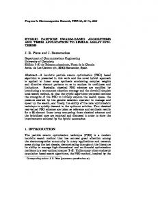
2.3. Tie-Line Flow of Four Areas An economically efficient area may generate more power than the local demand, the excess power will be exported to the other areas through the tie-lines. As shown in Fig. 1, assume area 1 has excess power, the line flows would have directions from area 1 to other areas, and the maximum power generation for area 1 would be the local demand in area 1 plus the sum of all the tie-line capacities connected to area 1. If we fix the area 1 generation at its maximum level, then the maximum power generation in area 2 could be calculated in a similar way to area 1. Since tie-line imports power at its maximum capacity, this amount should be subtracted from the generation limit of area 2. According to the system power balance equation some areas must have a power generation deficiency, and require generation imports. The minimum generation level of these areas is the local demand, minus all the connected tie-line capacities. If any of these tie lines is connected to an area with higher deficiencies, then the flow directions should be reversed. The tie-line flow details of four area and directional matrix were presented in [9]. Directional matrix: It indicates power flow direction from one area to another area. Dl ,k [ 1 when line flows from l to k l >k [ -1 when line flows from k to l Dl ,l 0, Dl .k Dk ,l initial
Dl .k
are zero
3. Evolutionary Programming Method
Figure 1. Flow chart for evolutionary algorithm.
ciple to evolution strategy (ES), in that normally distributed mutations are performed in both algorithms. Both algorithms encode mutation strength (or variance of the normal distribution) for each decision variable and a self-adapting rule is used to update the mutation strengths. Several variants of EP have been suggested (Fogel, 1992).
3.2. Evolutionary Programming Algorithm The original Evolutionary Programming involved evolving populations of extending algorithms to develop artificial intelligence [17]. In this technique a strong behavioral link is sought between each parent and its offspring, at the level of the species.Fig.1 shows e general scheme of the EP algorithm.
3.1. Introduction EP is a mutation-based evolutionary algorithm applied to discrete search spaces. D. Fogel (Fogel, 1988)] extended the initial work of his father L. Fogel (Fogel, 1962) [15–18] for applications involving real-parameter optimization problems. Real-parameter EP is similar in prin Copyright © 2009 SciRes.
3.3. Implementation of Evolutionary Algorithm for Multi-Area Unit Commitment Problem Step (1): Read in unit data, tie-line data, demand profile. Step (2): Perform the dynamic programming to get the initial commitment schedule for each area. ENGINEERING
S. R. P. CHITRA SELVI ET AL.
144
Step (3): Initialization of parent population. The initial parent population of size Np is randomly generated for committed unit in each area: 1) To generate the initial parent population
kp kp I p ( p g1 ....... p gN )]; k 1, 2, 3, 4 & p 1, 2... N p ;
(29) 3) To calculate the start up cost for each population using Equation (4) 4) To calculate the production cost Production (30)
5) To calculate the fitness function for each parent of population Nk kp K K k FP FC P SC P K ( PGi D j ) i 1
(32)
generated as KO KO 2 K Pgi Pgi N (0, Pgi ); i 1, 2...... N
Similarly all
Pgi
is generated for all areas subjected to
ko ko Pg i =Pg i ,min ; if Pg i < Pg i ,min ko KO Pg i =Pg i ,max ; if Pg i > Pg i ,max
(33)
N (0, 2 ) represents a normal random variable with zero
mean and standard deviation Pg ( Fpi / Fmax ) ( ij ,max ij ,min ) i
where is scaling factor,
F pi
(34)
is the value of fitness
function corresponding to I i and Fmax is the maximum fitness function value among parent population 2) To compute the fitness value corresponding to each offspring using Equation (31) Step (5): (competition and selection). The 2I individuals compete with each other for selection using Equation (6). A weight value Wi is assigned to each individual as follows:
Copyright © 2009 SciRes.
(36)
where ft is the fitness of the i competitor randomly selected from 2I individuals and u is a uniform random number ranging over [0, 1].While computing the weight for each individual, it is ensured that each individual is selected only once from the combined population. Even though relative fitness values are used during the process of mutation, competition and selection, it leads to slow convergence. This is because the ratio f t /( ft f i ) is always around 0.5 without uniform distribution between 0 and 1.Hence, the following strategy is followed in this paper to assign weights: Wt {1, if ft /( ft fi ) 0.5
(37)
Wt {0, otherwise
(31)
The values of the penalty factor is chosen such that if there are any constraints violations then the fitness function value corresponding to that parent will be ineffective. Step (4): Mutation 1) To generate an offspring population Io of size from Np from each parent Ip ko ko I O [( Pg1 ........Pg N ); k 1, 2, 3, 4; 0 1..... N p
Wt {0, otherwise th
kp 2 kp K FC p [( a ( Pg1 ) b ( Pg1 ) c ); k 1, 2, 3, 4 & p 1, 2... N p
k k FC p SC p
(35)
u ( ft / ft fi )
Wt {1, if
(28)
2) To calculate the fuel cost for each population using Equation (1)
cost=
I Wi Wt t 1
This weight assignment is found to yield proper selection and good convergence. When all the 2I individuals obtain their weights, they are ranked in descending order and the first I individuals are selected as parents along with their fitness values for next generation. Steps (4) and Steps (5) are repeated until there is no appreciable improvement in the minimum fitness value. Step (6): Optimum generation schedule is obtained for four areas using minimum fitness value. Check area generation with local demand Step (7): Areas with lower fuel cost may export the excessive generation to other areas with higher fuel cost (deficiency areas) with tie line limit.
4. Particle Swarm Optimization Particle swarm optimization (PSO) is inspired from the collective behavior exhibited in swarms of social insects [19]. It has turned out to be an effective optimizer in dealing with a broad variety of engineering design problems. In PSO, a swarm is made up of many particles, and each particle represents a potential solution (i.e., individual). A particle has its own position and flight velocity, which are adjusted during the optimization process based on the following rules: Vi
P 1
Vi
P
KP KP KP KP C1 rand () ( Pbi Pi ) C2 rand () ( Pgi Pi )
(38) Pi
KP
Pi
KP
Vi
P 1
(39)
where V is the updated particle velocity in the next t1 iteration, Vt is the particle velocity in the current iteration,
is the inertia dampener which indicates the im-
ENGINEERING
S. R. P. CHITRA SELVI ET AL.
pact of the particle’s own experience on its next movement, C rand represents a uniformly distributed num1
ber within the interval [0, c1], which reflects how the neighbours of the particle affects its flight, PbiKP is the neighbourhood best position, Vi P is the current position of the particle and C rand represents a uniformly 2
distributed number within the interval [0, c2], which indicates how the particle trusts the global best position, PgiKP is the global best position, and Vi P 1 is the updated position of the particle. Under the guidance of these two updating rules, the particles will be attracted to move towards the best position found thus far. That is, the optimal solutions can be sought out due to this driving force. The major steps involved in Particle Swarm Optimization approach are discussed below: 1) Initialization The initial particles are selected randomly and the velocities of each particle are also selected randomly. The size of the swarm will be (Np x n), where Np is the total number of particles in the swarm and ‘n’ is the number of stages. 2) Updating the Velocity The velocity is updated by considering the current velocity of the particles, the best fitness function value among the particles in the swarm. The velocity of each particle is modified by using Equation (28) The value of the weighting factor is modified by following Equation (40) to enable quick convergence. max (max min ) / itermax iter
(40)
The term < 1 is known as the “inertia weight” and it is a friction factor chosen between 0 and 1 in order to determine to what extent the particle remains along its original course unaffected by the pull of the other two terms. It is very important to prevent oscillations around the optimal value. 3) Updating the Position The position of each particle is updated by adding the updated velocity with current position of the individual in the swarm
4.1. Algorithm of Particle Swarm Optimization The step by step procedure to compute the global optimal solution is followed. Step (1): Initialize a population of particles with random positions and velocities on d dimensions in the problem space. Step (2): For each particle, evaluate the desired optimization fitness function in the variables. Step (3): compare particles fitness evolution with particles Pbest . If current value is better then Pbest , then Copyright © 2009 SciRes.
145
set Pbest value equal to the current value, and the Pbest location equal to the current location in the dimensional space. Step (4): Compare fitness evaluation with the populations overall previous Pbest . If current value is better than gbest , then reset to the current particles array index and value. Step (5): Change the velocity and position of the particle according to Equations (38) and (39) respectively. Step (6): Loop to step 2 until a criterion is met, usually a sufficiently good fitness or a maximum number of iterations.
4.2. Implementation of Particle Swarm Optimization Algorithm for Multi-Area Unit Commitment The various steps of the PSO algorithm are given below for solving multi area unit commitment problem: Step (1): Read in unit data, tie-line data, load demand profile. Step (2): Perform the dynamic programming to get the initial commitment schedule for each area. Step (3): Initialization of particle .The initial particle of size Np is generated randomly for committed unit in each area : 1) Calculate the initial particle population kp kp I p [( P1 .....P2 ); k 1, 2, 3, 4 : p 1..... N p
(41)
2) Calculate the fuel cost for each particle using Equation (1) kp 2 kp k FC p [( a ( P1 ) b ( P1 ) c ); k 1, 2, 3, 4; p 1, 2... N p
(42)
3) Calculate start up cost of each particle using Equation (4) 4) Calculate the production cost Production Cost = FCkp SC kp
(43)
5) Calculate the fitness function for each particle of population Nk kp k k k Fp FC p SC p k ( Pi D j ) i 1
(44)
6) To calculate the Pbest by using fitness function values, If current value is better then previous Pbest ,then set Pbest value equal to the current value and compute gbest if current value is. Step (4): Updating the Velocity The velocity is updated by considering the current velocity of the particles, the best fitness function value among the particles in the swarm using following Equation (45). Vi
P 1
Vi
P
KP KP KP KP C1 rand () ( Pbi Pi ) C2 rand () ( Pgi Pi )
(45) ENGINEERING
S. R. P. CHITRA SELVI ET AL.
146
where is weight factor, The weight is computed using Equation (40) Step (5): Updating the particle position The position of each particle is updated by adding the updated velocity with current position of the individual in the swarm. Pi
KP
Pi
KP
Vi
P 1
(46)
The steps described in sub Sections 3 to 5 are repeated until a criterion is met, usually a sufficiently good fitness the maximum generation count is reached. Step (6): Optimum generation schedule is obtained for four area using gbest particle. Check area generation with local demand. Step (7): Areas with lower fuel cost may export the excessive generation to areas with higher fuel cost (deficiency areas) with tie line limit
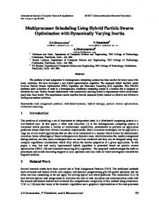
Figure 2. Topological connections of four areas.
5. Test System and Simulation Results The proposed MAUC algorithm has been implemented in C++ environment and tested extensively. Test results of a multi-area system are presented in this section. All simulations are performed in a PC with Intel processor (1.953 GHz) and 1012 MB of RAM. As shown in Figure 2, a sample multi-area system with four areas, IEEE reliability test system, 1996 data in [9], are used to test the speed of solving the multi-area UC and ED for a large-scale system with import/export capability and tie line capacity constraints. In the sample multi-area system, each area consists of 26 units. The total number of units tested is 104, and their characteristics are presented in [9]. There are some identical thermal units also located in each area. The system contains five tie lines four area interconnections as shown in Figure 4, and area one is the reference area. Figure 3 shows the modified same load demand profile forecast used in all four areas. The assumptions described in tie line capacity constraint are applied to the simulations. The four areas have the same load demand profiles. As the 1oad demand is same in these four areas, the economical area will generate more power than expensive areas. Figure 3 gives the changes in area 1 power generation, committed unit capacities, unit commitment pattern of hour 7am and spinning reserve requirement of area 1 is 400MW, because the available unit capacities are not more than the power generation plus the spinning reserve. This phenomenon proves that the available capacity should comply with the area power generation instead of the local load demand. The systems 1oad demand is 6800 MW, so area 1 generation increases steadily while that of area 2, 3 decreases. The incremental cost of area 2, 3 is higher than
Copyright © 2009 SciRes.
Figure 3. Load pattern for all four –area.
Figure 4.Tie-line flow pattern for 7am.
that of the other two areas since the tie flows to area 2, 3 are at their maximum capacities. This manifests that the proposed method considers tie-line limits effectively. Table I shows that parameter used in EP and PSO method. Table 2, 3, 4 and Table V shows comparison result of DP and EP, PSO. Figure 4 and 5 shows the convergence characteristics for multi-area obtained using proposed methodology. Table 2 shows that the total production cost is obta-
ENGINEERING
S. R. P. CHITRA SELVI ET AL. Table 1. Parameter used in EP & PSO. Parameter
EP
PSO
Population size(p)
10
10
0.03
-
Mutation scaling
factor(β)
Penalty factor(k1)
10000
Table 2. Operating cost of DP method. Hours (24)
1000 0
Maximum Generation
500
500
Learning factor(c1,c2)
-
2
1 2 3
ined by using conventional method. Table 3 and 4 shows that the total production cost is obtained for ten iterations by using EP and PSO method. Figure 4 gives the plot of EP average performance from 500 runs. Figure 5 gives the plot of number of iteration versus the time taken to complete those iterations and the maximum production cost obtained under each iteration using PSO method. As we indicated in the paper, the PSO algorithm has also proved to be an efficient tool for solving the multi –area unit commitment with economic dispatch problem. There is no obvious limitation on the size of the problem that must be addressed, for its data structure is such that the search space is reduced to a minimum; no “relaxation of constraints” is required; instead, populations of feasible solutions are produced at each generation and throughout the evolution process. The main advantages of the proposed algorithm are speed. The proposed PSO approach was compared to the related methods in the references indented to serve this purpose, such as the DP with a zoom feature, and the EP approaches. In addition, with the use of PSO method, the status is improved by avoiding the entrapment in local minima. By means of stochastically searching multiple points at one time and considering trial solutions of suc cessive generations, the PSO approach gives global minima instead of entrapping in local optimum solutions. The PSO method obviously displays a satisfactory performance with respect to the quality of its evolved solutions and to its computational requirements. The final result of PSO would save 0.12% $2865.4 is compared with the solution obtained by the conventional method but it would require 33 seconds to complete the computation .So, the EP method is reduced the operating cost by 0.08 % than the conventional method but it requires 36 seconds to complete this computation .From these results, the PSO method had less total cost and consumed also less CPU time compared to other method.
6. Conclusions Application of PSO is a novel approach in solving the MAUC problem. Results demonstrate that PSO is a very competent method to solve the MAUC problem. PSO
Copyright © 2009 SciRes.
147
4 5 6 7 8 9 10 11 12 13 14 15 16 17 18 19 20 21 22 23 24 Total cost
Area-1 (26 Unit)
Area-2 (26 Unit)
Area-3 (26 Unit)
Area-4 (26 Unit)
37115.330 08 24747.960 94 27995.107 42 29576.867 19 29347.660 16 36118.037 11 40483.162 11 39248.855 47 38728.734 38 37215.339 84 37193.468 75 38310.472 66 33225.353 52 31623.279 30 30595.626 95 36312.250 00 36925.175 78 35682.320 31 35682.320 31 35682.320 31 38042.478 52 30190.896 48 30923.708 98 30202.210 94 821168.93 75
24115.5214 8 23137.6396 5 23137.6396 5 18274.3261 7 18329.3261 7 18329.3261 7 28104.1445 3 32917.4687 5 34865.2382 8 32205.3750 0 32205.3750 0 32205.3750 0 34149.0293 0 37085.8281 3 33172.8613 3 32989.6523 4 32989.6523 4 39459.6250 0 39903.0585 9 32114.9414 1 29387.7168 0 15095.1718 8 18398.0820 3 15198.7812 5 677771.156 3
28331.2265 6 22994.8997 4 23701.2568 4 26151.8378 9 25595.4296 9 23799.5097 7 21999.5986 3 19852.8554 7 18245.3730 5 22093.5957 0 20244.0820 3 20992.8925 8 18152.8222 7 17146.9394 5 17991.4726 6 22492.5781 3 23769.5800 8 27589.7597 7 23860.8418 0 21973.3906 3 19907.5390 6 21115.4316 4 19966.2128 9 19815.6132 8 527784.731 2
22042.12 500 19289.81 836 19175.97 998 18397.77 637 18698.77 344 19705.58 106 24891.27 832 21117.69 727 21253.34 180 24255.43 945 23298.57 031 21298.69 336 26442.17 773 25955.68 945 23682.43 359 25305.94 336 25383.72 656 19501.75 391 22304.66 016 15999.40 332 20248.24 805 21807.76 953 22309.07 813 18294.49 805 520660.4 566
generates better solutions than the other methods, mainly because of its intrinsic nature of updates of positions and velocities. The reason is due to the hourly basis solution. This is somehow similar to the “divide and conquer” strategy of solving a problem. Owning to this
ENGINEERING
S. R. P. CHITRA SELVI ET AL.
148 Table 3. Opearting cost of EP method. Hour -s (24)
1 2 3 4 5 6 7 8 9 10 11 12 13 14 15 16 17 18 19 20 21 22 23 24 Total cost
Area-1 Area-2 Area-3 Area-4 Table 4. Operating cost of PSO method (26 Unit) (26 Unit) (26 Unit) (26 Unit)
37112.330 08 24741.960 94 27988.107 42 29566.867 19 29337.660 16 36108.037 11 40473.162 11 39238.855 47 38718.734 38 37202.339 84 37183.468 75 38296.472 66 33212.353 52 31607.279 30 30578.626 95 36281.250 00 36919.175 78 35662.320 31 35662.320 31 35662.320 31 38032.478 52 30177.896 48 30913.708 98 30182.210 94 820859.93 75
24093.521 48 23127.639 65 23127.639 65 18254.326 17 18309.326 17 18309.326 17 28084.144 53 32897.468 75 34841.238 28 32185.375 00 32185.375 00 32185.375 00 34129.029 30 37063.828 13 33152.861 33 32969.652 34 32969.652 34 39439.625 00 39893.058 59 32094.941 41 29365.716 8 15065.171 88 18387.082 03 15168.781 25 677300.15 62
28311.2265 6 22964.8997 4 23681.2568 4 26121.8378 9 25572.4296 9 23789.5097 7 21975.5986 3 19822.8554 7 18215.3730 5 22063.5957 0 20224.0820 3 20972.8925 8 18132.8222 7 17126.9394 5 17981.4726 6 22462.5781 3 23749.5800 8 27569.7597 7 23839.8418 0 21943.3906 3 19887.5390 6 21073.4316 4 19946.2128 9 19796.6132 8 527225.739 6
Hours (24)
22002.12500 19259.81836
Area-1 (26 Unit)
Area-2 (26 Unit)
Area-3 (26 Unit)
Area-4 (26 Unit)
37096.33008
24048.52148
24514.96094
23004.63965
27980.10742
23004.63965
29568.86719
18286.32617
29387.66016
18286.32617
35838.03711
18286.32617
40497.16211
28043.14453
39228.85547
32977.46875
38648.73438
34802.23828
37229.33984
32191.37500
37184.46875
32191.37500
38294.47266
32191.37500
33200.35352
34120.0293
31630.27930
37051.82813
30578.62695
33162.86133
36281.25000
32960.65234
36949.17578
32960.65234
35766.32031
39439.62500
35766.32031
39811.05859
35766.32031
32081.94141
38122.47852
29353.71680
30177.89648
15065.17188
31583.70898
18379.08203
29449.21094
15159.78125
820740.9375
676860.1562
28309.226 56 22910.899 74 23674.256 84 26111.837 89 25578.429 69 23769.509 77 21945.598 63 19815.855 47 18245.373 05 22063.595 70 20212.082 03 20979.892 58 18127.822 27 17124.939 45 17978.472 66 22459.578 13 23748.580 08 27569.759 77 23839.841 8 21943.390 63 19897.539 06 21073.431 64 19966.212 89 19816.613 28 527162.73 96
21998.125 00 19251.818 36 19145.979 98 18374.776 37 18671.773 44 19673.581 06 24858.278 32 21081.697 27 21201.341 80 24199.439 45 23272.570 31 21262.693 36 26401.177 73 25928.689 45 23631.433 59 25277.943 36 25365.726 56 19465.753 91 22243.660 16 15968.403 32 20208.248 05 21791.769 53 22270.078 13 18211.498 05 519756.45 65
1 2
19151.97998 3 18367.77637 4 18678.77344 19683.58106 24861.27832 21087.69727 21223.34180
5 6 7 8 9
24205.43945
10
23278.57031
11
21268.69336
12
26412.17773
13
25920.68945
14
23642.43359
15
25286.94336
16
25353.72656
17
19471.75391 22274.66016 15969.40332 20218.24805 21797.76953
18 19 20 21 22 23
22279.07813 18254.49805
24 Total cost
519950.4565
hourly solution, the complexity of the search is greatly reduced. The total objective function is the sum of objectives and constraints, which are fuel cost, start-up cost, Copyright © 2009 SciRes.
Table 4. Operating cost of PSO method.
spinning reserve, power demand, tie-line limit, and import and export constraints. For a better solution, generated powers by N unit of generators and K areas, tie –line limits are constantly checked so that feasible particles can meet the power demand .This reduces the pressure of ENGINEERING
S. R. P. CHITRA SELVI ET AL.
149
[3] F. Gao, “Economic dispatch algorithms for thermal unit system involving combined cycle units,” IEEE and Gerald Bushel IEEE Lowa State University Ames, IA, USA, IEEE Transaction on Power Systems, pp. 1066–1072, November 2003.
[4] E. Fan, X. H. Guan, and Q. Z. Zhai, “A new method for unit commitment with ramping con straints,” IEEE Transaction on Power Systems, March 2001.
[5] H. T. Yang and C. L. Huang, “Evolutionary programming based economic dispatch for units with non-smooth fuel cost functions,” IEEE Transactions on power system, Vol. 11, No. 2, pp. 112–118, 1996. Figure 4. Convergence characteristics of EP method.
[6] Z. Ouyang and S. M. Shahidehpour, “Heuristic multi-area unit commitment with economic dispatch,” IEEE Proceedings, Vol. 138, No. 3, pp. 242–252, 1991.
[7] C. L. Tseng, “Multi-area unit commitment for large scale power system,” IEEE Proceedings - Generation and Distribution, Vol. 145, No. 41, pp. 415–421, 1999.
[8] C. Wang and M. Shahidehpour, “A decomposition approach to non-linear multi-area generation scheduling with tie-line constraints using expert systems,” IEEE Transactions on Power System, Vol. 7, No. 4, pp. 1409 –1418, 1992.
[9] C. K. Pang, G. B. Sheble, and F. Albuyeh, “Evaluation of
Figure 5. Convergence characteristics of PSO method. Table 5. Comparison of DP, EP, PSO method.
dynamic programming based methods and multiple area representation for thermal unit commitments,” IEEE Transactions on Power Apparatus System, Vol. 100, No. 3, pp. 1212–1218, 1981.
[10] F. N. Lee, J. Huang, and R. Adapa, “Multi-area unit commitment via sequential method and a DC power flow network model,” IEEE Transactions on Power System, Vol. 9, No. 1, pp. 279– 284, 1994.
[11] C. Yingvivatanapong, W. J. Lee, and E. Liu, “Multi-area power generation dispatch in competitive markets,” IEEE Transactions on Power Systems, pp. 196–203, 2008.
[12] U. B. Fogel, “On the philosophical differences between the constraint violation of the total objective function. Finally, the result obtained from the simulation is most encouraging in comparison to the best-known solution so far. In the future work, the power flow in each area can be considered to further increase the system security. Other issues such as transmission losses, transmission costs, call and put options policies between and bilateral contract areas can also be considered to reflect more realistic situations in MAUC problems.
7. References [1] S. Salam, “Unit commitment solution methods,” Proceedings of World Academy of Science, Engineering and Technology, Vol. 26, December 2007.
[2] B. Lu and M. shahidehpour, “Short term scheduling of
evolutionary algorithms and genetic algorithms,” IEEE Proceedindings in Second Annual Conference on Evolutionary Programming, pp. 23–29, 1993.
[13] T. Biick and H. P. Schwefel, “An overview of evolutionary algorithm for parameter optimization,” Evolutionary Computation, Vol. 1, No. 1, pp. 1–24. 1993.
[14] C. C. Asir Rajan and M. R. Mohan, “An evolutionary programming-based tabu search method for solving the unit commitment problem,” IEEE Transactions on Power System, Vol. 19, No. 1, pp. 577–585, 2004.
[15] D. Srinivasan, F. Wen, and C. S. Chang, “A survey of applications evolutionary computing to power systems,” IEEE Proceedings, USA, pp. 35–41, 1996.
[16] J. Kennedy, “The particle swarm: Social adaptation of knowledge,” Proceedings in International Conference on Evolutionary Computation, Indianapolis, pp. 303–308, 1997.
combined cycle units,” IEEE Transaction on Power System, Vol. 19, pp. 1616–1625, August 2004. Copyright © 2009 SciRes.
ENGINEERING
S. R. P. CHITRA SELVI ET AL.
150
Appendix A Nomenclature D kj Lkj E kj Iik, j Irlist
Total load demand in area k at jth hour Total import power to area k at jth hour Total export power to area k at jth hour Commitment state (1 on, 0 for off)
i
List of committed units ascending priority order Index for units Index for time Lagrangian multiplier for unit
sys
Lagrangian multiplier for entire system
N
Total number of areas
i j
N
O
A k
plist
Pg kj Pgik
Pgik
Upper limit of power generation of unit i in area k
Pgik, j
Power generation of unit i in area k at j th hour
R kj
Spinning reserve of area k at j th hour
S kj
Total commitment capacity for area k at j th hour
SD kj
Tion off Ti
Total system demand at j th hour t Total time span in hours Minimum up time of unit i Minimum down time of unit i
i
Time constant in start up cost function for
List of uncommitted units in descend-
Wj
unit i Net power exchange with outside systems
ing order
on / off X i, j
Time duration for which unit i has been
Total number of units in area K
Power generation of area k at jth hour
on/off at jth hour
Lower limit of power generation of unit i in area k
Copyright © 2009 SciRes.
ENGINEERING