Modeling multi-core systems for formal verification of par- allel algorithm .... Diagram Representation of Intel Ticket Spinlock Model well as the number of ...
IEEE TRANSACTIONS ON PARALLEL AND DISTRIBUTED SYSTEMS, VOL. X, NO. Y, MONTH 2009
1
Multi-Core Systems Modeling for Formal Verification of Parallel Algorithms Mathieu Desnoyers, Paul E. McKenney, Michel R. Dagenais
Abstract—Modeling parallel algorithms at the architecture level permits to explore side-effects of weak ordering performed by modern processors. Formal verification of such models with model-checking can ensure that algorithm guarantees will hold even in the presence of the most aggressive compiler and processor optimizations. This paper proposes a virtual architecture to model the effects of such optimizations. It first presents the OoOmem framework to model out-of-order memory accesses. It then presents the OoOisched framework to model the effects of out-of-order instruction scheduling. These two frameworks are explained and tested using weaklyordered memory interaction scenarios known to be affected by weak ordering. Then, modeling of user-level RCU (Read-Copy Update) synchronization algorithms is presented. It uses the virtual architecture proposed to verify that the RCU guarantees are indeed respected. Index Terms—C.0.d Modeling of computer architecture < 0. General < C. Computer System Organization, C.1.2.g Parallel processors < C.1.2 Multiple Data Stream Architectures (Multiprocessors) < C.1 Processor Architectures < C. Computer System Organization, D.1.3. Concurrent Programming < D.1 Programming Techniques < D. Software/Software Engineering, D.2.4.d Formal Methods < D.2.4 Software/Program Verification < D.2 Software Engineering < D. Software/Software Engineering, D.2.4.e Model Checking < D.2.4 Software/Program Verification < D.2 Software Engineering < D. Software/Software Engineering, D.4.1.f Synchronization < D.4.1 Process Management < D.4 Operating Systems < D. Software/Software Engineering D.4.5.f Verifcation < D.4.5 Reliability < D.4 Operating Systems < D. Software/Software Engineering ”, which indicates a condition always fulfilled. This lets the statements following the “->” execute unconditionally. Line 7 ends with a very important keyword: atomic. It precedes a sequence of statements, contained within brackets, which is considered as indivisible. They are therefore executed in a single execution step, similarly to an atomic instruction executed by a processor. Lines 19–22 contain the unlock function. Lines 24–33 contain the body of the processes, which takes a spinlock, increments and decrements the reference count, and releases the lock in an infinite loop. Two instances
IEEE TRANSACTIONS ON PARALLEL AND DISTRIBUTED SYSTEMS, VOL. X, NO. Y, MONTH 2009 byte lock = 0; byte refcount = 0;
UNLOCKED skip
inline spin_lock(lock) { do :: 1 -> atomic { if :: lock -> skip; :: else -> lock = 1; break; fi; } od; }
ATOMIC TRY LOCK skip (lock == 0) STEP invariant
inline spin_unlock(lock) { lock = 0; }
TAKE LOCK lock = 1
proctype proc_X() { do :: 1 -> spin_lock(lock); refcount = refcount + 1; refcount = refcount - 1; spin_unlock(lock); od; }
STEP++ STEP++
init { run proc_X(); run proc_X(); }
Fig. 1.
Promela Model for PowerPC Spinlock
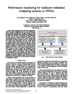
of the process are run upon initialization by init at Lines 35– 39. This Promela code is represented by the diagram found in Figure 2. Each node represents a Promela statement. A name is added to most nodes to make interpretation easier. Each node contains a Promela statement. Arrows connecting the nodes represent how the model-checker can move between nodes. Some require conditions to be active, e.g. (lock == 1), to allow moving to the target node. The STEP++ statements on the arrows represent that the execution counter is incremented. A concurrent process may run between different steps, but not while STEP stays invariant. The latter scenario happens in the ATOMIC box, which represents the atomic sequence of statements. Safety of this locking primitive is successfully verified by the Spin model-checker by verifying that the reference count value is never higher than 1. This is performed by prepending #define refcount_gt_one (refcount > 1) to the model and by using the following LTL formula. PowerPC spinlock safety is verified by the LTL claim: � G ¬ refcount gt one However, one major downside of this spinlock implementation is its lacks of fairness. A CPU always acquiring the same spinlock in a loop could effectively starve other CPUs. This can be verified using the following LTL formula: � G F (¬ np )
(lock == 1) STEP++
STEP++
CRITICAL SECTION
1 2 3 4 5 6 7 8 9 10 11 12 13 14 15 16 17 18 19 20 21 22 23 24 25 26 27 28 29 30 31 32 33 34 35 36 37 38 39
3
ref++
STEP++
ref−−
STEP++
UNLOCK lock = 0
Fig. 2.
Diagram Representation of PowerPC Spinlock Model
The keyword np_ has a special meaning: it is true if all system states do not correspond to progress states. We modify the code from Figure 1 to insert such progress states: this involves separating the process body in two different definitions to add a progress: keyword within the infinite loop in one of them. Using the Spin verifier weak fairness option lets it detect non-progress cycles involving more than one process. This corresponds to starvation of a process by one or more other processes. Ticket spinlocks used for the Intel spinlock implementation found in Linux correct the fairness problem identified in the PowerPC architecture. The Promela implementation is omitted due to space considerations, but the state diagram is presented at Figure 3. The new elements added to this graphs are the LOW_HALF() and HIGH_HALF() primitives, which select half lower and upper bits of the lock, respectively. The Spin model-checker verifies that this model is safe and fair, under certain conditions. Changing the number of bits available for the low and high halves of the ticket lock as
IEEE TRANSACTIONS ON PARALLEL AND DISTRIBUTED SYSTEMS, VOL. X, NO. Y, MONTH 2009
UNLOCKED skip STEP++
ATOMIC READ TICKET ticket = HIGH_HALF(lock)
STEP invariant
STEP++ INC TICKET HIGH_HALF(lock)++
STEP++ WAIT TICKET skip
CRITICAL SECTION
(LOW_HALF(lock) == ticket) STEP++
(LOW_HALF(lock) != ticket) STEP++
ref++
STEP++
ref−−
STEP++
UNLOCK LOW_HALF(lock)++
Fig. 3.
Diagram Representation of Intel Ticket Spinlock Model
well as the number of processes shows that fairness is only ensured when the number of processes fits in the number of bits available for each half. IV. W EAKLY-O RDERED M EMORY F RAMEWORK A. Architecture Modeling out-of-order memory accesses performed by processors at a level consistent with their hardware implementation is important to enable accurate modeling of sideeffects that can be caused by missing memory barriers in synchronization algorithms. The bugs within this category are hard to reproduce, mainly because they are dependent on the architecture, execution context and timing between the processors. Therefore, testing the implementation might not be sufficient to certify the absence of bugs. To model an algorithm including the effects of the memory barriers required on various architectures, or more importantly lack thereof, we choose to create a virtual architecture performing the most aggressive memory reordering. The Alpha 21264 seems to be an especially interesting architecture with respect to reordering, given its ability to reorder dependent loads (14; 15). It also reorders loads after stores, stores after
4
loads, loads after loads and stores after stores. Even atomic operations can be reordered with respect to loads and stores. The Alpha architecture can reorder dependent loads in addition to other memory accesses due to the design of its caches. These are are divided into banks, which can each communicate with main memory. If the channel between a bank and memory is saturated, the updates of the less busy channels could reach their destination before loads or stores initiated earlier. Such extremely weak ordering can therefore cause any sequence of loads and stores to different addresses, including dependent loads, to be perceived in a different order from the point of view of another processor. Indeed, when memory content changes, in-cache view updates are not guaranteed to reach the cache-lines in the same order the main memory stores appear. We name the weak memory ordering part of our virtual architecture OoOmem, where OoO stands for Out-of-Order. It models the exchanges between CPU cache-lines and main memory. To model the worse possible case, each variable belongs to a different cache-line and there is only one cacheline per bank. These cache-lines are therefore free to be updated (or not) with main memory between each instruction execution. Each CPU is modeled as a Promela process. Each variable is represented with a main memory entry, a per-CPU entry and a per-CPU dirty flag. Operations and accesses to these memory entries are performed through Promela macros created as part of the OoOmem framework to facilitate manipulation of the variables. We call these the “primitives” of the OoOmem framework. For each cache-local variable, the ooo_mem() primitive models the case where it is updated as well as the case where it is not. This primitive must be called between each cache-line access. This causes all possible interleaving of exchanges between caches and memory to appear in the set of generated execution traces. Explicit memory ordering of loads and stores can be respectively forced by using the primitives smp_rmb() and smp_wmb(). These memory barriers respectively send the cache-local stores to memory and ensure that all in-memory data is loaded into the local cache. The per-variable, per-CPU dirty flag makes sure that a given CPU fetches data that it has recently written from its emulated cache rather than fetching stale data from main memory. The primitive write_cached_var() updates the cachelocal version of a variable with a new value and sets the dirty flag for this variable on the local CPU. The dirty flag will let ooo_mem() and smp_wmb() subsequently commit this change to main memory. In addition, this ensures that neither ooo_mem() nor smp_rmb() overwrite the cachelocal version before it has been committed to memory. The read-side equivalent is read_cached_var(), which loads a cache-local variable into the local process variables. Modeling other architectures such as the Intel, PowerPC and Sparc processor families, which do not permit to reorder dependent loads, only requires replacing the conditional load part of the ooo_mem() primitive by a call to smp_rmb(). As a result, the local cache is unconditionally updated by loading all main memory variables into the non-dirty local cache-
IEEE TRANSACTIONS ON PARALLEL AND DISTRIBUTED SYSTEMS, VOL. X, NO. Y, MONTH 2009
lines. The effects of independent loads reordering done by these architectures is modeled by the Out-of-order Instruction Scheduling Model presented at Section V. B. Testing In order to validate the accuracy of the framework, we use architectural litmus tests for which results are known. One such litmus test involves processor A performing consecutive updates to a pair of variables, while processor B concurrently reads these same variables in reverse order. We expect that if the ordering is correct, whenever processor B sees the updated second variable, it must eventually read the updated first variable. This is expressed in the following pseudo-code and LTL formula: Pseudo-code modeled: alpha = 0; beta = 0; Processor A alpha = 1; smp_wmb(); beta = 1;
Processor B x = beta; smp_rmb(); y = alpha;
LTL claim to satisfy: � G x = 1 ⇒ F (y = 1) This model is verified successfully by the Spin verifier. Error-injection is performed to ensure that the verifier would appropriately generate the erroneous execution traces if the required memory barriers were missing. This is performed by removing the smp_wmb() from Processor A or smp_rmb() from Processor B. Verifying these two altered models shows the expected errors and execution traces: variables being either stored to or loaded from memory in the wrong order fails to verify the LTL claim. V. O UT- OF -O RDER I NSTRUCTION S CHEDULING F RAMEWORK Although the OoOmem framework presented earlier represents exchanges between cache and memory accurately, it does not reproduce all reordering performed at the processor level regarding out-of-order micro-operation (RISC instruction) scheduling. This section explains how we model these effects. A. Architecture Superscalar pipelined architectures leverage instructionlevel parallelism by allowing multiple instructions to start concurrently and by reordering instruction completion. It can, more aggressively, reorder the sequence in which independent instructions are issued. Speculative execution can also cause execution of instructions before their result is proven to be needed. Such out-of-order instruction execution can be seen on the Alpha 21264 (15). Our virtual architecture framework for out-of-order instruction scheduling therefore encompasses all possible instruction scheduling which can be done by either compiler optimizations
5
(lifting, combining reads, re-loading a variable to diminish register pressure, etc.) or the processor. The weakest scheduling possible is bounded by the dependencies between instructions. In order to let the verifier explore all possible execution orders, our virtual processor framework, OoOisched, provides: • an infinite number of registers, • a pipeline with an infinite number of stages, • a superscalar architecture able to fetch and execute an infinite number of instructions concurrently, • and the ability to perform speculative instruction execution when they have no side-effect on cache. As in the OoOmem framework, one Promela process represents one processor. A key element of this framework is to have a compact instruction execution state and dependency representation. We choose to use a per-processor set of tokens to represent the dependencies with a single token per instruction. Tokens are produced by executing instructions and typically cleared only at the end of the instruction sequence. The conditions required to activate an instruction are represented by a set of tokens. Each token can be represented by a single bit. As an example, the dependencies of the test-case presented in Section V-B are modeled in the Promela listing in Figure 4 and illustrated in Figure 5. An instruction scheduling loop tests for every instructions dependency constraints to execute them. Execution of instruction is non-deterministic: when the dependencies of multiple instructions are met, any one of them may fire, but does not have to. It therefore explores all the possible execution orderings fitting within the dependency constraints. It proceeds until the end of the loop, which consists in executing the last instruction of the sequence. This last instruction clears all the tokens and breaks the instruction scheduling loop. When the bit allocated for an instruction is enabled, it inhibits its execution and enables its dependent instructions. The state of each CPU’s execution is kept in a per-process data structure containing the current execution state tokens. In the Promela model presented in Figure 4, the macro CONSUME_TOKENS(tokens, enable, inhibit) is used as trigger to execute an instruction. The parameter tokens is the token container of the current processor. The scheduler is allowed to execute an instruction only if all the enable tokens are active and all the inhibit tokens are inactive. Its role is to check for pre-conditions for instruction execution, but does not clear any token. The macro PRODUCE_TOKENS(tokens, prod) adds tokens identified by prod to tokens. It is typically used at the end an instruction execution by producing its own token. Finally, CLEAR_TOKENS(tokens, clear) clears all the specified CPU tokens. It is typically used after the last instruction of the scheduling loop, but can also be used to partially clear the token set to produce loops. The diagram representing the Promela model in Figure 5 represents each instruction by a node. White arrows represent unmet dependencies and black arrows correspond to dependencies met. Colored nodes are those currently candidate for execution: all their dependencies are met, which means that all tokens they consume are enabled, and all the tokens that
IEEE TRANSACTIONS ON PARALLEL AND DISTRIBUTED SYSTEMS, VOL. X, NO. Y, MONTH 2009
inhibit their execution are cleared. The column on the left represent the tokens associated with each instruction. We choose this representation of the data and control flow rather than more classic token-based models like Petri networks (16) or coloured Petri networks (17) to allow easy injection of faults in the model. This would be cumbersome to do with a classic representation where one instruction would produce a token that would be later consumed by a following instruction. For instance, removing a read barrier or write barrier from the model would require to completely modify the dependency graph of the following instructions to make sure they now depend on prior instructions. Failure to do so would create an artificial synchronization barrier which would not model the error injection correctly. Since the token model provides the complete list of instruction dependencies, errors can be injected by enabling the token corresponding to the instructions to disable before entering the instruction scheduling loop. The effect is the inhibition of the instruction and satisfaction of all dependencies normally met when this instruction is executed. Given our virtual architecture models all possible sequences of code execution allowed by the data dependencies, only a few specific issues must be addressed to make sure compiler optimizations are taken into account. In our framework, a temporary per-process variable, corresponding to a processor register, should never be updated concurrently by multiple instructions. SSA (Static Single Assignment) (18) is an intermediate representation typically used in compilers where each variable is assigned exactly once. Using such representation for registers would ensure to have no more than a single instruction using a temporary register, but this would cost additional state-space. Given this resource is limited, we reuse registers outside of their liveness region. There are only two cases where we expect the compiler to re-use the result of loads. The first case is when the compiler is instructed to perform a single volatile access to load the variable to a register. The second case is when an explicit compiler barrier is added between the register assignment (load from cache) and register use. In all other cases, re-use of loaded variables will be taken into account by performing the two loads next to each other due to speculative execution (prefetching) support in the scheduler. One limitation of this framework is that it adds an artificial compiler barrier and core synchronization between consecutive instruction scheduler executions. This would not take into account side-effects caused by scheduler execution within a loop. This is caused by the instruction’s inability to cross the artificial synchronization generated by the last instruction executed at the end of the scheduler loop. This last instruction is required to clear all tokens before the next execution. Such effect can be modeled by unrolling the loop. Because the token container is already occupied by the outermost execution of the scheduler, recursion is also not handled by the framework. A supplementary container could be used to model the nested execution. However, using a different instruction scheduler for the nested context would fail to appropriately model interleaving of instructions between different nesting levels. Therefore, nested calls must be ex-
6
panded into the caller site. B. Testing Before introducing the more complex RCU model, we present a test model for the OoOisched framework. This model is based on both the OoOisched and OoOmem frameworks. It models an execution involving two processors and two memory locations. In this model, Processor A successively writes to alpha and reads beta. Processor B successively writes to beta and then reads alpha. This verifies that at least one processor reads the updated variable. This is shown in the following pseudo-code. Dependency constraints applied on instructions executed by Processor A are illustrated by Figure 5. Pseudo-code modeled: alpha = 0; beta = 0; x = 1; y = 1; Processor A alpha = 1; smp_mb(); x = beta;
Processor B beta = 1; smp_mb(); y = alpha;
LTL claim to satisfy: G (x = 1 ∨ y = 1)) This model is successfully verified by the Spin verifier. Error-injection is performed to ensure that the verifier would appropriately generate the erroneous execution traces if the required memory barriers were missing. This is performed by either: • completely removing the smp_mb(), • removing only the smp_rmb() part of the barrier, • removing only the smp_wmb() part of the barrier, • removing the implicit core synchronization provided by the smp_mb() semantics, which leaves the reads and the writes free to be reordered. Verifying these altered models shows the expected errors and execution traces, where the read or write instructions being reordered fails to verify the LTL claims. Removing core synchronization from the model presented in Section V-B permits verifying its behavior when injecting errors. The diagram presented in Figure 6 shows a snapshot of instruction execution with core synchronization removed. It shows that two instructions are candidate for execution: either alpha = 1 or x = beta. It this case, the store and load can be performed in any order by the instruction scheduler. As an example of the result of an error-injection, we present an execution trace generated by the Spin model-checker. We use the test model presented in Figure 4 with core synchronization removed. This partial execution trace excludes the empty execution and else-statements for conciseness. Some statements are also folded. Lines 6–8 show the instruction scheduler from processor B scheduling the two first instructions of this processor: production of the initial token and error-injection by producing the
IEEE TRANSACTIONS ON PARALLEL AND DISTRIBUTED SYSTEMS, VOL. X, NO. Y, MONTH 2009 1 2 3 4 5 6 7 8 9 10 11 12 13 14 15 16 17 18 19 20 21 22 23 24 25 26 27 28 29 30 31 32 33 34 35 36 37 38 39 40 41 42 43 44 45 46 47 48 49 50
#define #define #define #define #define #define
PA_PROD_NONE PA_WRITE PA_WMB PA_SYNC_CORE PA_RMB PA_READ
(1 (1 (1 (1 (1 (1