Multi-domain product modelling: from requirements to cad and simulation tools. Estelle Frey, Egon Ostrosi, Lionel Roucoules, Samuel Gomes
To cite this version: Estelle Frey, Egon Ostrosi, Lionel Roucoules, Samuel Gomes. Multi-domain product modelling: from requirements to cad and simulation tools.. INTERNATIONAL CONFERENCE ON ENGINEERING DESIGN, ICED’09, Aug 2009, United States. INTERNATIONAL CONFERENCE ON ENGINEERING DESIGN, ICED’09, 2009.
HAL Id: hal-00857564 https://hal.archives-ouvertes.fr/hal-00857564 Submitted on 3 Sep 2013
HAL is a multi-disciplinary open access archive for the deposit and dissemination of scientific research documents, whether they are published or not. The documents may come from teaching and research institutions in France or abroad, or from public or private research centers.
L’archive ouverte pluridisciplinaire HAL, est destin´ee au d´epˆot et `a la diffusion de documents scientifiques de niveau recherche, publi´es ou non, ´emanant des ´etablissements d’enseignement et de recherche fran¸cais ou ´etrangers, des laboratoires publics ou priv´es.
Science Arts & Métiers (SAM) is an open access repository that collects the work of Arts et Métiers ParisTech researchers and makes it freely available over the web where possible.
This is an author-deposited version published in: http://sam.ensam.eu Handle ID: .http://hdl.handle.net/null
To cite this version : Estelle FREY, Egon OSTROSI, Lionel ROUCOULES, Samuel GOMES - Multi-Domain Product Modeling: From Requirements to CAD and Simulation Tools - - 2009
Any correspondence concerning this service should be sent to the repository Administrator :
[email protected]
INTERNATIONAL CONFERENCE ON ENGINEERING DESIGN, ICED'09 24 - 27 AUGUST 2009, STANFORD UNIVERSITY, STANFORD, CA, USA
MULTI-DOMAIN PRODUCT MODELLING: FROM REQUIREMENTS TO CAD AND SIMULATION TOOLS Estelle FREY1, Egon OSTROSI1, Lionel ROUCOULES2 et Samuel GOMES1 (1) Université de Belfort Montbéliard, France (2) Ecole Nationale Supérieure des Arts et Métiers, Aix en Provence, France ABSTRACT Today, in a very competitive industrial context, different companies have difficulties to respect delays in design and manufacturing of multi-domain product. These difficulties are most of time due to the non respect of requirements defined at the beginning of the project development, during the Function Performance Specifications phase. Furthermore, an important problem during multi-domain products design and development process is the communication between experts of different domains. To answer to this problem, the authors propose in this paper to describe and analyze this problematic through a meta-model. They focus only on mecatronic product. From the proposed meta-model analysis, they develop two possible links between both mechanical and electronic domains in a model: (1) between models and (2) between analysis tools of different domains. The application of this model to a concrete example shows that we can link all the main common data of a product design and development to the modeling and simulation tools of different domains. Keywords: Functional Analysis, multi-domain product, multi-domain communication, mecatronic. 1 INTRODUCTION Today, in a very competitive industrial context, aggravated by the financial crisis, the fact to design and develop a product following a strict design process is always more and more important. There have been many attempts to draw up models of the design process in systematic steps (French [1]; Pahl and Beitz [2]; Suh [3]; Albano and Suh [4]). Product design is an iterative, complex, decisionmaking engineering process. It usually starts with the identification of a need, proceeds through a sequence of activities to seek an optimal solution to the problem, and ends with a detailed description of the product. Pahl and Beitz systematic approach to engineering design decompose the process in several sequential steps e.g.: product specification, conceptual design, embodiment design and detailed design. Design begins with identification of the customer needs and specification of the requirements. The conceptual design primary concern is the generation of physical solutions to meet the design specification. In the embodiment stage and the detail stage, an overall layout and then the definitive layout of the product are given. It includes the prescriptions of final dimensions and materials, arrangement and shapes of individual components etc. Thus engineering design is seen as an iterative and sequential process, i.e. the stages are achieved one by another. However, different companies have observed that they have difficulties to respect delays in design and fabrication that lead to extend the projects times. These difficulties are most of time due to the non respect of one or many requirements that have been defined at the beginning of the project development, during Functional Performance Specifications (FPS) identification. In other hand, some companies which manufacture multi-domain products notice difficulties to define the Functional Performance Specifications (FPS) of the product and to structure their concept ideas. In fact, the elaboration of a Functional Performance Specifications (FPS) of a product must be the starting point of a product development process. Furthermore, the development and manufacturing of complex multi-domains products are currently taking a large place on the industrial market. The mecatronic products, considered as perimeter of our research work, are some examples of the integrated multi-domain products. The main problem during multi-domain products design and development process is the communication between experts of different domains. Indeed, there are difficulties in the communication between the different services and experts during the development of multi-domain
1
products, which have hard consequences on the final product. Our professional experiences have confirmed many times this central problem in the multi-domain products design and development process. To answer this problem, first we propose to identify problems of interactions between the mechanical and the electronic domain, using a meta-model representation. Secondly, we will deduct a more detailed model from the proposed meta-model, which will focus on the technologic and scientific problems that we want to solve. Third, this model will be applied on a pedagogic example in order to verify the relevance of the proposed model. The paper will then be closed with a conclusion and some perspectives. 2
META-MODEL OF COMMUNICATION
2.1 Description of the meta-model During the development of a product, designers use and produce a lot of data (Otto and Wood [5], Ulrich K. and Eppinger S.D. [6]). These data are the inputs of different methods which aids designers to define how the product will be structured (for instance, Internal Functional Analysis method), what requirements and constraints the product must respect (for instance External Functional Analysis method), etc. For each method, designers can find different models that are proposed to apply the corresponding method. For instance, the APTE French model considers the External Functional Analysis method, as the QS9000 considers the FMEA, etc. Finally, these models can be formalized and implemented thanks to analysis tools, which are various as for instance External Functional Analysis tool, Internal Functional Analysis tool, or CAD for solid modeling, etc. Some of the mentioned tools are able to communicate and to exchange data between them. However, there is not the case from one domain to another. That means for example that a mechanical expert could use a specific Finite Element Analysis (FEA) method of the product and the electronic expert will use another one to calculate the charge transmitted into the product. Another example to illustrate that is the fact that an electronic expert will work with a CEAD (Computer Electronic Aided Design) system to size his product and the mechanical expert will use a CAD system to apply the same method.
Figure 1: Meta-model
Hence, the question is how these data, method, model and analysis tool from both domains are able to communicate together (i.e. be interoperable) today. Figure 1 proposes a meta-model of communication between two domains. Four possibilities for the both domain to collaborate can be identified: - a: Expert to Expert communication, using informal means (discussions, forums ) - b: Method to Method: are the two experts using the same methods? - c: Model to Model: are the two experts using the same models or could they be linked?
2
-
d: Analysis tools to Analysis tools, by exchanging of data between the analysis tools of both domains.
2.2 Analysis of the interactions of the meta-model From our professional experience and through many researches [7] [8], we have seen that some types of these communications way are either available or partially useable today. The last type of communication is not disposable for the moment (see Figure 2). The first one, the direct communication between experts from both domains (a), can be represented by the human collaboration during product design and development project. Due to their different culture, experts from different domains use different methods and tools to develop their product. Furthermore, they use a different vocabulary during their conversation. So it is hard to make the two types of specialists working really together. Moreover, the personality of the people and some other factors that interfere in a group work, make the communication harder. Because of the complexity of this subject, we have decided not to center our research on this link (a) (Hypothesis 1), even if some researchers, like Gero [9], work on it. The second link (b), which means that we need to make different methods to communicate together, is not easy because of the important dissimilarity that can be observed between all the mechanical and electronic methods. For example, in the electronic domain one of the methods used to structure the future product is the schematization of the electronic bloc. It s not easy to find a similar method in the mechanical domain, which could be comparable to the schematic method. Moreover, the data needed to apply this electronic method will not be the same as the data needed in entry of a mechanical method, which goal could be to structure the product. Some methods, like the Structured Analysis Diagram Technique (SADT), can be considered as a common method to the both domain, because it is applicable to every domain and the entry data needed for this method can be mechanical or electronic. But today, even if the both domains use sometimes this method, they often use it separately and so don t match the mechanical and the electronic data together. In our research, we don t consider to develop this type of communication (Hypothesis 2).
Figure 2: Meta-model with locks
The third link (c), which proposes to make the different models to communicate together, has been developed in two themes: the meta-modeling and the interoperability of the models. The metamodeling approach has the aim to translate the data from a model into a standard language (for example the Unified Modeling Language UML) in order to make the data handled by each model accessible [10] [11]. The fact to modelize the data on a special format is not sufficient. There is a need
3
to be able to share these data and to make synchronizations during the time of evolution of the product design and development. That s means that it must be interoperability between the models [12]. This subject can be very interesting for our research and must be more explored in our future work. Finally, the last link (d) illustrates the exchange between the existing analysis tools of both domains. This link can be divided in two parts: - The choice of data that muse exchanged between the analysis tools and the life of this link during the entire development project. This is the role of the experts from both domains. - The more computing part which must find a software solution in order to exchange the defined data between the two analysis tools. This is the role of experts from the computing structure of softwares. For the first point of the link, researches has already be done in the mechanical domain like the work of Dupinet [13] who introduce the idea that the requirements and functions that must be respected by the developed product are very important. That means, we must identify if there is similar information in the electronic domain and try to exchange these types of data from one domain to another through the analysis tools. We propose a model, which is the detail of this part of the meta-model, centered on this problematic in the section 3 of this paper. It s our main research axis today. We base this model on the Functional Analysis (FA) method which helps us to identify the requirements and functions needed for a correct product development. We consider that this method is common to the both domains (like explained with the SADT before) and so applicable to the mechanical and the electronic part of the product (Hypothesis 3). The second point of the link (d) is the object of many researches last time in our community. Noël [14] characterize this link in the exchange of the data from two analysis tools which are most of time not formalized in the same format. In fact, the number of exchange format is significant. Among these formats we can give the following as examples: xml, step, iges, dfx, etc. In the same perspective, Song [15] discussed the interoperability of the Cooperative Design Modeler (CoDeMo) based on the cooperative and integrated design methodology [16] and a commercial CAD system (CATIA v5). He conclude that concerning static interface it s difficult to have a full understanding between the different format (especially with the STEP format) and concerning the dynamic interface we need always a specific translator which are relatively difficult to develop. This computing communication between analysis tools from both domains is important too for our research and so is taking into account in our model presented in section 3.
3 PROPOSED PRODUCT DESIGN AND DEVELOPPEMENT MODEL According to thought in section 2.2, we have structured a model, based on the Functional Analysis method and all the data that are managed by this one (Figure 3). The philosophy of this model can be explained in four steps: - Step 1: Application of the Functional Analysis on the product developed, thanks to methodological software (like for example the TDC Suite [17]). We will then obtain the complete FPS of the analyzed system, and so all the conditions that must be respected by the final product in order to be sure that this one answer to the initial customer needs. - Step 2: Migration of the important data from the Functional Analysis (and so the TDC Suite software [17]) to a data base organized in BOM (Bill Of Material), in order to have the right structure to be able to communicate with a PDM (Product Data Management) Software. We have considered for the moment that these BOMs would be shared in the TDC System software, which allows managing the structure of the studied system using the notion of system engineering. - Step 3: In parallel to these two first points, the designers started to work on their CAD software or to think about the structure of the concept that would be manufactured. The data from these works are most of time shared in a PDM software and structured in BOMs. We need then to make the TDC System software and the PDM software communicate together, on order to link information that have been generated in parallel and to have a homogeneous structure of the product specifications. - Step 4: Finally, these homogeneous specifications will feed a solver, which will distribute the important information to the right modelisation and simulation tool of the right domain. Thanks to that we can be sure that the initial customer needs will be taking into account up to
4
the modelisation and simulation of the concept. The advantage is that if the designer modified something in the modelisation for example, he could be automatically informed that he will break the initial conditions defined in the Functional Performance Specifications.
Figure 3: Proposed model
3.1 Step 1: Functional Analysis This first step consists in realizing the Functional Analysis of the studied system. This step is totally based on the European norm EN1325-2 [18] concerning the application of the Functional Analysis methodology. This method allows defining the expected requirements, the functions that the final product must realize according to the requirements and principal components that must composed the product in order to make sure this one is conform to the customer demand. In this approach, four methodological tools allow to identify these elements. The Functional Analysis approach can be cut in two parts: the External Functional Analysis (EFA) about the environment of the intended product, and the Internal Functional Analysis (IFA) about the structure of the developed system. To apply the Functional Analysis method, we begin with the External Functional Analysis. The first tool which will be important for our model is a simple customer needs analysis which can be done through the graph of needs , an inquest to the prospect or a brainstorming. All that will reach a list of general constraint that must be respected by the final product: it s the first requirements. The second tool is the environment diagram which helps to find the service functions that must be realized by the system developed. We will then search the external elements or interactors of our product. The formulation of our service functions is done based on the interaction between these external elements and the product to be designed. The third tool of the Functional Analysis that will be pertinent is the characterization of these service functions by criteria, level and flexibility (which means negotiability). That gives us a second type of requirements. We start then the Internal Functional Analysis, by listing the component of the product. That s allows us to apply the fourth tool: the Functional Bloc Diagram (FBD). This diagram shows the structure of the product and the contact between the component from it and the interactors which can be identified as a type of technical functions: the contact functions. When the structure of the product is drawn on the diagram, we trace the flow of the identified service functions. So we can observe which component helps to realize which service function. This layout can be cut in smaller part going from one
5
component to another or from one component to an interactor. These smaller parts of service functions are named the elementary flow functions and are the detail of the service functions. Finally, when all the service functions are drawn on the Functional Bloc Diagram, we identify the closed flow functions of the system which are a type of technical function. In our model, we will use the TDC Suite software [17] to support these two steps of the Functional Analysis, in order to start with a data base on an analysis tool. The TDC Suite is divided in several modules. Each module treats of a specific methodology, but they all communicate and exchange they data together. For our first step of our model, we will use the module TDC Need which treats of the External Functional Analysis and TDC Structure which treat of Internal Functional Analysis. 3.2 Step 2: Migration from FA data into a BOM structure Today PDM softwares are always more and more installed in the companies. They try to manage all their data with these types of tools. These PDM are available to stock the structure of the CAD model in an organization of Bill Of Material (BOM). In order to be able to communicate with this type of tools, we will organize the precedent data listed on step 1 into a BOM structure. For that, we have identified three different types of BOMs (see Figure 4): - The first one is the requirement-BOM (r-BOM). This BOM is constituted by the different types of requirements identified on step 1: general constraint and criteria, level and flexibility of the service functions. It is today available in some PDM. - The second BOM is the functional-BOM (f-BOM). This BOM contain the service functions (general functions and elementary flow functions) and the technical functions (contact functions and closed flow functions). This concept of this type of BOM is mentioned today by the some PDM editors but is not available on the PDM tools for the moment. - The third BOM is the conceptual-BOM (c-BOM). This BOM resume the component structure of the product organized in the FBD in step 1. Concerning this type of BOM, none speak about it today, but the observation that this BOM is not similar to all the existing concept of BOMs obliged us to create it.
Figure 4: The three BOMs from step 2 of the model
Of course, these BOMs can be linked together thanks to other informations that have been identified in the Functional Analysis. This will be explained and illustrated in section 4 with the application of the model to an example. We will try to support this second step of our model in the software TDC System in a first time. This software is developed by the same editor as the TDC Suite, so it will be relative easy to make the needed link between the analysis tools of step 1 and the BOM structure of step 2. This software is today available to manage a product through the system engineering, so it is possible to obtain the cBOM. In order to obtain the r-BOM and the f-BOM in it, developments are needed and will start soon. 3.3 Step 3: Design structure and modelisation of the concept It s coherent that to develop a product, we need to define the requirements and so the functions of it and to take them into account during the detailed design of the final concept. However, this is not often done in the companies today. In fact, most of industrials begin their product design directly on
6
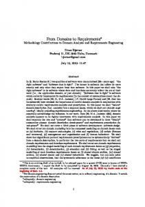
the CAD tool and don t take enough care if they respect the conditions of development. That s why we consider in our model that this step 3 is done in parallel to step 2. This part of the model consists in structuring in two BOMs: - The structure of the future product that has been identified by the designers through thinking on the potential final concept of it. This will be formalized through a product-BOM (p-BOM) - The CAD structure from the model of the product that follow directly from the CAD model, which will be formalized through a cad-BOM. We will not attach too much time to this step of the model, because these BOMs already exist in PDM softwares. So we will just use these BOMs and so these PDM tools to enrich our model. However, it s very important to be able to make a link between this two BOMs and the c-BOM stocked in TDC System because the aim is to link the requirements (base of the product development) to the CAD model which must only be a representation of the final product. For the moment this link to make communicate PDM tools and TDC System is not obvious. At the first though, we want to say that it must be done manually by the designer, but there is maybe another way to do it, which could be more automatic? 3.4 Step 4: Feeding of modelisation and simulation tools of different domain through a solver We have now all the informations needed to guarantee a product development taking into account all the requirements established at the beginning of the approach. The last step is now to make sure that these informations will be used on the right time and in the appropriate analysis tool from the concerned domain. This mission will be in charge of the solver that will be fed by TDC System, the PDM and eventually by the TDC Suite. TDC System will exchange the elements of the r-BOM, the fBOM and the c-BOM (that means requirements, functions and components) - as well as the elements that link these BOMs - with the solver. The PDM will exchange the informations about the product structure (p-BOM) and the cad-BOM that will help to generate the CAD model with the solver. It can be conceivable too that for some small information transfer (for example component characterization which is not include in the TDC System tool on our model for the moment), making a direct link between the TDC Suite and the solver can be pertinent. We need to explore this possibility in order to determine if it is judicious to make this direct link. In our research we don t focus on the solver, which is the subject of other researchers working on the CoDeKF project [19] (Collaborative Design and Knowledge Factory), a French research project lead by the University of Technology from Belfort and Montbéliard (UTBM) and supported by the TDC Software Company. Our research is involved in this project too. The idea of this solver emanate from the work of Gomes [20]. 4 APPLICATION TO AN EXAMPLE To illustrate this model, we will apply it to an example. For this first application, we have chosen a system which is not too complex: the quick system of a race car (the system that allows the driver to take on and off rapidly the wheel). We will develop this example through the four steps identified before. 4.1 Step 1: Functional Analysis To realize the Functional Analysis of the system, we have used the TDC Suite software. First, to realize the External Functional Analysis, we have used the module TDC Need of the software. The methodology helps us to define the service functions of the system thanks to the environment diagram (see Figure 5). On this diagram, we identify the interactors: Pilot, Steering wheel, Steering column and Command pallet of the gear box. We can identify the service functions too: - F1: Allow the pilot to take on and take off the steering wheel quickly (in blue) - F1.1: Be adaptable on every type of steering wheel (in orange) - F1.2: Be adaptable to the steering column (in pink) - F1.3: Be able to be connected to the junction box of the command pallet of the gear box (in burgundy) - F2: Protect the pilot against wound (in brown)
7
Pilot
Command pallet of the gear box F2 F 1.3 F1 Quick System
Steering w heel
F 1.2
F 1.1
Steering column
Figure 5: environment diagram of the system
The External Functional Analysis allows us to define the requirements too, thanks to the characterization of these functions notably. In fact, each service function is characterized with criteria, levels and flexibility. For example, the characterization of the service function F1 include the criteria Time to take off the steering wheel , which has the level maxi 2s and the flexibility F0 . Other requirements can be identified in the External Functional Analysis in others tools as the characterization table like for example in the general constraint. Second, we realize the Internal Functional Analysis (IFA). This one gives us the component list of the system. This list is composed by the components which have a functional meaning. That means, these components are not necessary the same as the components from the CAD model. In our example, we list the following components: System with clip in the steering column, Fixed part, Boring for fastening on the steering wheel, Inside grooves coincident with grooves of the steering column, Mobile part, Balls, Spring, Press stop on the balls, Cables connector between the pallet and the quick system. Moreover, the IFA gives us the link between these components and the service functions too, thanks to the Functional Block Diagram (FBD) tool. For example, we can see that the service function F1 is realized by the component System with clip in the steering column and Press stop on the balls (see Figure 6).
Figure 6: Functional Bloc Diagram of the quick system
This Functional Bloc Diagram shows the technical functions too. These functions can be identified in the contact between two components, in the closed flow, or in the interface functions which are the cutting of the service functions. With all these information organized in different tools, we obtain the FPS of the system, which give the conditions to be respected by the designers when they develop the product. These informations are very important for the designers and not always respected, because they are not always informed of it. At this point of our research, all the functions identified and developed here are general that means they concern the full system. In order to be sure to take into account the multi-domain characteristic of
8
the product, it can be interesting to give a type on each function. So the functions of the system could be Mechanic , Electronic or Mecatronic if it concerns both domains. If we apply that solution of sorting, we will have one more dimension in our model because there will be a mechanical f-BOM, an electronic f-BOM and maybe a mecatronic f-BOM and the same scheme will be observed for the cBOM. We have then the possibility too, to classify the functions in utilization functions, estheticism functions, etc. That can help the designer to know which functions are fundamental for the product and which are secondary. 4.2 Step 2: Migration from FA data into a BOM structure Now it is relatively easy to translate these precedent informations underlined by the Functional Analysis in BOM structure. We will obtain three different BOMs: the requirements-BOM (r-BOM), the functional-BOM (f-BOM) and the conceptual-BOM (c-BOM). For our example, the first one, the r-BOM, will be mainly obtained thanks to the characterization table. The r-BOM of the quick system will only have one level (see Figure 7).
Figure 7: r-BOM, f-BOM and c-BOM of the quick system
The second BOM, the f-BOM will be obtained in mixing the information contained in the octopus diagram, the functional tree and the FBD. This BOM can have many levels. For our example, we have 3 levels (see Figure 7). The third BOM, the c-BOM, is directly obtained by the component tree or the structure of the FBD. We can have many levels on this BOM too like in our example (see Figure 7). Finally, this migration from the Functional Analysis to the BOM structure can be enriched by making linking between the three BOMs. The first link is to be done between the r-BOM and the f-BOM, and can be done thanks to the correspondence between the functional tree and the service functions characterization that can be identified through the function characterization table (see Figure 8).
Figure 8: Link between r-BOM, f-BOM and c-BOM
9
Another link which can be done is between the f-BOM and the c-BOM. This link can be directly deduced from the Functional Bloc Diagram, because we can see on this diagram which component helps to realize which function. It could be interesting here to interpret the service functions in energetic flow as proposed in CoDeMo [21] and to work with a bond graph structure [22] like in the work of Klein Meyer [23], in order to obtain the functional surface of our product depending on the requirements identify at the beginning of the development. 4.3 Step 3: Design structure and modelisation of the concept The third step consisted in migrate the element of the CAD model into a cad-BOM for example, and to realize the p-BOM which is directly obtained from the work of the designers on the structure of the product. This step is done at the same time as the Functional Analysis today. Because the CAD is not our subject here, we will just consider that the p-BOM and the cad-BOM of the quick system are the following (see Figure 9).
Figure 9: p-BOM and cad-BOM of the quick system
Because these BOMs are not similar to the c-BOMs, even if they are constituted with components of the system, the link between them and the c-BOM from the step 2 must be done manually. That s what we have done here on our example; you can see the result of the manually link between the c-BOM and the cad-BOM on Figure 10.
Figure 10: link between c-BOM and cad-BOM, done manually
If we follow our meaning from the end of section 4.2, it can be pertinent to use here the functional surface identified before in order to create automatically an id corresponding to it in the CAD model. For example, for the « Boring for fastening on the steering wheel » component of the c-BOM, we can create in the CAD model an id with the same name. The designer can then create two, three, four or more entity of boring for this id if he wants, this element of the cad-BOM will always be linked to his counterpart in the c-BOM. This is an interesting research axis that merit to be developed.
10
4.4 Step 4: Feeding of modelisation and simulation tools of different domain through a solver We have now all the elements needed to develop our product in optimal conditions. Today, this fourth step is still not running. As explained in section 3.4, a part of this step the solver - is co-developed with others researchers of the team ERCOS from the SeT laboratory of the UTBM. The research on this subject is just beginning since some month. At full-term of this research, we will be able to integer our three BOMs deducted from the Functional Analysis in the solver, and we want that this one could distribute these data to the different analysis tools of the different systems.
4 CONCLUSION AND FUTURE WORK In this paper we have proposed a meta-model which describes the problem of communication between the different service and expert during the development of a multi-domain product. In analyzing the interactions of this meta-model, we have fixed two hypotheses: - We have decided not to center our research on the direct communication between the experts of two different domains. - We also don t develop the communication between different methods in our work. That means that we will essentially work on two types of communication between the both domains: the communication between models and the communication between analysis tools. Furthermore, we have fixed a third hypothesis for the rest of our work: we consider that the Functional Analysis method is common to the both domains and so applicable to the mechanical and the electronic part of the product. We have then deduced a model from this meta-model, which detailed the two links retained before. This model is made up by four steps: - Application of the Functional Analysis on the product developed, thanks to methodological software (like for example the TDC Suite). - Migration of the important data from the Functional Analysis (and so the TDC Suite software) to a data base organized in BOMs (Bill Of Material) in the TDC System software. - Achievement of the cad-BOM and the p-BOM in parallel work, stock in the PDM software. - Feeding of the solver with these homogeneous specifications. This one will then distribute the important information to the right modelisation and simulation tool of the right domain. These four steps will communicate together and exchange data. Finally, we have applied this model to an example, in order to show that through this model we can link all the main data of a product development (like requirements, functions, etc.), which are common to the two domain studied here (mechanical and electronic), to the modelisation and simulation tools of both domains. This concrete application has proved too, that if the designer modified something in the modelisation for example, he could be automatically informed that he will break the initial conditions defined in the Functional Performance Specifications. Through the analysis from the model and the application from an example on it, we have observed some possible further research axis. These axis, guide by other research works too, are the following: - In the step 1 of the model: we must think about the way to type the functions with their domain and maybe with their utilization. - In step 2 of the model: we must make the necessary development on the TDC System software, in order to make it able to support the three BOMs (r-BOM, f-BOM and c-BOM). - In the link between the step 2 and the step 3: we need to think about the right way to automate a part of the link, in using energetic flows to represent the service functions as proposed in CoDeMo [21] with a bond graph structure like in the work of Klein Meyer [23]. This could give us functional surface of our product which could be automatically generated in form of id in the CAD model. To conclude, the theoretical aspects have been explained in this paper. This work was very useful, especially to identify the following research axes that we must detail now and so allows us to propose
11
solutions to make both domain communicate correctly together. During the development of these research subjects, it will be important to think about the update of the different information involved in the meta-model when a decision or a requirement change. How can we guarantee the coherence of all these information? REFERENCES [1] French M.J. Engineering design: the conceptual stage. Heinemann Educational Books Ltd, London, 1971. [2] Pahl G. and Beitz W. Engineering Design: A Systematic Approach. The Design Council, London, 1984; original German text, Springer-Verlag, 1977. [3] Suh N. Principles of Design. Oxford University Press, New-York, 1990. [4] Albano L.D., Suh N.P. Axiomatic Approach to Structural Design. Research in Engineering Design, 4, 171-183, 1992. [5] Otto K. and Wood K., Product design. Prentice Hall, New-Jersey, 2001. [6] Ulrich K., Eppinger S.D. Product design and development. McGraw-Hill, New York, 1995. [7] Monticolo D., Frey E. and Gomes S. An approach to acquire and reuse multi-domain knowledge at the time of mechanical design project. In IDMME 2008. [8] Frey E., Gomes S. and Sagot J.C. Vers des informations méthodologiques interfacées aux outils de modélisation et de simulation pour une meilleure performance du processus de conception multi-métiers. In CONFERE 2008. [9] Gero, J S. Design prototypes: a knowledge representation schema for design. AI Magazine Vol 11 No 4 (1990) 26 36. [10]Lemesle R. Transformation Rules Based on Meta-Modeling. IEEE EDOC'98, La Jolla, California, 1998, p. 113-122. [11]Madhavan P.A., Bernstein P. and Halevy A. Representing and reasoning about mappings between domain models. In Proc. 18th National Conference on Artificial Intelligence (AAAI 02), Edmonton, Alberta, Canada, 2002. [12] Park J. and Ram S. Information System Interoperability: What Lies Beneath? ACM Transactions on Information Systems, Vol. 22(4), 2004. [13] Dupinet E. Contribution à l'étude d'un système informatique d'aide à la conception de produits mécaniques par la prise en compte des relations fonctionnelles. Thesis from the Ecole Centrale Paris, France, September 1991. [14] Noël F., Roucoules L. and Teissandier D. Specification of product modeling concepts dedicated to information sharing in a collaborative design context. In international conference on Integrated Design and Manufacturing in Mechanical Engineering IDMME 2004. [15] Song H., Roucoules L., Eynard B. and Lafon P. Interoperability between Cooperative Design Modeller and a CAD System: Software Integration versus Data Exchange. In the International Journal for Manufacturing Science and Production IJMSP 2006. [16] Tichkiewitch S. Specification on integrated design methodology using a multi-view product model. In Engineerign System Design and Analysis Conference ASME 1996. [17] http://www.tdc.fr. Website of the TDC Software company. [18]French and European norm NF EN1325-2. Vocabulaire du management de la valeur, de l analyse et de la valeur et de l analyse fonctionnelle. AFNOR, March 2005. [19] http://codekf.org/. Website of the CoDeKF project. [20] Gomes S. Ingénierie à base de connaissances pour une conception, productive, optimisée, collaborative et innovante du système Projet-Produit-Process-Usage. Habilité à diriger les recherches, 13. Oktober 2008. [21] Roucoules L. and Tichkiewitch S. CODEMO: A cooperative design environment - a new generation of CAD systems, Concurrent engineering: research and applications, 2000, 8/4, 263-280. [22] Thoma J. Introduction to Bondgraphs and their Application. Perga-mon Press, Oxford, 1975 [23] Klein Meyer J.S., Roucoules L., De Grave A. and Chaput J. Case study of a MEMS switch supported by a FBS and DFM framework. In proceedings of the 17th CIRP Design Conference, Berlin, 2007. ISBN 978-3-540-69819-7.
12