Annals of Software Engineering 10 (2000) 151–176
151
From conceptual modelling to requirements engineering Colette Rolland a and Naveen Prakash b a
Universit´e Paris 1-Sorbonne, 17, rue de la Sorbonne, 75231 Paris Cedex 5, France E-mail:
[email protected] b Delhi Institute of Technology, Pappankala, 110045 Delhi, India E-mail:
[email protected]
Conceptual modelling is situated in the broader view of information systems requirements engineering. Requirements Engineering (RE) explores the objectives of different stakeholders and the activities carried out by them to meet these objectives in order to derive purposeful system requirements and therefore lead to better quality systems, i.e., systems that meet the requirements of their users. Thus RE product models use concepts for modelling these instead of concepts like data, process, events, etc., used in conceptual models. Since the former are more stable than the latter, requirements engineering manages change better. The paper gives the rationale for extending traditional conceptual models and introduces some RE product models. Furthermore, in contrast to conceptual modelling, requirements engineering lays great stress on the engineering process employed. The paper introduces some RE process models and considers their effect on tool support.
1.
Introduction
A number of studies show [Lubars et al. 1993; McGraw and Harbison 1997; The Standish Group 1995] that systems fail due to an inadequate or insufficient understanding of the requirements they seek to address. Further, the amount of effort needed to fix these systems has been found to be very high [Johnson 1995]. To correct this situation, it is necessary to address the issue of requirements elicitation, validation, and representation in a relatively more focussed manner. The expectation is that as a result of this, more acceptable systems will be developed in the future. The field of requirements engineering has emerged to meet this expectation. The traditional way of engineering information systems is through conceptual modelling which produces a specification of the system to be developed. This specification concentrates on what the system should do, that is, on its functionality. Such a specification acts as a prescription for system construction. Of the assumptions on which conceptual modelling is based, we find three very important ones: • System requirements are highly stable, i.e., they do not change with time. As a consequence, the conceptualised system is itself stable. J.C. Baltzer AG, Science Publishers
152
C. Rolland, N. Prakash / From conceptual modelling to RE
• System requirements are given. Users have just to be questioned about their requirements. Thus, the interesting problem is that of specifying the system to meet these requirements. System analysts are the right persons to do it. • Validation of system requirements can be done with reference to system functionality. In other words, the conceptual schema is the appropriate support for communicating, negotiating and reaching an agreement with users and system stakeholders. Today, it is becoming clear that these assumptions do not hold any longer. Due to economic pressure and emergence of new technologies, organisations change much faster than before. As a consequence, expectations from information systems also change much faster which, in turn, implies that requirements are no longer stable [Harker et al. 1993]. Understanding and recording the effect of business changes on requirements is considered by Lubars et al. [1993] as an issue which has not been solved yet. It is also known that requirements change even as the system is being developed. This causes considerable problems during development as reported by Curtis et al. [1988]. Since requirements change, it is no longer possible to treat them as given. Rather, it is necessary to determine new requirements for legacy systems and to carry requirements models through the entire systems life cycle. Further, the central role of system analysts is taken over by a consortium of stakeholders who bring their specific view points on what the system should do [Finkelstein et al. 1990]. Finally, requirements validation must now be rooted in organisational change rather than in system functionality: if requirements models are to be validated then, this validation must be with reference to organisational needs rather than system functionality. It is only then that computer based systems will be able to adapt to changing organisational needs. In tackling these problems, the area of requirements engineering tries to go beyond the functionality based view of conceptual modelling. We highlight here two dimensions along which this attempt is made: • Requirements engineering extends the “what is done by the system” approach with the “why is the system like this” view. This why question is answered in terms of organisational objectives and their impact on information systems supporting the organisation. In other words, information systems are seen as fulfilling a certain purpose in an organisation and requirements engineering helps in the conceptualisation of these purposeful systems. This has two implications (a) elicitation and validation of the requirements of a system is done with respect to their purpose in organisations and (b) only organisationally purposeful systems are conceptualised. • Requirements engineering does not deal with the functionality of a system. Rather, it assumes that the potential users of the system provide useful and realistic view points about the system to be developed. Therefore, a detailed exploration of the various ways in which the system might be used and the activities it shall carry out is performed. This can be done, for example, by looking at typical interactions that are expected to occur with the system. This exploration leads to the identification of ‘normal’ and ‘exceptional’ activities whose integration models the full system
C. Rolland, N. Prakash / From conceptual modelling to RE
153
behaviour. In this sense, the determination of what the system must do is an interesting question in requirements engineering. To deliver the foregoing, an appropriate way of doing requirements engineering must be found and supported by computer based environments. First, changing requirements imply that the assumptions made, the decisions taken, and the alternatives explored must all be recorded and be made available for future use. Second, since requirements engineering is a complex task, advice/guidance on which activities are appropriate in given situations as well as on how these activities are to be performed must be provided. Finally, considerable freedom in deciding which activity is to be done next must be made available to the requirements engineer. The foregoing indicates that there are three interesting aspects of requirements engineering, namely, conceptualisation of purposeful systems, modelling of system usage, and the process support needed for doing requirements engineering. We will highlight these in the rest of this paper. The attempt will be to show that these three aspects represent a basic departure from conceptual modelling. In the next section we review the area of conceptual modelling. Thereafter, we turn our attention to requirements engineering and consider separately the three issues of conceptualising purposeful systems, modelling system usage and the process support. 2.
Conceptual modelling
Traditionally, information system engineering has made the assumption that an information system captures some excerpt of world history and hence has concentrated on modelling information about the Universe of Discourse [Olle et al. 1988]. Thus conceptual modelling can be treated as the first phase of the two-phase organisation of the information system life-cycle shown in figure 1. It aims at abstracting the specification of the required information system, i.e., the conceptual schema, from an
Figure 1. Two-phase organisation of system life-cycle.
154
C. Rolland, N. Prakash / From conceptual modelling to RE
analysis of the relevant aspects of the Universe of Discourse about which the user community needs information [Dubois et al. 1989]. The succeeding phase, that of system engineering, uses the conceptual schema to design and implement a working system which is verified against the conceptual schema. 2.1. Classification framework of conceptual models The information systems community has developed a large number of conceptual models for representing conceptual schemata. This variety has arisen because of the need to capture as many aspects of real world semantics as possible. Given this plethora of models, it has been found necessary to develop frameworks for classifying and understanding these. One framework which classifies models based on the perspective adopted to view the Universe of Discourse was developed by [Olle et al. 1988]. It organises models into the classes of process-oriented, data-oriented, and behaviouroriented models. In figure 2, this framework has been shown as defining a threedimensional space within which conceptual models can be positioned. The three dimensional framework highlights the fact that information systems can be looked upon in three different ways. When seen as process-oriented, an information system is a function in an organisation which returns some information. When seen as data-oriented, information systems are viewed as mirroring the information contents of organisations and it is expected that the information system would be a supplier of this information. Finally, in the behavioural perspective, an information system is an artefact which handles interesting events that occur in the organisation by performing one or more functions. These functions modify the information contents of the information system which are again available for manipulation through events. These different views naturally lend themselves to specific kinds of treatment. Thus, when the information system is viewed as a function in the Universe of Discourse, then during analysis, the components of this function are discovered. This is because the function may be very complex and needs to be broken down into its functional elements to understand it better. If any of the functional components are
Figure 2. The three dimensional framework for classifying conceptual models.
C. Rolland, N. Prakash / From conceptual modelling to RE
155
themselves complex then, they are decomposed recursively till simple, well understood functions are reached. Clearly, this results in a hierarchy of functions rooted in the original function. Whereas this hierarchy identifies the functional components of the information system function, it does not establish an inter-relationship between these components, i.e., which function receives data from which function and sends data to which one is not articulated. This is done by using conceptual models for building data flow diagrams. It can be seen that the process-oriented perspective views information systems as processors of information. In contrast, the data oriented approach looks at an information system as mirroring the information contents of the real world, as a storehouse of information. Since information is to be kept about real life things, an identification of all these relevant ‘things’ coupled with their abstraction as information carrying entities is carried out. The abstracted entities and their inter-relationships are then represented as a conceptual schema. As the mirrored world changes, so the information system must reflect these changes. Therefore the information system is seen as a data manager, maintaining and delivering information at all times. Finally, in the behavioural perspective, the attempt is to identify the interesting events that occur in the real world, the information affected by their occurrence and the functions that cause this effect to be felt. For this, three things are done (a) real events are abstracted into information bearing events, (b) real world things are abstracted (as in the data perspective) into information bearing entities and relationships, and (c) functions to be invoked to carry out the effect of the event are identified and associated with it. It can be seen that the behavioural view promotes a transaction management view of an information system. Over the years, the usefulness of having three completely different perspectives with little integration in them has come to be questioned. Two distinct trends towards integration emerged. The first was the development of object-oriented conceptual models, the majority of which integrated together the process and data-oriented perspectives, though some conceptual models that also integrated the behavioural one were developed [Brunet et al. 1990; Desfray 1994; Martin and Odell 1992]. The second was a trend towards ‘loosely connected’ conceptual models which consisted of a set of conceptual models, each according to a different perspective. Therefore, the Universe of Discourse was conceptualised as individual but connected conceptual schemata. This inter-connection was seen in the Yourdon approach [Yourdon 1989] in the mid-eighties which loosely connected the data flow, ER modelling and state transition diagram techniques. It was also seen later in OMT [Rumbaugh et al. 1991] which integrated an object-oriented model with data flow diagrams and event modelling. 2.2. Conceptual modelling process The conceptual modelling community emphasised the product aspects of systems at the expense of the process employed to deliver the product. Thus, the structure of the conceptual schema, its completeness, and consistency etc. was more important
156
C. Rolland, N. Prakash / From conceptual modelling to RE
than how it was developed. Early process models were activity based. They looked upon the process as consisting of a set of activities which could be decomposed into simpler ones and which were linearly ordered. Every successive activity was to be performed after the completion of the previous one. Such process models are known to be restrictive [Wynekoop et al. 1993] because they assume: (a) That it is possible to pre-define the development path that can be taken through the activities of a process model. Thus, they restrict the creativity of the developer in choosing a path specific to a given situation. (b) That each conceptual schema is built afresh and therefore there is no need to keep track of the processes that built them. (c) The ‘upon completion’ rule which prohibits movement to an activity later in the order or backtracking to one earlier in the order. (d) That the relationship between an activity and the product built by it was not interesting. Later, a number of other more flexible process models were built. Yet, by and large, conceptual modelling continued to follow the activity based approach to process models, i.e., the Waterfall model [Royce 1970]. 3.
Requirements engineering models
In the view of requirements engineering being proposed here, we consider that requirements come from two sources, users and the domain environment. The first source provides informal statements of goals and users’ intentions expressed in natural language. The second source provides requirements reflecting real world facts and constraints on the designed system implied by laws of physics independently of any user’s need or wish. Hence requirements may be divided into two sub-types: (1) user-defined requirements which arise from people in the organisation and reflect their goals, intentions and wishes, (2) domain-imposed requirements which are facts of nature and reflect domain laws. This implies that the Universe of Discourse has to be partitioned into two, the usage world and the subject world [Jarke and Pohl 1993]. The usage world describes the tasks, procedures, interactions etc. performed by agents and how systems are used to do work. It can be looked upon as containing the objectives that are to be met in the organisation and which are achieved by the activities carried out by agents. Therefore it describes the activity of agents and how this activity leads to useful work. The second part of the Universe of Discourse, the subject world, contains knowledge of the real world domain about which the proposed system has to provide information. It contains real world objects which are to be represented in the conceptual schema.
C. Rolland, N. Prakash / From conceptual modelling to RE
157
Figure 3. The relationships between the usage, system and subject worlds.
There is a third world, the system world which is the world of system specifications in which the requirements arising from the two worlds must be addressed. The system world holds the modelled entities, processes, and events of the subject and usage worlds as well as the mapping from these conceptual specifications to the design and implementation levels of the software system. All these worlds are interrelated as shown in figure 3. User-defined requirements (sub-type 1 above) are captured by the intentional relationship and the usage fit relationship. Domain-imposed requirements (sub-type 2 above) are captured by the domain genericity relationship. Finally, it will be noticed that there is a representation relationship between the subject world and the system world which relates the domain to its representation in the system. This relationship has been the only focus of conceptual modelling whereas requirements engineering highlights the importance of the three other relationships, namely the intentional, usage fit and domain genericity relationships. All three relationships address the ‘why’ question and therefore provide the rationale for system development. 3.1. Relationships between the usage world and the system world The usage world consists of individuals, social groups and organisational settings in which the system is intended to function. The individual, pragmatic relationship with the system world is provided by the usage fit relationship of figure 3 whereas the social, semiotic relationship is provided by the intentional relationship. The usage world provides the rationale for building a system. The purpose of developing an information system is to be found outside the system itself, in the enterprise, or in other words, in the context in which the system will function. The social relationship between the usage and system world addresses the issue of the system purpose and relates the system to the goals and objectives of the organisation. This relationship explains why the system is developed. Modelling this establishes
158
C. Rolland, N. Prakash / From conceptual modelling to RE
the conceptual link between the envisaged system and its changing environment. This suggests an augmentation of conceptual modelling to deal with the description of the context in which the system will function. In the area of requirements engineering, goal-driven approaches have been developed which directly model organisational objectives and relate them to system functions. These approaches address the semiotic, social link between the usage and the system world. As brought above, the usage world is the world of the system users who will individually work with the system to meet the objectives assigned to them by the organisation. Additionally, each of them has his/her own view point and requirements regarding the system to be constructed. Taking these into account helps in the construction of relatively more acceptable systems. This suggests another augmentation of conceptual modelling, to include the role of individuals thereby enabling the derivation of system functionality from the integration of users’ view points. In requirements engineering, the areas of scenario modelling and use case development take this into account. Goal driven approaches model organisational objectives so as to relate them to the functions of the system. In this sense, they aim at the conceptualisation of purposeful systems only. They contribute to the interpretation of requirements before they are understood and before they are transformed into system function specifications. Thus they support conceptualising purposeful systems. Scenario based approaches, by focussing on the users’ view points, help in modelling purposeful system usage from which useful system functions can be derived. Scenarios provide dynamic meaning to goals whereas goals provide the intentional setting within which scenarios find meaning. 3.1.1. Goal driven approaches The broader view of a requirements specification that we advocate here is one that goes beyond the classical conceptual schema describing system functionality. It includes enterprise modelling which represents the why part of system requirements. This part complements the what part provided by conceptual modelling. Enterprise modelling has been developed for example, in the F3 project [Bubenko and Kirikova 1994; Bubenko et al. 1994] to provide a set of models for understanding the requirements and bridging the gap between ill-defined problems and application situations as well as to define requirements of information systems formally and precisely. The requirements specification is represented as a structured description of five interrelated sub-models (see figure 4) which provide the context within which requirements are elicited. Each sub-model represents a particular concern or view in requirements acquisition, and these sub-models help in separating the different concerns. The sub-models are not developed in a linear, sequential manner. Although the process usually starts with an objectives model and progresses through actor and activity models to information systems requirements this is not always the case. For instance, given a legacy system the activity and concept models may be developed first by reverse engineering previous designs.
C. Rolland, N. Prakash / From conceptual modelling to RE
159
Figure 4. The sub-models of the F3 approach.
The objectives sub-model describes the why component of a requirements specification. It is a graph with goals, problems, opportunities and weaknesses as nodes connected through relationships of the type ‘motivates’. The concept sub-model is used to define the Universe of Discourse that concerns requirements engineers. It may serve as a dictionary of user and customer defined concepts. The actors sub-model is used to define the actors in the domain and their relationships with activities and objectives. Actors may be individuals, groups, roles, organisational units, systems, etc. Actors are related to goals in the objectives submodel and therefore represent stakeholders who are responsible for achieving goals through activities described in the activities sub-model. The activities sub-model describes the processes and tasks of the enterprise. Components in this sub-model are created to achieve goals in the objectives sub-model, referring to components of the concepts sub-model, and resources required to carry out these activities described in the actors sub-model. The information system requirements sub-model is meant to be derived from the other models. It includes both functional and non functional requirements. The former typically indicate needs for establishing objects, defining operations and services (in Object-Oriented terms) or functions (in top-down decomposition such as Structured Systems Analysis). The latter are related to the environment, performance and quality of the required system. Enterprise modelling offers a set of interrelated models, each constructed with a set of predefined components types and relationships to address the ‘why’ question and understand where the ‘what’ requirements come from. The semantic links from the set of interrelated sub-models and the information system requirements model are established for reflecting the rationale, the motivation, for designing a specific information system. Enterprise modelling was further refined in the EKD method to support change management [Kardasis and Loucopoulos 1998; Loucopoulos et al. 1998; Rolland et al.
160
C. Rolland, N. Prakash / From conceptual modelling to RE
1997, 1998b]. In the KAOS approach [Dardenne et al. 1991, 1993], the emphasis is on supporting formal refinement of high level goals into system constraints. Although generic models are advocated, goal modelling and refinement have supplied simple guidance via heuristics [van Lamsweerde et al. 1995]. The I* approach [Yu and Mylopoulos 1994a, b, c] creates models of the environment of the system that emphasise agents and their relationships. Their strategic dependency and rationale models allow tracing of dependencies between agents, goals and tasks and support reasoning to identify trade-offs between functional requirements and non functional requirements [Mylopoulos et al. 1992]. Although goal modelling has proved to be useful for specifying purposeful systems, practical experience shows that there are still a number of difficulties. First, it is often assumed that systems are constructed with some goals in mind. However, in reality goals are not given and therefore the question as to where they originate from acquires importance. In addition, enterprise goals which initiate the goal discovery process do not reflect the actual situation but an idealised one. Therefore, proceeding from this may lead to ineffective requirements. Eliminating uninteresting and spurious goals is difficult [Potts 1997]. Additionally, the application of goal reduction methods [Dardenne et al. 1993] to discover the components goals of a goal, is not as straightforward as literature suggests. Finally it seems to be difficult to deal with the fuzzy concept of a goal. This led to some formalisation of the notion of a goal [Prat 1997; Rolland and Ben Achour 1997]. Yet, domain experts need to discover the goals of real systems. 3.1.2. Scenario based approaches Independently of goal modelling, an alternative approach to RE, the scenariobased approach [Jacobson 1995], has been developed. By capturing examples, scenes, narrative descriptions of contexts, use cases and illustrations of agent behaviours, scenarios have proved useful in requirements elicitation in a number of ways: to elicit requirements in envisioned situations [Jarke and Pohl 1993], to help in the discovery of exceptional cases, to derive conceptual object-oriented models, to understand needs through scenario prototyping and animation, to reason about design decisions, to create context for design [Rolland and Prakash 1994] and so on. The underlying reason for the popularity of scenario-based approaches seems to be that people react to descriptions of real happenings and real things. This reaction helps in clarifying requirements expected of systems. Thus, the scenario school argues, that typical scenarios are easier to get in the first place than goals. Goals can be made explicit only after deeper understanding of the system has been gained. Scenarios have been developed [Rolland et al. 1998c] for different purposes with different contents, expressed in different levels of abstraction and with different notations. In so far as their purpose is concerned, scenarios can be descriptive, explanatory or exploratory. Descriptive scenarios capture requirements by enabling the analyst and users to walk through a process and understand its operations, actors, the events
C. Rolland, N. Prakash / From conceptual modelling to RE
161
triggering the process etc. Thus, descriptive scenarios aid in the clarification of how a process performs, who are the involved parties and how the process is activated as well as the conditions under which it is activated. Explanatory scenarios raise issues and provide rationale for these issues. They identify why something happens in the real world, what leads to it, what are its causes, what are commonly occurring events which require handling etc. Through this the attempt of explanatory scenarios is to describe the desirable features of the system to be developed. Finally, exploratory scenarios are useful when different possible solutions exist for satisfying given system requirements. These solutions are to be examined and evaluated to arrive at the right solution. Such scenarios establish a direct link between requirements and desired solutions. As mentioned above, scenarios have different contents. This can be behavioural information identifying the actions, activities, events carried out in the usage world; a description of the objects of the subject world together with their attributes; events and event histories; organisational information like the structure of the company, the groups, departments and agents found in it etc.; stakeholder information including the characteristics of people, their views and aspirations [Nardi 1992]. However, by and large scenarios concentrate on the functional features required of a system. Finally, scenarios have been expressed at three different levels of abstraction, instance, type and mixed. In the former case, a scenario uses specific names or events with real argument values. These scenarios describe particular instances of use which can form the basis for discussion of what happens, why and how. Type scenarios do not use individual entities but entity types. Thus they do not refer to Smith but to customers. Each execution of a type scenario is an instance scenario. Finally, mixed scenarios are those that have some parts at the instance level and others at the type level. Scenarios have been expressed in different notations ranging from the informal, semi-formal to the formal. Informal scenarios use natural language, videos, story descriptions etc. and are valuable in those cases where the user community is unwilling/unable to deal with formal notation. Semi-formal scenarios use a structured notation like tables and scenario scripts in capturing real activities. Finally, formal scenarios are expressed in modelling languages based on regular grammars or statecharts. They are useful to run as simulations to present a vision of what the future system will look like and to gauge user reactions to it. 3.1.3. Coupling goals and scenarios In order to overcome some of the deficiencies and limitations of goal-driven and scenario-based approaches used in isolation, some proposals have been made recently to couple goals and scenarios together. Goals have been considered as contextual properties of use cases and as a means to structure use cases. The goal scenario combination has been used to operationalise goals, to check whether or not the current system usage captured through multimedia scenarios fulfils its expected goals, to infer goals specifications from operational scenarios and to discover new goals through scenario analysis.
162
C. Rolland, N. Prakash / From conceptual modelling to RE
As an example of an approach which combines goal modelling and scenario authoring consider the CREWS-L’Ecritoire approach [Rolland and Ben Achour 1997; Rolland et al. 1998a] developed within the CREWS ESPRIT project. CREWSL’Ecritoire uses a bi-directional coupling allowing movement from goals to scenarios and vice versa. The complete solution is in two parts: when a goal is discovered, a scenario can be authored for it and once a scenario has been authored, it is analysed to yield goals. By exploiting the goal-scenario relationship in the reverse direction, i.e., from scenario to goals, the approach proactively guides the requirements elicitation process. In this process, goal discovery and scenario authoring are complementary steps and goals are incrementally discovered by repeating the goal-discovery, scenario-authoring cycle. In order to give some insights into the approach, we first present some of the key concepts and terminology of the CREWS-l’Ecritoire approach and then provide a brief overview of its process. (a) Concepts and terminology • A Requirement Chunk (RC) is a pair hG, Sci where G is a goal and Sc is a scenario. Since a goal is intentional and a scenario is operational in nature, a requirement chunk is a possible way of achieving the goal. • A goal is defined as “something that some stakeholder hopes to achieve in the future” [Plihon et al. 1998]. It is expressed [Prat 1997] as a clause with a main verb and several parameters, where each parameter plays a different role with respect to the verb. An example of a goal expressed in this structure is the following: Provide verb (efficiently) qual (electricity) tar (from PPC producer) so (to our noneligible customer) ben (using the PPC network) means (in a normal way) manner . • A scenario is “a possible behaviour limited to a set of purposeful interactions taking place among several agents.” It is composed of one or more actions, an action being an interaction from one agent to another. The combination of actions in a scenario describes a unique path. A scenario is characterised by initial and final states. An initial state attached to a scenario defines a precondition for the scenario to be triggered. A final state defines a state reached at the end of the scenario. We distinguish between normal and exceptional scenarios. The former leads to the achievement of its associated goal whereas the latter fails in goal achievement. • Requirement chunks classification and abstraction levels: Three levels of abstraction called contextual, functional, and physical are available.. The contextual level identifies the services that a system should provide to an organisation and their rationale. The functional level focuses on the interactions between the system and its users to achieve the needed services. Finally, the physical level deals with the actual performance of the interactions. Each level corresponds to a type of requirement chunk. • Relationships between requirement chunks: There are three types of relationships among requirement chunks, namely, the composition, alternative, and refinement relationships. The first two of these lead to a horizontal AND/OR structure be-
C. Rolland, N. Prakash / From conceptual modelling to RE
163
tween RCs. AND relationships among RCs link together those chunks that require each other to define a completely functioning system. RCs related through OR relationships represent alternative ways of fulfilling the same goal. The third type of relationship relates requirement chunks at different levels of abstraction. The refinement relationship establishes a vertical link between requirement chunks. (b) The requirements elicitation process The CREWS-L’Ecritoire process aims at discovering/eliciting requirements through a bi-directional coupling of goals and scenarios allowing movement from goals to scenarios and vice-versa. As each goal is discovered, a scenario is authored for it. In this sense the goal-scenario coupling is exploited in the forward direction from goals to scenarios. Once a scenario has been authored, it is analysed to yield goals. This leads to goal discovery by moving along the goal-scenario relationship in the reverse direction. The exact sequence of steps of the process is as follows: 1. Initial Goal Identification Repeat 2. Goal Analysis 3. Scenario Authoring 4. Goal Elicitation Through Scenario Analysis until all goals have been elicited. Each of the three steps of the cycle is supported by mechanisms to guide the execution of the step. The guidance mechanism for goal analysis is based on a linguistic analysis of goal statements. It helps in reformulating a narrative goal statement as a goal template (introduced in the previous section). The mechanism for scenario authoring combines style/content guidelines and linguistic devices. The former advise authors on how to write scenarios whereas the latter provide semi-automatic help to check, correct, conceptualise, and complete a scenario. Finally, the three different goal discovery strategies for goal elicitation introduced earlier are used. 3.2. The domain genericity relationship between the subject and system worlds Traditionally the focus in the representation relationship (see figure 3) has been on objects, events, operations, etc., i.e., on the functional aspects of the information system. Non-functional quality criteria such as confidentiality, performance, accuracy and timeliness of information can also be attached to this representation relationship. However. methodologies of today rarely take this into account. There is another modelling concern captured through the domain genericity relationship, the role and impact of domain knowledge [Jackson 1994]. Since many new applications have the same requirements as earlier ones, one possibility is to create generic domain models as templates for requirements of certain classes of ap-
164
C. Rolland, N. Prakash / From conceptual modelling to RE
Figure 5. Meta-schema for domain modelling.
plications. This facilitates reuse in requirements engineering by providing sets of predefined generic requirements for developing system requirements specification. Dependencies between systems and their domain environments have been analysed in detail by [Jackson 1994; Jackson and Zave 1993]. They formalise event dependencies between the system and its environment that are inherent to the laws of physics, e.g., obligations for the required system in avionics and other real-time applications. The separate consideration of the subject world allows the development of domain ontologies which consider typical classes of object and activity abstractions as reusable modelling patterns which can significantly reduce the requirements engineering effort. A model library for the subject world has been developed for example, in the NATURE project [Sutcliffe and Maiden 1994]. A model is a problem abstraction which defines in generic terms the structure and the behaviour of the problem space. It is a unit of abstraction that aggregates objects linked by a purpose. The concepts used to define object models are shown in figure 5. • Objects: have properties and states. • Structure objects: model containment of objects for example a library contains books. • State transitions: model behaviour of objects and enable goal state to be achieved. • Events: model initiating ‘triggers’ and time points. • Stative conditions: are tests on objects’ states. • Goal states: describe a required state that should be satisfied.
C. Rolland, N. Prakash / From conceptual modelling to RE
165
Figure 6. Hierarchy of object class models.
Semantic relationships: specify constraints between objects, state transitions and states. Object models are structured in a class hierarchy. Models at different levels of abstraction are distinguished using different types of knowledge. Object structure and purpose are the most important constructs at higher levels because they discriminate effectively between different problem classes. The top level in the hierarchy is defined by state transitions, agents, states and semantic relations. Lower level object models are specialised by adding further knowledge such as goal states, events, conditions and object properties. The highest levels of the object class hierarchy are illustrated in figure 6. The library is used in the NATURE toolset by the matcher to identify the models relevant for the application at hand. 4.
Requirements engineering process support
Since conceptual modelling largely ignored the development process, methods for conceptual modelling are a maze of steps, guidelines, checklists, heuristics etc. It was assumed that the process of development was linear, Cartesian in nature. Therefore, it was quite usual to base methods and tools on process models like the Waterfall model [Royce 1970]. In contrast, requirements engineering has explicitly considered the issue of the process support to be provided. Two important issues arise: 1. How can attention be channelled to deal with the real productive tasks of requirements engineering? In other words, it is necessary to guide the requirements engineering process to concentrate on discovering goals, scenarios, etc. 2. How can one learn from past practice? That is, if some decisions were taken in a given situation in the past then how can one benefit from experience with that? Thus it is necessary to keep a trace of past decisions.
166
C. Rolland, N. Prakash / From conceptual modelling to RE
These two aspects of the requirements engineering process, namely guidance and tracing must be actively supported by computer assisted tools. 4.1. Guidance Some experience in guidance exists in software engineering where guidance was classified as active or passive [Dowson and Fernstrom 1994]. The former was focussed on ensuring that the development process employed was an instance of the process model and consequently, guidance was directed towards process model enforcement. The latter was concerned with an identification of what could be done next in the development process. In [Feiler and Humphrey 1993], passive guidance has been defined as the generation and subsequent presentation of the set of legal steps that were available at any moment in the development process. One out of these could then be selected as the task to be done next. The software engineering view is that active guidance should be provided. Thus, guidance cannot be provided without an adequate process model. Existing process models do not seem adequate to requirements engineering as they prescribe a predefined plan of actions. Activity-oriented process models [Royce 1970] come from an analogy with problem-solving and provide a frame for manual management of projects. This linear view is inadequate for methods which support backtracking, reuse of previous designs, and parallel engineering. Productoriented process models [Finkelstein et al. 1990; Franckson and Peugeot 1991; Humphrey and Kellner 1989] represent the development process through the evolution of the product. They permit design tracing in terms of the transformations performed and the resulting products. Finally, decision-oriented models integrate more deeply the semantics attached to evolutionary aspects. The notion of design decision facilitates understanding of the designer’s intention, and better reuse of results [Potts 1989] but the flexibility and situatedness of requirements engineering processes is not adequately handled in existing decision-oriented models. The importance of situatedness in process modelling is also acknowledged by the software engineering community where it was found that departures from the process model occurred in actual practice. A concerted effort was put in to allow process models to respond to these departures. One approach was to assume prescriptive models and then, modify them to accommodate real processes. This modification could be achieved in two ways. First the extent of deviations from the prescription that could be allowed was modelled as constraints. Any actual deviation that satisfied the constraints was therefore manageable and the process enactment mechanism could handle it. This way of handling deviations took the prescriptive approach to its logical conclusion: it prescribed the deviations allowed in a prescription. The second way of handling deviations was to allow changes to be made in the prescription as and when they are needed. Thus, a level of dynamicity is superimposed on the basic prescription. In contrast to this, the requirements engineering community recognised that the core of their task was the generation and exploration of alternatives from which
C. Rolland, N. Prakash / From conceptual modelling to RE
167
the right one is selected for the situation at hand. This can be seen in the IBIS process model [Potts 1989] where a number of alternatives for resolving an issue were generated. This process model is at a very high level of abstraction and had to be buttoned down to real methods and tools. The contextual model [Pohl 1996; Rolland and Cauvet 1991, 1994, 1995] attempted to do this. A context was defined here as the application of an intention to a given requirements engineering situation. It organised requirements engineering methods as a set of contexts of three kinds, executable, plan, and choice contexts respectively. A Choice context groups together all possible alternative ways of meeting its intention. These alternatives were themselves contexts thus leading to a hierarchy of alternatives. A plan context is a collection of simpler contexts such that their execution, in the various possible orders prescribed in the plan context meets its intention. Finally, an executable context is one which can be directly executed to meet its intention (and is atomic in this sense). It can be seen that the contextual model attempted to reconcile process prescription with alternative generation, the former through plan contexts and the latter through choice contexts. Another attempt to root the notion of alternatives in methods was made in the decisional approach [Prakash 1997]. There were decisions of three types, atomic, complex and abstract related to each other by two different kinds of dependencies. The first of these identified which decisions can be performed after a given one whereas the second one identified those that must be performed after it, though not necessarily immediately. Recognising the crucial role played by the product situation, the interest was in generating the set of decisions that were applicable to a given product situation. Prescriptive capability was provided through the notion of complex decisions which could be built out of simpler decisions whose order of execution was prescribed. Finally, abstract decisions could be built as abstractions and provided high level abstract choices for application engineers. Experience with the contextual and decisional models showed that a key discriminant factor in real processes is the product situation. This situation has a strong bearing in selecting the task best suited to handle it and also the strategy to be adopted in carrying out this task. These strategies need to be reflected in the process model so that the right one can be dynamically chosen. A recent attempt to model the strategic dimension of the requirements engineering process through a set of strategies to select tasks adapted to situations was made in [Rolland et al. 1999] and [Ralyte et al. 1999]. The process model is represented as a labelled directed graph called a map. The map uses two fundamental notions, intention and strategy. An intention captures in it the notion of a task that the requirements engineer intends to perform whereas the strategy is the manner in which the intention can be achieved. The nodes of the map are intentions whereas its edges are labelled with strategies. The directed nature of the map identifies which intention can be done after a given one. The only way in which a process can be built is dynamically, through the use of guidelines for selection among alternatives. Only after the intention and the strategy have been decided is there a need for a guideline to achieve the intention. There are three guidelines associated with the map:
168
C. Rolland, N. Prakash / From conceptual modelling to RE
• intention selection guidelines for determining all succeeding intentions of a given one, • strategy selection guidelines for determining the strategies from which one is selected, • intention achievement guidelines for defining the way in which an intention can be achieved. Thereafter, the enactment mechanism is invoked to actually carry out the tasks. It can thus be seen that the requirements engineering community has made a conscious effort towards developing guidance to meet its two most basic needs: (a) generating the set of alternatives applicable to a given product situation, and (b) reducing the amount of prescription to only those parts of the process where it is essential. 4.2. Tracing In the requirements engineering community there is no longer the question whether traceability is a useful thing or not. Capturing and maintaining traces is seen as an essential activity to be performed during requirements engineering and standards such as [DoD-2667A 1988; IEEE-830 1984] mandate that requirements traceability be practiced. A comprehensive overview of possible usage of trace information and the expected benefits can be found in [Gotel and Finkelstein 1994; Pohl 1996; Ramesh 1993]. These reports indicate that requirement traceability is a vital component in implementing a quality system, essential for consistent change integration, leads to less errors during system development, plays an important role in contract situations, and improves system acceptance. Process traceability can be divided into three parts [Pohl 1996]: • Process execution traceability, i.e., the recording of data that enables the reassembly of the sequence of steps of a process. • Product evolution traceability, i.e., the recording of data that enables you to see how the product has evolved during the process. • Traceability of the relationships between process execution and product evolution. The pivotal goal of process traceability is to enable tracing of the requirements produced during the RE process. On one hand, traceability from the requirements specification through design to implementation and vice-versa is needed to understand the rationale of the implemented system. On the other hand, the process leading to the requirements specification must be traceable to understand the rationale for the requirements themselves. The former is referred to as post-traceability whereas the latter is called pre-traceability [IEEE-830 1984]. Product traceability is available in some methods like Class/Relation, OOSE and rAdar. Post-traceability is supported by some commercial tools like RT from
C. Rolland, N. Prakash / From conceptual modelling to RE
169
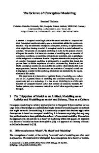
Figure 7. The three dimensions of the RE process.
Teledyne Brown Engineering, RMT from Marconi Systems Technology, and RDD100 from Ascent Logic. Pre-traceability has been investigated only recently [Gotel and Finkelstein 1994; Pohl 1996; Ramesh and Edwards 1993; Ramesh et al. 1995]. An interesting framework for requirements pre-traceability was provided by Pohl [1994] who described the requirements engineering process in a three dimensional space (see figure 7). The framework assumes that there are three major facets of the RE process, namely modelling the requirements in a more complete manner, modelling with more formality, and more consensus among stakeholders. These three facets lead to a three dimensions framework in which the process of requirements engineering can be traced: • The complexity of the individual/cognitive aspect of the RE process leads to the specification dimension which describes the degree of completeness of the requirements specification. • The social usage aspect leads to the agreement dimension which describes to what degree the members of the RE team agree on the requirements specification. • The system aspect leads to the representation dimension which describes how requirements are technically described, e.g., their degree of formal semantics. As shown in figure 7 the trace of the requirements engineering process is modelled as a path within the three dimensional space starting from an initial incomplete, informal specification representative of individual viewpoints and ending with the desired output which is a complete, fully agreed and formally described specification of the intended system. Capturing the RE process trace and thereby establishing requirements pretraceability means recording information along each of the three dimensions, on the relationships between the three kinds of information and relating those to actual process performance.
170
C. Rolland, N. Prakash / From conceptual modelling to RE
4.3. Computer tool support Conceptual modelling as part of system development is facilitated by the use of automated support in the form of CASE tools. A wide variety of CASE tools and CASE environments called Integrated CASE (ICASE) or Integrated Project Support Environment (IPSE) have been built to support specific methods. It has been pointed out [Norman and Forte 1992] that CASE tools have been successful in automating many routine tasks of system development. Wijers [1991] says that though the possible list of things that CASE tools can do is quite large, they have been essentially successful in providing documentation and verification support. Today’s tools therefore have excellent facilities for the editing and maintenance of graphical specifications but lack many functional features projected in CASE architectures like that of [Bubenko and Wangler 1992]. Some of these are to give support to distributed co-operative work, supporting integration in CASE, guiding the process of application development, incorporating reusable specification components, etc. Huang [1998] has also suggested some possible features for the next generation of CASE tools like process modelling, cross-platform portability, learning, standardisation, and access through the Internet. Traditionally, each method came with its own CASE tool. Application engineers were expected to select the method they wished to follow and used the associated CASE tool. If their application required even minor modifications in the methods/tools they had selected then it was not possible to make these changes. Thus, CASE technology was basically resistant to change. To sum up, tool support has been lacking in two main directions: (a) providing process support, and (b) adapting to the needs of specific systems. This motivated the approach shown in figure 8 which presents an architecture for process oriented RE support. The architecture is repository based. The repository extends the one advocated in Information Resource Dictionary Framework Standard [IRDS 1990]. Even though both consist of three levels, the difference is that whereas IRDS deals with levels of product description, the repository deals with levels of product and process descriptions [Brinkkemper 1990]. The environment is composed of two sub-environments, the application engineering environment in which the process is guided, executed, and traced, and the method engineering environment in which the process is defined and improved. These two environments use the process repository which contains the information necessary to provide the intended functionality. Thus, it can be seen that the architecture of figure 8 provides process support to application engineers and, additionally, establishes a link between application and method engineering through the repository. Tool support for requirements engineering is clearly a complex task. From the point of view of application engineering, it involves a number of different problems
C. Rolland, N. Prakash / From conceptual modelling to RE
171
Figure 8. Repository based and process-integrated environment support.
such as guidance, tracing, repository structuring and management, enactment mechanisms, efficient interpretation/execution of process modelling languages, configuration management, view integration, and co-operative development. The application engineering environment needs to support an exploratory process in such a way as to automate all routine, repetitive tasks so that attention can be devoted to exploring alternatives in elaborating the usage world. Additionally, it must help in bringing together the different stakeholders so that the final requirements can be arrived at in a collaborative manner. Finally, the environment must aid in the visualisation of the future system. Only a few of these functions have been implemented, for example, in prototypes such as PRO-ART [Pohl 1994] to support pre-traceability, MENTOR [Si-Said et al. 1996] which is a generic tool in the sense that it can function both as a method engineering tool and as a CASE tool depending upon the nature of the process model, PRIME-CREWS [Haumer et al. 1998] which offers a whiteboard editor for creating fine-grained traceability between goal models and multimedia artefacts, SAVRE [Sutcliffe et al. 1998] which guides in the generation of requirements to deal with system exceptions and the CREWS-L’Ecritoire [Tawbi et al. 1998] RE environment which has been built to provide guidance features. Over the last decade, method engineering has arisen as a separate field of study in itself. A number of CASE shells have been defined which consist of two parts, the Computer Assisted Method Engineering (CAME) and CASE generator part [Marttiin 1994]. A method is engineered by appropriate instantiation of the meta-model used in the CAME part. The CASE part uses this method to define the application engineering environment. Early CAME parts were organised around product meta-models and MetaEdit [Kelly et al. 1996] is an example of this. Efforts have been made to include process aspects in CAME using activity meta-models. When these are instantiated then the activities, tasks etc. performed by methods are also defined for the CAME
172
C. Rolland, N. Prakash / From conceptual modelling to RE
tool and Meta-Edit + [Kelly et al. 1996] is an example of that. More recently, a metamodel has been defined in terms of method components. In [Harmsen and Brinkkemper 1993] there are two kinds of components called fragments, namely product and process fragments whereas chunks in [Rolland et al. 1995] realise a tight process and product coupling. Method engineering is seen as a process of assembling together a method from its different fragments [Harmsen and Brinkkemper 1993; Plihon et al. 1998; Ralyte et al. 1999]. From the point of view of method engineering, tools must support the • • • •
selection of situated methods, i.e., methods meeting some contingency factors, creation of new methods rapidly when a completely new situation occurs, modification of existing methods to handle minor changes in methods, and assembly of situated methods from off the shelf method components to gain from past experience.
A feedback mechanism that allows application engineers to influence method definition and tool construction. 5.
Conclusion The thrust areas in requirements engineering are:
• embedding of systems in their larger usage context, and • change management. The former is made possible by stepping back from merely anticipating the functionality that a system must provide (as done in conceptual modelling) to the determination of this functionality in a systematic manner. This is done by identifying the aims and objectives of different stakeholders and the activities they carry out to meet these objectives. This stakeholder driven approach leads to better change management capabilities than found in conceptual modelling. This is because the RE product keeps track of the conceptual link between objectives, activities and system requirements. As a consequence of the shift to objectives and activities performed to meet them, almost all aspects of information systems engineering get affected. There is a new range of product models to directly represent these. The engineering processes involved are less prescriptive thereby supporting higher creativity and place an emphasis on learning from past experience. The supporting tools are directed on one hand, towards automation of routine tasks and towards providing direct guidance and support for discovering objectives and activities and on the other hand, towards process tracing in order to benefit from past experience. Guidance and tracing support needs to be provided in as transparent a way as possible. An environment is needed that provides a judicious mix of automated and semi-automated tools that perform routine, humdrum tasks while leaving important decision-making tasks to be done by the requirements engineer.
C. Rolland, N. Prakash / From conceptual modelling to RE
173
References Brinkkemper, S. (1990), “Formalisation of Information Systems Modelling,” Ph.D. Thesis, University of Nijmegen, Thesis Publishers, Amsterdam. Brunet J., C. Cauvet and L. Lasoudris (1990), “Why Using Events in a High-level Specification,” In Proceedings of the International Conference on Entity-Relationship Modelling, ER90, Lausanne, Switzerland. Bubenko, J.A. and B. Wangler (1992), “Research Directions in Conceptual Specification Development in Conceptual Modelling, Databases, and CASE,” In P. Loucopoulos and R. Zicari, Eds., Wiley, pp. 389–412. Bubenko, J.A. and M. Kirikova (1994), “Worlds in Requirements Acquisition an Modelling,” In 4th European–Japanese Seminar on Information Modelling and Knowledge Bases, Kangassalo and Wangler, Eds., Kista, Sweden, IOS. Bubenko, J., C. Rolland, P. Loucopoulos and V. De Antonnellis (1994), “Facilitating Fuzzy to Formal Requirements Modelling,” In Proc. Int. Conf. on Requirements Engineering (ICRE), Colorado Springs, USA. Curtis, B., H. Krasner and N. Iscoe (1988), “A Field Study of the Software Design Process for Large Systems,” Communications ACM 31, 11, 1268–1287. Dardenne, A., S. Fickas and A. van Lamsweerde (1991), “Goal-directed Concept Acquisition in Requirements Elicitation,” In Proc. 6th IEEE Workshop System Specification and Design, Como, Italy, pp. 14–21. Dardenne, A., A. van Laamsweerde and S. Fickas (1993), “Goal Directed Requirements Acquisition,” Science of Computer Programming 20, 1–2, 3–50. Desfray, P. (1994), Object Engineering, The Fourth Dimension, Addison-Wesley/Masson. DoD-2667A Military Standard (1988), “Defence System Software Development,” Department of Defence. Dowson, M. and C. Fernstrom (1994), “Towards Requirements for Enactment Mechanisms,” In Proc. European Workshop on Software Process Technology. Dubois, E., J. Hagelstein and A. Rifaut (1989), “Formal Requirements Engineering with ERAE,” Philips Journal of Research 43, 4. Feiler, P.H. and W.S. Humphrey (1993), “Software Process Development and Enactment: Concepts and Definitions,” In Proceedings of the Second Intl. Conf. on Software Process. Finkelstein, A., J. Kramer and M. Goedicke (1990), “ViewPoint Oriented Software Development,” In Proc. Conf. Le G´enie Logiciel et ses Applications, Toulouse, pp. 337–351. Franckson, M. and C. Peugeot (1991), “Specification of the Object and Process Modeling Language,” ESF Report No. D122-OPML-1. 0. Gotel, O. and A. Finkelstein (1994), “Modelling the Contribution Structure Underlying Requirements,” In Proc. First Int. Workshop on Requirements Engineering: Foundation of Software Quality, Utrecht, The Netherlands. Harker, S.D.P., K.D. Eason and J.E. Dobson (1993), “The Change and Evolution of Requirements as a Challenge to the Practice of Software Engineering,” In IEEE Symposium on Requirements Engineering, RE93, San Diego, CA, pp. 266–272. Harmsen, F. and S. Brinkkemper (1993), “Computer Aided Method Engineering Based on Existing MetaCase Technology,” In Proc. of the Fourth Workshop on the Next Generation of CASE Tools (NGCT93), Paris, France. Haumer, P., K. Pohl and K. Weidenhaupt (1998), “Requirements Elicitation and Validation with Real World Scenes,” IEEE Transactions on Software Engineering 24, 12. Huang, R. (1998), “Making Active CASE TOOLs – Towards the Next Generation of CASE Tools,” Software Engineering Notes 23, 1, 47–50. Humphrey, W.S. and M.I. Kellner (1989), “Software Process Modeling: Principles of Entity Process Models,” In Proc. 11th Int. Conf. on Software Engineering. IEEE-830 (1984), “Guide to Software Requirements Specification,” ANSI/IEEE Std 830.
174
C. Rolland, N. Prakash / From conceptual modelling to RE
IRDS, Information Resource Dictionary System (1990), “Framework,” ISO/IEC International Standard. Jackson, M., Ed. (1994), “Problems, Methods and Specialisation,” Special Issue of the SE Journal on Software Engineering in the Year 2001. Jackson, M. and P. Zave (1993), “Domain Descriptions,” In IEEE Symposium on Requirements Engineering, IEEE Computer Society Press, pp. 56–64. Jacobson, I. (1995), “The Use Case Construct in Object-Oriented Software Engineering,” In ScenarioBased Design: Envisioning Work and Technology in System Development, J.M. Carroll, Ed., Wiley, New York, pp. 309–336. Jarke, M. and K. Pohl (1993), “Establishing Visions in Context: Towards a Model of Requirements Processes,” In Proc. 12th Intl. Conf. Information Systems, Orlando, FL. Johnson, J. (1995), “Chaos: the Dollar Drain of IT Project Failures,” In Application Development Trends, pp. 41–47. Kardasis, P. and P. Loucopoulos (1998), “Aligning Legacy Information Systems to Business Processes,” In Proceedings of the 10th Conference on Advanced Information Systems Engineering, CAiSE98, Pisa, Italy. Kelly, S., K. Lyyttinen and M. Rossi (1996), “Meta-Edit+: A Fully Configurable, Multi-user and Multitool CASE and CAME Environment,” In Proceedings of the CAISE96 Conference, Springer-Verlag. Loucopoulos, P., V. Kavakli, N. Prekas, I. Dimitromanolaki, C. Yilmazturk, C. Rolland, G. Grosz, S. Nurcan, D. Beis and G. Vgontzas (1998), “The ELEKTRA Project: Enterprise Knowledge Modelling for Change in the Distribution Unit of Public Power Corporation,” In 2nd IMACS International Conference on Circuits, Systems and Computers (IMACS-CSC98), Athens, Greece, pp. 352–357. Lubars, M., C. Potts and C. Richer (1993), “A Review of the State of the Practice in Requirements Modeling,” In Proc. IEEE Symp. Requirements Engineering, San Diego. Martin, J. and J. Odell (1992), Object Oriented Analysis & Design, Prentice-Hall, Englewoods Cliffs, NJ. Marttiin, P. (1994), “Methodology Engineering in CASE Shells: Design Issue and Current Practice,” Ph.D. Thesis, Computer Science and Information Systems Reports, Technical Report TR-4. McGraw, K. and K. Harbison (1997), User Centered Requirements, The Scenario-Based Engineering Process, Lawrence Erlbaum Associates Publishers. Mylopoulos, J., L. Chung and B. Nixon, (1992), “Representing and Using Non Functional Requirements: A Process-oriented Approach,” IEEE Transactions Software Engineering 18, 6. Nardi, B.A. (1992), “The Use of Scenarios in Design,” SIGCHI Bulletin 24, 4. Norman, R. and G. Forte, Eds. (1992), “CASE in the 90’s,” Special Section of the CACM. Olle, T.W., J. Hagelstein, I.G. MacDonald, C. Rolland, H.G. Sol, F.J.M. Van Assche and A.A. VerrijnStuart (1988), Information Systems Methodologies: A Framework for Understanding, Addison-Wesley, Reading, MA. Plihon, V., J. Ralyt´e, A. Benjamen, N.A.M. Maiden, A. Sutcliffe, E. Dubois and P. Heymans (1998), “A Reuse-oriented Approach for the Construction of Scenario Based Methods,” In Proceedings of the International Software Process Associations 5th International Conference on Software Process (ICSP’98), Chicago. Pohl, K. (1994), “The Three Dimensions of Requirements Engineering: A Framework and Its Application,” Information Systems 19, 3, 243–258. Pohl, K. (1996), Process Centered Requirements Engineering, Wiley, New York. Potts, C. (1989), “A Generic Model for Representing Design Methods,” In Proc. 11th Int. Conf. on Software Engineering. Potts, C. (1997), “Fitness for Use: The System Quality that Matters Most,” In Proceedings of the Third International Workshop on Requirements Engineering: Foundations of Software Quality REFSQ’97, Barcelona, pp. 15–28. Prakash, N. (1997), “Towards A Formal Definition of Methods,” The Requirements Engineering Journal 23–50.
C. Rolland, N. Prakash / From conceptual modelling to RE
175
Prat, N. (1997), “Goal Formalisation and Classification for Requirements Engineering,” In Proceedings of the Third International Workshop on Requirements Engineering: Foundations of Software Quality REFSQ’97, Barcelona, pp. 145–156. Ralyte, J., C. Rolland and V. Plihon, Eds. (1999), Proceedings of the 11th Intl. Conf. On Advanced Information Systems Engineering (CAISE99), Springer-Verlag. Ramesh, B. (1993), “A Model of Requirements Traceability for Systems Development,” Technical Report, Naval Postgraduate School, Monterey, CA. Ramesh, B. and M. Edwards (1993), “Issues in the Development of a Requirements Traceability Model,” In Proc. IEEE Symp. on Requirements Engineering, IEEE Computer Society Press, San Diego, CA. Ramesh, B., T. Powers, C. Stubbs and M. Edwards (1995), “Implementing Requirements Traceability: A Case Study,” In Proceedings of the 2nd Symposium on Requirements Engineering (RE’95), UK, pp. 89–95. Rolland, C. and C. Ben Achour (1997), “Guiding the Construction of Textual Use Case Specifications,” Data & Knowledge Engineering Journal 25, 1, 125–160. Rolland, C. and C. Cauvet (1991), “ALECSI: An Expert System for Requirements Engineering,” In Proc. 3th Int. Conf. on Advanced Information Systems Engineering (CAISE’91), Springer-Verlag. Rolland, C. and N. Prakash (1994), “A Contextual Approach for the Requirements Engineering Process,” In Proc. Int. IEEE Conf. on Software Engineering and Knowledge Engineering (SEKE94), Riga. Rolland, C., C. Souveyet and M. Moreno (1995), “An Approach for Defining Ways-of-Working,” Information Systems Journal 20, 4, 337–359. Rolland, C., S. Nurcan and G. Grosz (1997), “A Way of Working for Change Processes,” In International Research Symposium ‘97 – Effective Organisations, Dorset, UK, pp. 201–204. Rolland, C., C. Souveyet and C. Ben Achour (1998a), “Guiding Goal Modelling using Scenarios,” IEEE Transactions on Software Engineering 24, 12, Special Issue on Scenario Management, 1055–1071. Rolland, C., P. Loucopoulos, V. Kavakli and S. Nurcan (1998b), “Intention Based Modelling of Organisational Change,” to appear. Rolland, C., C. Ben Achour, C. Cauvet, J. Ralyt´e, A. Sutcliffe, N.A.M. Maiden, M. Jarke, P. Haumer, K. Pohl, E. Dubois and P. Heymans (1998c), “A Proposal for a Scenario Classification Framework,” Requirements Engineering Journal 3, 1, 23–47. Rolland, C., N. Prakash and A. Benjamen (1999), “A Multi-model View of Process Modelling,” The Requirements Engineering Journal, to appear. Royce, W.W. (1970), “Managing the Development of Large Software Systems,” Proc. IEEE WESCON 08. Rumbaugh, J., M. Blaha, W. Premerlani, F. Eddy and W. Lorensen (1991), Object-oriented Modelling and Design, Prentice-Hall, Englewood Cliffs, NJ. Si-Said, S., C. Rolland and G. Grosz (1996), “MENTOR: A Computer Aided Requirements Engineering Environment,” In Proc 8th Int. Conf. on Advanced Information Systems Engineering (CAISE’96), Springer-Verlag. Sutcliffe, A.G. and N.A.M. Maiden (1994), “A Theory of Domain Knowledge for Requirements Engineering,” Nature Report Deliverable D-D-2. Sutcliffe, A.G., N.A.M. Maiden, S. Minocha and D. Manuel (1998), “Supporting Scenario-based Requirements Engineering,” IEEE Transactions on Software Engineering 24, 12, Special Issue on Scenario Management, 1072–1088. Tawbi, M., C. Souveyet and C. Rolland (1998), “L’ECRITOIRE – A Tool to Support a Goal-scenario Based Approach to Requirements Engineering,” Information and Software Technology Journal (under communication). The Standish Group (1995), Chaos, Standish Group Internal Report, http://www.standishgroup.com/chaos. html. Van Lamsweerde, A., R. Dairmont and P. Massonet (1995), “Goal Directed Elaboration of Requirements for a Meeting Scheduler: Problems and Lessons Learnt,” In Proc. of RE’95, 2nd Int. Symp. on Requirements Engineering, York, pp. 194 –204.
176
C. Rolland, N. Prakash / From conceptual modelling to RE
Wijers, G.M. (1991), “Modeling Support in Information Systems Development,” Ph.D. Thesis, Thesis Publishers, Amsterdam. Wynekoop, J.D. and N.L. Russo (1993), “System Development Methodologies: Unanswered Questions and the Research-practice Gap,” In Proc. of 14th ICIS, J.I. DeGross, R.P. Bostrom and D. Robey, Eds., pp. 181–190. Yourdon, E.E (1989), Modern Structured Analysis, Prentice-Hall, Englewood Cliffs, NJ. Yu, E.S.K and J. Mylopoulos (1994a), “Understanding Why in Software Process, Modelling, Analysis, and Desig,” In Proc. of the 16th International Conference on Software Engineering, Sorrento, Italy. Yu, E.S.K and J. Mylopoulos (1994b), “From ER to AR modelling Strategic Actor Relationships for Business Process Reengineering,” In Proc. of the 13th International Conference on the Entity–Relationship Approach, Manchester, UK. Yu, E.S.K and J. Mylopoulos (1994c), “Towards Modelling Strategic Actor Relationships for Information Systems Development – with Examples from Business Process Reengineering,” In Proc. of the 4th Workshop on Information Technologies and Systems, Vancouver, Canada.