Multi-domain System Models Integration for Faults Detection in Induction Motor Drives Constantin M. Apostoaia College of Engineering, Mathematics, & Science, Purdue University Calumet 2200 169th Street, Hammond, IN 46323, USA E-mail:
[email protected]
Abstract - The power electronic converters, electric machines, and mechanical loads are key parts of the electric drives systems, and these components are usually modeled and analyzed using specific simulation tools. The overall performances of the electric drives are influenced by system's interconnected components. One solution, to investigate the interaction between different parts of these multi-domain systems, is to integrate them into only one simulation environment. This paper presents the development of two integrated models of a three-phase induction motor (IM) drive: one, based on d-q machine model using MATLAB/SimulinkSimscape, the second being based on finite element analysis (FEA) motor model using ANSYS Simplorer/Maxwell software. The goal is to analyze the system models capabilities to simulate the faults detection caused by failures of different drive's components. The motor current signature analysis is used, in this paper, for monitoring the operation of the IM fed through a pulse-width-modulated (PWM) power inverter. Finally, two case studies are presented, one illustrating the effects of a faulty device of the PWM inverter, and the second case demonstrating the influence of the IM's stator fault. Another objective of this study is to provide users a convenient way of instruction in the area of faults detection and power quality of alternating current (ac) machines and drives. Keywords - PWM inverter, induction motor, FEA co-simulation, faults detection, engineering education.
I. INTRODUCTION The electric drives are multi-domain systems, with coupled non-linear components involving electric, electromagnetic and mechanical physical domains. The classic analytical design of the electric machines and drives, is now successfully complemented by using more realistic and accurate analysis and design methods based on FEA. The use of finite element method software become affordable, based on recent developments and increase of computational power, and is now a must for modeling, analysis and design of electric machines and drives [1]. The problem is that the electric machines, power electronic converters, and mechanical subsystems of the electric drives are modeled using specific separate software packages. Because the overall system performance is influenced by the interconnected components, the interaction between different parts of the drives must be analyzed. One solution is to integrate the models of all subsystems into only one simulation tool. The goal of this paper is to presents two such
integrated models of three-phase IM drives to be used for simulated faults detection and analysis. Two case studies are presented in order to illustrate the capability of the developed simulation platforms to detect faults due to electronic components failures of the drive's PWM inverter, and stator faults of the IM. Another objective of this work is to provide users a convenient way of instruction in the area of faults detection of induction motor drives based on current waveforms signature analysis. The motor current signature analysis is a condition monitoring technique that has been widely investigated in the literature [2], [3], [4]. Relevant advanced studies of the electric machines faults were reported by a team at Regal Beloit Corporation and University of Wisconsin Milwaukee [5]. Our initial work related to faults monitoring and detection, was based on the analysis of voltage and current waveforms distortion caused by failing electronic components of the brushless exciter of a high power wound field synchronous motor. In our preliminary studies [7], [8], FEA advanced machine models have been utilized to illustrate that faults of the ac machines can be also revealed by the magnetic field pattern variation. The development of the simulation platform, in this paper, is based on two different approaches that can be used for instructional materials in power and energy systems engineering programs. In our first approach, the development of the IM model is based on the state equations governing the motor dynamic operation. The following software products, adopted in this study, are required to build and simulate the overall model of the ac drive: MATLAB®, Simulink®, and Simscape [9]. The SimPowerSystems™, a product of Simscape toolbox, is first employed to model the PWM inverter, and Simulink is used to implement the state space model of the IM. The second approach, adopted in this study, is dedicated to advanced electric drives models. In this case, the linear simple machine models are not anymore sufficient in the analysis of control algorithms of ac drives with high dynamic performances. The motors’ behavior becomes more nonlinear depending on the drive changing conditions, and the effects of spatial harmonics and magnetic saturation on the control algorithms should be taken into account. In order to include these effects, advanced simulation tools are needed such as those centered on the FEA. The application of FEA for the ac machines simulation and design offers unlimited flexibility in
the geometrical shape, material properties, and boundary conditions in different regions of the machine [1]. In the second approach of this paper, the following products of the ANSYS commercial software are assumed to be available: RMxprt-Maxwell [10], which is required to build the accurate FEA model of the IM, and Simplorer [11], which is employed to implement the three-phase PWM inverter, the external electric circuit and the mechanical load. In the case studies presented in the paper the same threephase squirrel-cage induction motor is used for analysis. This is similar to the machine that has been adopted for use in the electric drives laboratory experiments proposed by the University of Minnesota within the nationwide consortium of universities CUSP [12]. The simulation results of the IM drive under normal and failure modes operating conditions are presented and compared using both proposed modeling methods. The paper is organized in five sections. In Introduction, the motivation of the simulation platform development is presented, and the work in progress elsewhere is discussed. In the second section, the two modeling approaches of the IM drive are presented. In the third section, the simulation results are displayed and analyzed. In fourth section, the use of simulation platforms for instruction in electric power engineering curriculum is shortly discussed. The fifth section outlines the concluding remarks and future work considerations. II. MODELING THE INDUCTION MOTOR DRIVES A. IM Drive Model in MATLAB/Simulink-Simscape In this section, a brief description of the state-space IM model is presented along with the corresponding block diagram realization in the Simulink-Simscape environment. The induction machine dynamic model chosen here is based on the space vectors theory and the following simplifying assumptions: three-phase symmetrical stator windings,
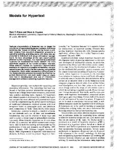
constant air gap, squirrel cage rotor, sinusoidal distribution of the air gap magnetic field (space harmonics neglected), machine operation in the linear region of the B-H curve (magnetic saturation neglected), and constant motor parameters. The rotor variables and parameters are referred to the stator winding, and the core losses are neglected. A fifth order dynamic state space model of the induction machine has been applied, in d-q synchronously rotating reference frame, and using the components of the stator and rotor flux space vectors and the rotor angular speed, [13], [14], [15]. The general state space IM model is conveniently used in studies of vector control and dynamic regimes of ac drives with induction motors. The best way to implement the IM mathematical model is based on Simulink block diagrams. The advantage is the easy access to all machine's state and output variables available in the internal structure of the built block diagram. For the open loop IM model implementation employed in this paper, the reference frame is stationary, fixed to the stator. Fig.1 illustrates the Simulink-SimPowerSystems block diagram realization of the open loop induction motor drive. The SimPowerSystems blocks are utilized for the nonlinear elements of the PWM inverter model: the MOSFET power transistors and the breakers (ideal switches) that are used to simulate a set of failure modes of the IM drive. The Simulink blocks are mainly utilized in the linear part of the diagram in Fig.1, for the state space induction motormechanical load subsystem model realization. Simulink blocks are also employed in the diagram of Fig.1 to generate the control gate signals of the three-phase PWM inverter. The three control voltages are compared with a switching-frequency triangular waveform to generate the switching functions for all six power transistors forming the switch-mode power electronic ac converter with three poles [15].
t
Continuous Ideal Sw itch pow ergui
Clock
Sw3
>= 0
Tem
g
D
g
D
D
g
Vab
Sw4 us_a
S
S
m
Tem m
S
= 0
+ v -
Vctrl 2
n_rpm
= 0 us_c