many cases, especially in the case of multi-hop transmissions, it would be .... As the schedule offsets in WiseMAC are unsynchronized, there is no common ...
Multi-Hop Cross-Layer Design in Wireless Sensor Networks: A Case Study Philipp Hurni, Torsten Braun Bharat K. Bhargava, Yu Zhang Institute of Computer Science and Applied Mathematics Department of Computer Sciences University of Bern, 3012 Bern, Switzerland Purdue University, West-Lafayette, IN 47906 {hurni, braun}@iam.unibe.ch {bb, zhangyu}@cs.purdue.edu Abstract—Cross-layer design has been proposed as a promising paradigm to tackle various problems of wireless communication systems. Recent research has led to a variety of protocols that rely on intensive interaction between different layers of the classical layered OSI protocol architecture. These protocols involve different layers and introduce new ideas how layers shall communicate and interact. In existing cross-layer approaches, the violation of the OSI architecture typically consists in passing information between different adjacent or non-adjacent layers of one single station’s protocol stack to solve an optimization problem and exploiting the dependencies between the layers. This paper proposes to go a step further and to consider cross-layer information exchange across different layers of multiple stations involved in multi-hop communication systems. It outlines possible application scenarios of this approach, and trades off between advantages and disadvantages of the proposed multi-hop crosslayer design. It examines an application scheme in a scenario of a wireless sensor network environment operating with a recent energy-efficient power saving protocol. Index Terms—Cross-Layer Design, Wireless Sensor Networks, Energy Efficient Medium Access Control
I. I NTRODUCTION Recently there has been increased interest in protocols for all kinds of wireless networks that rely on interaction and information exchange between various layers of the network stack. This design paradigm is often referred to as cross-layer design. It is often seen as a promising alternative to the classical layered view of a communication system. The main idea consists in actively exploiting the dependence between communication protocol layers, in order to obtain performance gains in respect to a certain goal, e.g. in terms of delay, jitter, throughput, energy efficiency or reliability. Especially in wireless ad hoc environments, cross-layer design can compensate for the unpredictable nature of the inherently unreliable wireless channel. Treating the entire communication protocol stack in a holistic manner can help in finding new means to alleviate the harmful performancerestraining consequences of common wireless network problems, such as burst errors due to channel distortions, wireless interference problems, multipath propagation or fading effects. In wireless sensor networks (WSNs), cross-layer design has been shown to significantly improve energy-efficiency. A WSN is a network consisting of distributed autonomous low-cost devices equipped with sensing hardware to monitor and report environmental values. Typically, WSNs report data wirelessly across multiple hops to a sink station. Energy-efficient, reliable and quick data delivery and data
processing are the main concerns in WSNs. Countless protocols targeting at different aspects of WSNs have been designed, implemented and evaluated he past few years. Especially in the field of energy-aware MAC protocols, many protocols apply optimization techniques based on cross-layer design. In [1], major improvements in terms of energy conservation are claimed by joint optimization of several tasks of the traditional layered OSI protocol architecture. This paper is organized as follows: Section II briefly introduces recent work on the paradigm of cross layer design and distinguishes it from the related concept of cognitive radio networks. Section III proposes and defines the concept of multi-hop cross-layer design and outlines possible applications scenarios. Section IV illustrates how this concept can be applied to achieve end-to-end QoS performance gains. In particular, we show that spreading and exploiting knowledge about specific MAC layer parameters of the energy-aware MAC protocol WiseMAC [2] to the routing layers of WSN nodes in the near neighborhood can help to achieve a lower end-to-end latency. Section V illustrates the simulation environment, experiment setup and discusses the obtained experimental results. Section VI concludes the paper. II. R ELATED W ORK A. Cross-Layer Design Recent research on cross-layer design has concentrated on specific aspects and problems of wireless communication systems. Srivastava et al. [3] provide an overview about the current state of the art in cross-layer design techniques and categorize the cross-layer techniques in a simple layer model according to the layers that are involved and the kind of interaction between the layers that are suggested. Illustrations a-d in Figure 1 point out the major categories of how the traditional layered OSI communication system model is violated in current crosslayer design studies. The main ideas behind them can be summarized as follows: a) Creation of new interfaces: new interfaces between adjacent and non-adjacent layers are introduced to enable information sharing at runtime. This permits to run optimization algorithms and exploit higher and/or lower layer information. b) Merging of adjacent layers: two or more layers are merged to one inseparable superlayer which runs an optimization algorithm and jointly takes care of all the former layer’s tasks.
Fig. 1: Different kinds of cross-layer design approaches
Fig. 2: Multi-hop cross-layer design
c) Vertical calibration across all layers: layer-specific parameters are read and manipulated across all layers. d) Completely new abstractions: as schematically depicted by a graph with bidirectional links instead of layers, some authors suggest to completely renounce the layer paradigm [4].
manipulates key parameters of the different protocol layers. The ability to learn from past behavior and decisions and the understanding that the layer boundaries are kept intact are particularly important to distinguish cognitive networks from cross-layer design approaches.
Melodia et al. similarly review recent work on cross layer approaches and design methodologies devised especially for WSNs in [5]. They classify the recent work according to the network layers that are involved and that are aimed to be replaced in the classical OSI network protocol stack. They conclude with general remarks on precautionary guidelines for cross-layer design approaches that should be considered to avoid unintended harmful consequences. The discussion about advantages and disadvantages of crosslayer design though is controversial. Some researchers claim substantial benefits of cross-layer design approaches targeting to solve typical wireless channel problems. Others are warning against the severe consequences of unrestricted and unattended coupling and interdependence between the network layers. Kawadia et al. [6] highlight the importance of solid architecture and modular design. The authors undermine that the layered modular architecture is a prerequisite for proliferation and standardization of technology, which after all guarantees its longevity. They warn researchers against the temptation to take architectural shortcuts to achieve short-term performance gains, as cross-layered protocol approaches without any sound architectural principles can quickly lead to unbridled chaotic spaghetti-design. They emphasize that with cross-layer design, layers can not be replaced and exchanged in case of software or hardware changes anymore because of increased layer dependencies. B. Cognitive Radio Networks Besides cross-layer design, cognitive radio and cognitive networks [7], [8] have become common buzzwords that are used to characterize the increased interaction among the traditional layers of the OSI architecture. A cognitive network is a network with a cognitive process that can perceive network conditions, and plan, decide and act on these conditions. It has the ability to learn from the impact of former adaptations and accordingly make future decisions, while taking into account end-to-end goals. Cognitive networks reach beyond the scope of cross-layer design, as they commonly perform multi-objective optimizations, whereas cross-layer designs typically focus on one optimization aspect. They pass current network observations to a so-called cognition layer, which
III. M ULTI - HOP C ROSS L AYER D ESIGN Obviously, the approaches summarized and outlined in [3] and illustrated in Figure 1 are limited to information exchange between the layers of one station’s protocol stack. New and maybe unorthodox cross-collaborations between upper and lower layers are introduced, but the measures taken remain limited to the layers of one active station in a communication system. Our suggestion is to consider and integrate intermediate nodes into the idea of cross-layer design and optimization. One can find more opportunities to exploit layerspecific information when extending the optimization techniques and algorithms to the layers of intermediate nodes. In many cases, especially in the case of multi-hop transmissions, it would be useful if the transport and routing layers were aware of the conditions and internal parameters of lower layers (MAC and physical layer) of the nodes in their near n-hop neighborhood. Possible application of lower layer knowledge or nearby neighbors are manifold: Nodes could detect signs of congestion, interferences, or irregularities in the transmission pattern early and immediately react to it on routing and transport layer. Congestion-aware routing protocols could rely their routing decisions on the additional lower layer knowledge. The especially harmful consequences of channel distortions in TCP over multi-hop wireless links could be addressed by exploiting MAC and physical layer knowledge in routing and transport layer of intermediate nodes. In wireless sensor networks with scarce energy resources, the problem to find energy- and latency-optimal channel allocation schemes and routing decisions could be addressed by providing more knowledge about the MAC and physical layer properties to the nodes’ routing and transport layers. Figure 2 illustrates the proposed concept of multi-hop crosslayer design. It depicts a source node, four intermediate nodes I1 , I2 , I3 , I4 and a destination node collaborating in a multihop communication system. Nodes are sharing MAC layer information with each other and passing it to the routing layers of their respective n-hop neighbors. In Figure 2, the parameter n is set to n = 4. For the ease of illustration, Figure 2 only illustrates the cross-layer information exchange between the MAC layer of the intermediate nodes to the routing layer of node S. The same collaboration and parameter exchange
however is assumed to take place between the intermediate nodes and their respective n-hop neighbors, too. The proposed scheme however differs from the cognitive network [7], [8] approach. Our suggestion is to allow information exchange between different layers of different nodes in multi-hop communication schemes. Cognitive networks may apply information exchange of lower layers across multiple stations, but they focus on the learning aspect and apply machine learning and artificial intelligence techniques in a socalled cognition layer to adapt layer parameters at run-time basically leaving the layered structure untouched. IV. A M ULTI - HOP C ROSS L AYER D ESIGN : A C ASE S TUDY IN A WSN E NVIRONMENT To give a simple example for the usefulness of the multihop cross-layer design concept, we focus on the application scenario of a wireless sensor network environment operating with an energy-aware MAC protocol. We address the question how much the end-to-end delay can be reduced by exploiting knowledge about MAC layer parameters that are actively disseminated farther than just to the corresponding MAC layer of their adjacent neighbors. Endowed with additional knowledge about the near n-hop neighborhood, nodes can optimize their routing decisions and choose delay-optimal paths when forwarding packets towards the sink node. A. WiseMAC The Wireless Sensor MAC (WiseMAC) [2] protocol belongs to the unscheduled sensor MAC protocols and is very energyefficient in scenarios with low or variable traffic. WiseMAC’s wake-up scheme consists of periodic duty cycles of only a few percent in order to sense the carrier for a preamble signal, as depicted in Figure 3. All nodes in the network sample the medium with a common basic cycle duration T, but their wake-up patterns are independent and left unsynchronized. When transmitting a frame, a preamble of variable length is prepended for alerting the receiving node in its wake-up interval not to go to the sleep state. When the receiver’s wake-up pattern is still unknown, the duration of the preamble equals the full basic cycle duration T, as illustrated in Figure 3 in the first transmission. The preamble is a simple bit sequence indicating an upcoming transmission to the node’s neighborhood. The own schedule offset is then piggybacked to the frame and transmitted to the receiver. After successful frame reception, the receiver node piggybacks its own schedule to the respective frame acknowledgment. Received schedule offsets of all neighbor nodes are subsequently kept in a table and are periodically updated. Based on this table, a
Fig. 3: WiseMAC
node can determine the wake-up patterns of all its neighbors, which in turn allows minimizing the preamble length for the upcoming transmissions. As the sender node is aware of the receiver’s wake-up pattern, it only prepends a preamble that compensates for the maximum clock drift that the two involved node’s clocks may have developed during the time since the last schedule exchange. As illustrated in Figure 3 in the second transmission, WiseMAC minimizes the preamble and calculates its duration as follows: Tpreamble = min(4θL, T ) θ denotes the quartz oscillator clock’s drift, L the time since the last update of the neighbor’s wake pattern and T the common basic cycle duration. B. Minimum Delay Routing using Multi-hop Cross Layer Information Sensor network nodes reporting data often have multiple different gateway nodes they can use to forward their packets. In lattice square networks, e.g. Figure 4, each node has two hop count optimal gateway nodes towards the sink, except for the nodes on the border. We assume that each node learns about the presence of its gateway nodes after network deployment by receiving and sending periodic beacons that contain the hop distance to the sink, in exactly the same manner as LMAC [9]. As the schedule offsets in WiseMAC are unsynchronized, there is no common wake-up schedule. Each node switches between receive and sleep state in its own proprietary tact. The goal of our multi-hop cross-layer case study consists in exploiting the knowledge about the different schedules exchanged over multiple hops to find a path from the source node S aiming to report data to the destination (sink) node D with a minimal end-to-end delay. Figure 4 illustrates the problem: the end-to-end delay for a transmission between source node S and destination node D can differ heavily, depending on whether S forwards the packet via its gateway node A1 or B1 . Two extreme cases are depicted in Figure 4. If the routing layer of node S is unaware of the MAC wake-up schedules of its adjacent neighbors, S has to rely the routing decision on the routing metric alone. However, both gateways A1 , B1 advertise the same cost towards the destination D, in terms of hop count. If node S chooses node B1 to forward its packets, the end-to-end delay ∆t is almost twice as long as by choosing A1 . When operating a simple shortest path metric based routing protocol on top of WiseMAC, and being completely unaware of the node’s MAC wake-up pattern, nodes are unable to optimize the packet transmission in terms of end-to-end latency and are condemned to make delay-suboptimal routing decisions. A simple cross-layer approach, consisting in providing an interface from the MAC layer of a node to the routing layer, will not suffice to solve the problem. Letting the routing layer access information about the next wake-up of the neighboring gateway nodes kept in the WiseMAC schedule offset table, as suggested by cross-layer design category a) in the taxonomy of Figure 1, might even be misleading. As displayed in Figure 4, the offset between packet generation of S and the next wakeup of B1 is smaller than the respective offset to A1 , although
(a) Lattice Square Network
(b) Delay on path S→A1 →A2 →A3 →D
(c) Delay on path S→B1 →B2 →B3 →D
Fig. 4: Minimizing end-to-end delay by exploiting multi-hop cross-layer information of nodes’ schedules the total delay on path S→B1 →B2 →B3 →D is bigger than on path S→A1 →A2 →A3 →D. If nodes would rely their routing decision on the wake-up patterns of only the 1-hop neighbors, nodes might choose the wrong gateway for forwarding the packet to the sink, in this case node B1 . In order to forward the packet over the minimum delay path, knowledge about the wake-up patterns of more than just the 1-hop neighbors is necessary. Source node S needs to be aware about the wakeup patterns of some first n intermediate nodes on the available paths to the destination node D, in order to find a route with a nearly optimal delay. In order to actually find the delay-optimal route, total knowledge of all node’s schedules would be necessary, even of nodes forming a route that is not optimal in terms of hopcount. As having total knowledge of all node’s wakeup schedules in each node of a sensor network would lead to an enormous search space for the optimization problem, not to mention the massive communication overhead to distribute the schedule information, we limit the search algorithm to the hopcount-optimal routes over the hopcount-optimal gateway nodes. In the following experimental Section V, we aim to find a suitable value for the lookahead parameter n by measuring the impact on the average end-to-end delay for multi-hop transmissions to the sink. C. Distributing wake-up patterns using beacons WiseMAC keeps the schedule offset table of the wake-up patterns of its 1-hop neighbors up to date using periodic beaconing. Depending on the routing scheme applied with WiseMAC, it might make sense to combine WiseMAC beacon functionality with HELLO or KEEPALIVE packets of the routing layer, e.g. in combination with on-demand routing protocols such as AODV or DSR. We let each node, including the source, broadcast beacon packets using WiseMAC fullpreamble broadcasts of duration T every Tbeacon seconds. Hop-count optimal paths will then be found within limited amount of time when each node appends its hopcount to its beacon. To distribute the wake-up patterns of the n-hop neighbors, each node shall continuously append its table of the schedule offsets of its respective (n-1)-hop neighbors, but only those that are on the path to the sink to its beacon, in order to limit the additional transmission and reception overhead. D. Calculation of minimum delay paths Let us denote a sequence of nodes N1 →N2 →· · · →Nk as path from N1 to Nk . Let us further define PSD (n) to be the set of
all subpaths of length n of all hop count optimal paths leading from node S towards node D. Let us further define d(P ) be the function that maps a path X to the respective delay over this path. The problem to find the minimum delay path given the knowledge of the wake-up schedules of all n-hop neighbor nodes can then be expressed as: X0 = argmin d(X) ∈ { X | X ∈ PSD (n)} Figure 5 illustrates how nodes calculate the minimum path for the example network topology in Figure 4, where node S aims to send a packet to node D. If we choose n = 1, nodes are aware of the wake-up patterns of the 1-hop neighbors. S will calculate the subpath towards its destination using its 1-hop neighborhood knowledge and obtain S→B1 = argmin d(X) ∈ PSD (1) and accordingly route the packet over B1 , as it offers the lower inter-delay to the next wake-up than the other minimum-hop gateway A1 . With n = 2, nodes are aware about the wake-up patterns of their 1-hop and 2-hop neighbors. S will calculate the subpath towards D and obtain S→A1 →A2 = argmin d(X) ∈ PSD (2) and accordingly route the packet over A1 instead of B1 . Increasing the knowledge-lookahead of MAC-specific information, in this particular case the wake-up pattern of WiseMAC on the routing layer of neighboring nodes, obviously leads to a totally different routing decision. When being aware of the wake-up schedules of the 1-hop neighbors, node S chooses B1 . Increasing the lookahead parameter to n = 2 however lets S choose the path over A1 to forward the packet. Accordingly, every intermediate node on the route between S and D performs the same calculation and relies its routing decision on its knowledge about the schedules of its near nhop neighbors. Using this routing scheme, we increase the probability that packet is routed over the minimum-delay path without having to keep and update knowledge about each intermediate node’s wake-up pattern concentrated in one single node. The optimization problem of minimizing the end-to-end delay is therefore solved in a distributed manner. Figure 5 illustrates that the complexity of the calculation of the minimum-delay path is O(g n ) where g is the fanout, the number of hop count optimal gateways a node can offer. Having an exponential computational complexity, the lookahead parameter n should be kept rather small.
Fig. 5: Calculation of minimum delay paths (for n = 1,2) V. P ERFORMANCE E VALUATION A. Simulation Environment We simulated 25 nodes arranged in a lattice square topology on an area of 200m x 200m using the OMNeT++ network simulator [10] and the mobility framework [11], which supports simulations of wireless ad hoc and mobile networks. It calculates SNR (Signal-to-Noise) ratios according to a free space propagation model basing on the equation for received power Pr of a node at distance d as Pr (d) =
Pt λ2 (4π)2 dα
where Pt is the transmitted signal power, λ the wavelength of the signal and α the path loss coefficient. The radio propagation allows to adjust the path loss coefficient α. Recent examinations of the signal attenuation in IEEE 802.11-based networks [12] conclude that a path loss coefficient between 3 and 4 is most suitable to model wireless propagation in office buildings and outdoor areas. Our simulations are based on a path loss coefficient of α = 3.5, as done in other sensor network simulations. For performance evaluation of powersaving MAC and protocols, one has to carefully model the transceiver’s energy consumption in its respective operation modes and state transition phases, as well as the transition delays and their respective costs. We used an energy consumption and state transition model with three operation modes sleep, receive and transmit, and applied the respective energy consumption values, transmission rate and state transition delays of the TR1001 low-power transceiver module [13], which is the transceiver chip of quite a few sensor hardware testbeds. The energy consumption model is based on the amount of energy that is used by the transceiver unit alone, CPU processing are not taken into account. Traffic is generated according to a Poisson model at the three most distant nodes from the sink in the lower right corner,
Fig. 6: 5x5 Lattice-square topology
marked S1 , S2 , S3 in Figure 6 and sent towards the sink node in the upper left corner. In a startup procedure of 100s, each node broadcasts beacons to discover its neighbors and receive path advertisements to the sink. After this bootstrapping procedure, the three nodes S1 , S2 and S3 start sending small data packets with size of 200 bits (including MAC and routing header) during 1h with a traffic intensity of λ = 0.05. transmission rate carrier frequency transmitter power sensitivity sensitivity carrier sensing communication range carrier sensing range path loss coefficient α WiseMAC basic interval duration T WiseMAC duty cycle WiseMAC beacon interval Tbeacon
19’200 bps 868 M Hz 0.1 mW -101.2 dBm -112 dBm 50 m 100 m 3.5 500 ms 1% (5 ms) 500 s
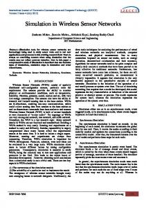
TABLE I: Simulation parameters B. Performance Results Figures 7 and 8 display the resulting one-way delay and the overall energy consumption of all the 25 nodes summed up for different values of n. In the case n = 0, routing is static and the routing layer is unaware of the wake-up pattern of the underlying MAC. As discussed in Section IV-C, every node broadcasts its distance with the WiseMAC beacons. Every node therefore receives path advertisements from its gateways. With n = 0, the routing layer selects one of its hop count optimal gateways at random and keeps forwarding its packet over this gateway for the whole simulation run. With n = 1, the routing layer is aware of the wake-up patterns of its 1hop neighbors, and always forwards the packet to the gateway with the soonest wake-up. With n > 1, the routing layer knows about the wake-up patterns of all the neighbors that are at maximum n-hops away. It calculates the shortest-delay gateway by exploiting the cross-layer information exchanged across n-hops, as proposed and described in Section IV-D. We observed a decrease in the average one-way delay of 21% when supplying the routing layers with the knowledge of their 1-hop neighbors. A simple interface from the routing layer to the WiseMAC schedule offset table suffices to achieve a oneway delay reduced by 21% . A further decrease of the delay by 30% compared to the static routing scheme could be observed when supplying the knowledge about the 2-hop neighborhood to each node’s routing layer. With n > 2, no additional benefit
Fig. 7: One-way delay could be measured, which however is likely to be different in bigger scenarios, where a higher benefit can be expected for the optimization problem. As illustrated in Figure 8, the overall energy consumption of all nodes does not differ heavily with varying values for n, and is within measurement variation. Costs for processing and computation of the minimum-delay subpaths with values as low as n = 2 can be considered negligible. The cost for exchanging WiseMAC schedules over some hops is considerably low, as the information to specify the sampling pattern of a node is small and does not change dynamically over time, as it would be the case with e.g. channel information. Sporadic refreshes of the offsets received by beacons suffice to keep this kind of multi-hop cross-layer information up to date. VI. C ONCLUSIONS This paper proposes the concept of multi-hop cross-layer design. Information exchange across multiple layers of multiple stations involved in multi-hop transmissions should be considered in the design of multi-hop wireless communication systems to achieve performance gains in respect to end-toend goals, such as throughput, latency or energy conservation. In a simple simulation scenario of a wireless sensor network environment operating with the power saving MAC protocol WiseMAC, the paper illustrates that applying the concept of multi-hop cross-layer design can help to solve distributed optimization problems and lead to performance gains. In particular, the analysis of a simple experiment shows that the exchange of specific MAC information of nodes with their n-hop neighborhood can improve the one-way delay of traffic routed across the network without having a measurable impact on the energy consumption. The experimental part concludes that for the given scenario, the parameter of n = 2 leads to a decrease in the end-to-end delay by roughly 30%. We propose to add the exchange of schedule information of nodes in the n-hop neighborhood as an additional feature to the WiseMAC protocol. Supplying these schedules as an optional service in the MAC interface provides an opportunity for the overlying layers to incorporate the wake-up schedules in order to make nearly delay-optimal routing decisions, and yet constitutes an adequate design. The lookahead parameter n should be determined experimentally for each application scenario and topology. ACKNOWLEDGEMENT This research has been supported by the 7th Framework Programme of the European Union under grant ICT-2008-224460
Fig. 8: Overall energy consumption (WISEBED) and grants ANI-0219110 and IIS-0209059 of the United States National Science Foundation (NSF). R EFERENCES [1] L. van Hoesel, T. Nieberg, J. Wu, and P. Havinga, “Prolonging the lifetime of wireless sensor networks by crosslayer interaction.” IEEE Wireless Communications, 2004. [2] A. El-Hoiydi and J.-D. Decotignie, “Wisemac: An ultra low power mac protocol for multihop wireless sensor networks.” ALGOSENSORS, 2004. [3] V. Srivastava and M. Motani, “Cross-layer design: A survey and the road ahead.” IEEE Communications Magazine, December 2005. [4] R. Braden, T. Faber, and M. Handley, “From protocol stack to protocol heap role-based architecture.” Hot Topics in Networking, 2002. [5] T. Melodia, M. C. Vuran, and D. Pompili, “The state of the art in cross-layer design for wireless sensor networks.” EuroNGI Workshops on Wireless and Mobility, 2005. [6] V. Kawadia and P. R. Kumar, “A cautionary perspective on cross layer design.” IEEE Wireless Communications, 2005. [7] R. Thomas, L. DaSilva, and A. B. MacKenzie, “Cognitive networks.” IEEE Intl. Symposium on New Frontiers in Dynamic Spectrum Access Networks, 2005. [8] R. Thomas, D. Friend, L. DaSilva, and MacKenzie, “Cognitive networks: adaptation and learning to achieve end-to-end performance objectives.” IEEE Communications Magazine, 2006. [9] S. Chatterjea, L. van Hoesel, and P. Havinga, “Lmac: an adaptive, information-centric and lightweight mac protocol for wireless sensor networks.” ISSNIP, 2004. [10] A. Varga, “The omnet++ discrete event simulation system.” European Simulation Multiconference, 2001, http://www.omnetpp.org. [11] W. Drytkiewicz, S. Sroka, V. Handziski, A. Koepke, and H. Karl, “A mobility framework for omnet++.” 3rd Intl. OMNeT++ Workshop, 2003, http://mobilityfw.sourceforge.net. [12] D. Faria, “Modeling signal attenuation in ieee 802.11 wireless lans.” Technical Report TR-KP06-0118, Stanford University, 2005. [13] RF Monolithics, “Tr1001 hybrid transceiver.” http://www.rfm.com/products/data/TR1001.pdf.