Multi-Linked AODV Routing Protocol for Wireless Mesh Networks Asad Amir Pirzada and Ryan Wishart
Marius Portmann†
Research Laboratory, National ICT Australia Limited, Brisbane, QLD 4000, Australia. {Asad.Pirzada, Ryan.Wishart}@nicta.com.au
School of Information Technology and Electrical Engineering, The University of Queensland, Australia, Brisbane, QLD 4072, Australia.
[email protected]
† Queensland
Abstract— Nodes in multi-hop wireless networks, and specifically in ad-hoc and mesh networks, are being increasingly equipped with multiple wireless network interfaces (radios) operating on orthogonal channels to achieve better utilisation of the frequency spectrum. In addition to reducing interference via increased channel diversity, these additional interfaces can be used to create multiple concurrent links between adjacent nodes, i.e. nodes within single-hop range of each other. Information about the availability of multiple links between nodes provides the opportunity to increase the overall performance of the network by optimally balancing traffic between the set of available internode links. In this paper, we present extensions to the well known Ad-hoc On-demand Distance Vector (AODV) routing protocol with the aim to discover and exploit multiple links in Wireless Mesh Networks. As demonstrated via extensive simulations, Multi-Link AODV (AODV-ML) achieves a more than 100% improvement over standard multi-radio AODV in terms of key performance metrics such as packet delivery ratio, latency and routing overhead.
Keywords: Multi-link, mesh, wireless, network, routing. I. I NTRODUCTION Mobile Ad-hoc Networks (MANET) and Wireless Mesh Networks (WMN) are self-organising and self-configuring wireless networks, typically implemented with IEEE 802.11 hardware. In conventional wireless LANs, clients communicate with access points via a single-hop wireless link and access points are interconnected via a wired backbone infrastructure. MANETs and WMNs do not rely on such a wired backhaul and implement connectivity via a multi-hop wireless network. Their robustness, self-organising and self-configuring nature, and the low cost of wide area deployment make them an attractive platform for a wide range of applications, such as public safety and emergency response communications, intelligent transportation systems, or community networks. Routing protocols are a key component in MANETs and WMNs, providing them with their self-configuration and selfhealing capabilities. These routing protocols endeavour to discover routes, traversing multiple hops, in a highly dynamic environment. These protocols can be broadly categorised into two types: Reactive and Proactive [1]. In reactive or ondemand routing protocols, the routes are established only when required, generally using flooding to discover routes in the network. In proactive routing protocols the routes are established before they are actually required, using periodical
exchanges of connectivity information. Both types of protocols have their individual advantages. Reactive protocols focus on minimising control packet overhead while the proactive protocols attempt to minimise the route establishment delays [2]. A fundamental problem of multi-hop wireless networks is the limited scalability and degradation of performance with increasing path lengths, i.e. number of hops. This limitation is mainly due to co-channel interference as well as the fact that IEEE 802.11 interfaces do not support full-duplex operation, i.e. simultaneous transmission and reception of data. One approach to overcome this problem is to use multi-homed (multi-radio) nodes, with radio transceivers tuned to orthogonal channels. Multi-homed nodes have significantly increased capacity, due to reduced interference and the ability to perform full-duplex communication, which is not supported by singleradio nodes. A number of reactive routing protocols have been proposed that are able to effectively discover routes in multi-radio wireless networks. Some of these protocols also support the discovery of multiple paths between node pairs. The most prominent examples of reactive routing protocols are Adhoc On-demand Distance Vector (AODV) [3] and Dynamic Source Routing (DSR) [4]. Reactive protocols establish a route between a source and a destination by broadcasting a Route Request packet in the network. The final destination or any other node with a valid and fresh route to the destination replies with a Route Reply packet which is sent back to the source via unicast. In the case of AODV, intermediary nodes remember these routes by creating routing table entries when these packets are forwarded. When Route Request packets are forwarded, reverse routes are created by creating a temporary routing table entry, associating the source address of the Route Request packet with the interface it was received on. When the corresponding Route Reply packets traverse back to the source, intermediary nodes create the corresponding forward routes, consisting of a routing table entry associating the source address of the Route Reply with the interface it was received on. DSR also uses a similar mechanism, but uses source routing whereby information regarding the entire path is added to
each packet at the source. The path information is collected during the flooding of Route Request packets and conveyed to the source using the Route Reply packet. Similar floodingbased route discovery mechanisms are used by most reactive routing protocols. However, none of the existing reactive routing protocols provides a mechanism for discovering all the available links between node pairs. Only a single link between two neighbour nodes is discovered. In case a link of an established route breaks, these protocols re-establish the route from scratch or at least trigger some repair mechanism that involves partial discovery of a new route, requiring the dissemination of routing packets in the network. In the same way, if a link gets congested due to local interference or increased traffic load, existing protocols do not offer an alternative way to resolve the problem locally and in real-time. Providing nodes with information about the complete set of links shared with each immediate neighbour allows resolving these problems locally, without involving an expensive route discovery process. In this case, traffic between two adjacent nodes can simply be redirected to an alternative link that is operational and/or less congested. In this paper, we present a variant of the AODV protocol that can successfully discover the set of available bi-directional links between adjacent nodes in a multi-hop wireless network. This discovery process is integrated with the route establishment process of the protocol and, therefore, achieves a high level of efficiency by incurring minimal overhead. The discovery mechanism is applicable to a wide range of multi-hop wireless networks, including highly heterogeneous networks with an arbitrary combination of single-radio/multi-radio and static/mobile nodes. Furthermore, the mechanism operates at the network layer and is independent of the physical and link layer, and can therefore support any type of network interface (or radio). The remainder of the paper is organised as follows. We first explain the standard and multi-link AODV protocols in Section II. The simulation results and their corresponding analysis are presented in Section III. Some related work is discussed in Section IV with concluding remarks in Section V. II. M ULTI -L INKED A D -H OC O N -D EMAND D ISTANCE V ECTOR ROUTING P ROTOCOL (AODV-ML) The AODV routing protocol is a reactive distance vector routing protocol that has been optimised for mobile ad-hoc wireless networks [5]. AODV borrows basic route establishment and maintenance mechanisms from the Dynamic Source Routing (DSR) protocol, and hop-to-hop routing vectors from the Destination-Sequenced Distance-Vector (DSDV) routing protocol [6]. To avoid the problem of routing loops, AODV makes extensive use of sequence numbers in control packets. When a source node intends to communicate with a destination node whose route is not known, it broadcasts a Route Request packet. Each Route Request contains an ID; source and destination node IP addresses and sequence numbers together with a hop-count and control flags.
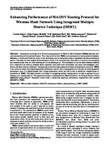
The ID field uniquely identifies the Route Request. The sequence numbers indicate the freshness of control packets, and the hop-count maintains the number of nodes between the source and the destination. Each recipient of the Route Request that has not seen the Source IP and Route Request ID pair, or does not maintain a fresher (with larger sequence number) route to the destination, rebroadcasts the same packet after incrementing the hop-count. Such intermediate nodes also create a reverse route to the source node for a certain interval of time. When the Route Request reaches the destination node, or any node that has a fresher route to the destination, a Route Reply packet is generated and unicast back to the source of the Route Request. Each Route Reply contains the destination sequence number, the source and the destination IP addresses, route lifetime together with a hop-count and control flags. Each intermediate node that receives the Route Reply, increments the hop-count, establishes a forward route to the source of the packet and transmits the packet on the reverse route. In case a link break is detected for a next hop of an active route, a Route Error packet is sent to its active neighbours that were using that particular route. The standard AODV protocol was originally developed for single-radio nodes in a wireless ad-hoc network. However, later on the protocol was modified to support nodes having multiple radios. We refer the standard AODV protocol with support for multiple radios as AODV-MR in this paper. When using AODV-MR, each Route Request is broadcast on all the node’s interfaces. Intermediate nodes with one or more interfaces operating on a common channel, receive the Route Request and create a reverse route that points towards the source node. If the Route Request is a duplicate, it is simply discarded. The first Route Request received by the destination, or any intermediary node, is selected and all subsequent Route Requests are discarded. The Route Reply is generated in response to the selected Route Request, and is sent back to the source node via the existing reverse route. Upon the completion of the AODV-MR route discovery process, all nodes forming a route are able to communicate with their adjacent nodes through a single link. This is also true for multi-homed nodes that communicate with other adjacent multi-homed nodes via a single link [7]. In contrast to AODV-MR, AODV-ML facilitates multihomed nodes to discover multiple concurrent bi-directional links between each other during the route establishment process of a reactive routing protocol. The discovery process is carried out in two stages, as shown in Fig. 1. The first stage is carried out when a source node floods the network with a Route Request packet in order to discover a route to the destination node. The source node broadcasts a Route Request packet on all its interfaces. Similarly, all intermediary nodes, which receive the same Route Request packet, rebroadcast the Route Request packet on all of their network interfaces. Depending upon the communication range, channel assignment, collisions or other factors, the destination or intermediate nodes may receive the Route Request packet
START
STAGE 1
SOURCE NODE
DURING ROUTE ESTABLISHMENT, SOURCE AND INTERMEDIATE NODES BROADCAST ROUTE REQUEST PACKETS ON ALL INTERFACES
FOR EACH INTERFACE A ROUTE REQUEST WAS RECEIVED ON, THE RECEIVING NODE CREATES A REVERSE LINK TO THE SENDING NODE
STAGE 2 DESTINATION AND INTERMEDIATE NODES UNICAST A ROUTE REPLY PACKET ON ONE OR MORE REVERSE LINKS CREATED IN STAGE 1
RECEIVING NODE CREATES ONE OR MORE FORWARD LINKS TO THE SENDING NODE BASED UPON THE INFORMATION DERIVED FROM THE ROUTE REPLY PACKETS
END
Fig. 1.
Two Stage Link Discovery Process
on one or more wireless interfaces. Nodes that receive the Route Request packet create a temporary “reverse link” to the adjacent node where the Route Request packet was received from. A reverse link may consist of an entry in a neighbour routing or link table, consisting of the identifier (e.g. IP address) of the adjacent node and the corresponding local network interface via which it can be reached. Separate reverse links are established for each interface on which a Route Request packet was received. This is in contrast to current reactive routing protocols, which only establish a single reverse link, required for the establishment of a single reverse route. Asymmetric or unidirectional links are not uncommon in wireless networks. Therefore, reverse links, which are created upon receipt of a Route Request packet, represent only unidirectional connectivity from the sender of the Route Request to the recipient. At this stage, the connectivity in the reverse direction has not been verified yet. A question that arises in this context is how do nodes differentiate between Route Request (or Reply) packets received from different nodes, and Route Request (or Reply) packets received from multiple interfaces of a single node? A number of solutions exist for this problem. First, we can configure
INTERMEDIATE NODE
INTERMEDIATE NODE
CONCURRENT LINKS
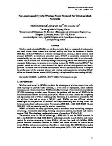
Fig. 2.
DESTINATION NODE
CONCURRENT LINKS
Multi-Links created using AODV-ML
all interfaces of a node to use the same IP address. We have implemented this approach in Linux and have used it in our simulations. Alternatively, node identifiers other than the IP address can be added to the Route Request and Route Reply packets, to determine which packets originate from the same node. The second stage of the discovery process is carried out when the destination node, or any intermediary node that has a valid route to the destination, responds to each Route Request packet received on a different interface with one or more Route Reply packets. The Route Reply is sent to the source of the Route Request using the reverse links created in Stage 1. When a Route Reply arrives at a node (intermediary or source), bidirectional connectivity is established to the node sending the Route Reply packet. Successful transmission in both directions of a link is required for a Route Request to be sent and the corresponding Route Reply to find its way back. At this stage, the corresponding entry for this link in the neighbour routing table is marked as established. Alternatively, instead of sending a Route Reply via all interfaces, a destination node could reply to a Route Request with a single Route Reply sent via a single interface only. In this case, the Route Reply needs to contain information about all the node’s interfaces to allow receiving nodes to figure out which common links (e.g. channels) they share. At the end of the two stage discovery process, all nodes involved in the route establishment have complete information about the available bidirectional links to their immediate neighbours. Fig. 2 illustrates the basic concept, showing the ranges of the individual radio interfaces as concentric circles. The source node on the left is single-homed and is hence only able to create a single bidirectional link with its adjacent node. The other nodes are multi-homed and discover multiple concurrent links to their immediate neighbours during the route establishment process of AODV-ML. These additional links can subsequently be used for a variety of applications without incurring any expensive route establishment or repair mechanisms. A few of these applications are outlined in the following: Link Repairing: In case a link between two adjacent nodes breaks, current reactive routing protocols generate a Route
33
45
20
51
52 13
36 53
54
7
25
42
56
57
58
43 62
35 66
71 40
68
65 3
73 17
4
Fig. 3.
AODV-MR and AODV-ML 900 seconds 1000 x 1000 m Two-ray Ground Reflection Random waypoint 0, 5, 10, 15 & 20 m/s 250 m CBR (UDP) 10, 20, 30, 40 & 50 128 kbps
70 47
18
75 48
III. S IMULATION R ESULTS AND A NALYSIS
39
24
32 74
49
50
10
69 44
11 72
28
27
9
23
67
46
64
2
22
5
60
12
34
Examined Protocol Simulation time Simulation area Propagation Model Mobility model for Mesh Clients Speed of Mesh Clients Transmission range Traffic Type No. of Flows Flow Rate
29
16
63
14
26
59
6 61
41
15
37
1
55 8
21
TABLE I TABLE 1: S IMULATION PARAMETERS
30
19
A. Simulation Environment 31
Mesh Network Topology
Error and a new route discovery is triggered either by the node observing the link breakage or the source node. However, AODV-ML makes it possible to retain multiple concurrent connections between adjacent nodes. A node observing a link breakage to an adjacent node can simply switch to an alternate link, without initiating route maintenance or discovery. Link Optimisation: The availability of concurrent bidirectional links between adjacent nodes permits effective channel optimisation. For example, interference on a path can be minimised by selecting links between nodes that have the least level of interference with upstream or downstream links, i.e. channel diversity can be increased. For example, if it is observed that the performance of a particular link is deteriorating due to increased interference, the node can switch to an alternative link with lower interference, thereby increasing the quality of service of the network. Load-Balancing: The availability of multiple concurrent bidirectional links also has a great potential for load-balancing. For example, if a node is unable to sustain the traffic flow on one of its links due to congestion, it can shift some of the load onto another parallel link in real-time. Striping: Striping at the network layer augments inter-node link capacity by sending traffic simultaneously on available links. Multiple concurrent links between adjacent multi-homed nodes can be bundled together to create a single high capacity virtual link [8]. In this paper we have simulated AODV-ML with support for link optimisation and repairing. To achieve link optimisation, AODV-ML endeavours to create routes traversing multi-homed nodes and using links tuned to orthogonal channels. In case one of the links goes down, that particular link is only marked as invalid and on-going traffic is simply switched to another link discovered earlier during the route discovery process. For details we refer the reader to our prior work on wireless mesh routing [9].
We have evaluated the efficiency of the AODV-ML protocol through extensive simulations in NS-2 [10], using the Extended Network Simulator (ENS) extensions [11]. For our simulations, we consider a hybrid WMN [12], consisting of both static Mesh Routers and mobile Mesh Clients. Each Mesh Client has a single 802.11b radio, while each Mesh Router is equipped with six 802.11b radios1 . The WMN covers an area of 1 square km and consists of 25 Mesh Routers and 50 Mesh Clients, as shown in Fig. 3. The Mesh Routers are distributed in a uniform 5x5 grid. Concurrent UDP flows are established between randomly selected source and destination Mesh Client pairs. The performance metrics are obtained by averaging the results from over fifty simulation runs. The simulation parameters are listed in Table I. B. Assumptions The following assumptions have been made: • • • • •
All radios are statically tuned to a channel. All Mesh Clients and Mesh Routers have a radio tuned to a common 802.11b channel. The remaining radios on the Mesh Routers are tuned to orthogonal 802.11b channels. The transmission and reception ranges of the wireless transceivers are equal. All antennae are omni-directional.
C. Mobility Model We use the random way point mobility model for the Mesh Clients in our simulation. Mesh Clients first wait for the pause interval, then move to a randomly chosen position with a velocity chosen randomly between 0 m/s and the maximum speed, wait there for the pause time, and then move on to the next random position. A maximum speed of 0 m/s corresponds to a completely static network. 1 Although, 802.11b can only support three orthogonal channels, we have configured the NS-2 802.11b physical layer to consider all channels to be orthogonal. This allows us to simulate the behaviour of radios that support a high number of orthogonal channels such as 802.11a.
12
100
AODV−MR AODV−ML
0.35
Routing Packet Overhead
80
70
60
Average Latency (seconds)
10
90 Packet Delivery Ratio (%)
0.4
AODV−MR AODV−ML
8
6
4
50
2
40 0
0 0
0.3 0.25 0.2 0.15 0.1 0.05
5
10 Maximum Speed
15
20
5
10 Maximum Speed
(a)
15
0 0
20
(b) 12
100
AODV−MR AODV−ML
90
10 Maximum Speed
15
20
(c) 0.7
AODV−MR AODV−ML
AODV−MR AODV−ML
0.6
10
70 60 50 40 30 20
Average Latency (seconds)
80
Routing Packet Overhead
Packet Delivery Ratio (%)
AODV−MR AODV−ML 5
8
6
4
2
0.5 0.4 0.3 0.2 0.1
10 0 10
20
30 Number of Connections
40
50
0 10
20
30 Number of Connections
(d)
40
(e)
Fig. 4.
50
0 10
20
30 Number of Connections
40
50
(f)
Simulation Results
D. Communication Model The IEEE 802.11 Distributed Coordination Function (DCF) [13] is used at the MAC layer. All packets are transmitted using the un-slotted Carrier Sense Multiple Access protocol with Collision Avoidance (CSMA/CA). In CSMA/CA each broadcasting node waits for a vacant channel by sensing the medium. If the channel is vacant, it makes the transmission. In case of a collision, the colliding stations wait using the Ethernet binary exponential back off algorithm [14]. Virtual Carrier Sensing (RTS/CTS) is disabled during the simulations. E. Performance Metrics The simulations provide the following three performance metrics: Packet Delivery Ratio: The ratio between the number of data packets successfully received by destination nodes and the total number of data packets sent by source nodes. Routing Packet Overhead: The ratio of control packets generated to successfully received data packets. Average Latency: The mean time (in seconds) taken by the data packets to reach their respective destinations. F. Results and Analysis The simulation results under varying Mesh Client speeds and traffic loads are shown in Fig. 4. In Figs. 4a, 4b and 4c the number of flows is fixed to 30 and the maximum Mesh Client speeds vary from 0 to 20 m/s. While in Figs. 4d, 4e and 4f the maximum speed of the Mesh Clients is fixed to 1 m/s and the number of flows is varied from 10 to 50. During route establishment, AODV-ML focuses on engaging minimally loaded channels for routing data traffic. This
helps to sustain the 30 simultaneous 128 kbps connections. However, AODV-MR forms routes over multiple hops by randomly selecting the available channels. Thus, a route may comprise of a large number of overlapping and saturated channels, resulting in severe packet losses. The lower packet losses incurred by AODV-ML enable it to achieve a significantly higher Packet Delivery Ratio (PDR) (Fig. 4a). The PDR of AODV-ML drops from 100% to almost 94% when the maximum Mesh Client speed increases from 0 to 20 m/s. The PDR of AODV-MR drops from 55% to 43% for a similar increase in Mesh Client speeds. However, when the number of simultaneous connections exceeds twenty (Fig. 4d), AODV-ML depicts a more than 100% improvement in PDR over the AODV-MR. Multi-homed nodes, when executing the AODV-MR protocol, form routes using a random interface rather than selecting an optimal interface. As a result, links frequently get saturated and suffer from interference. This essentially causes the routes to sever, thereby, causing new route discoveries. These route discoveries increase the routing overhead of AODV-MR to almost ten control packets for each data packet (Fig. 4b). On the other hand, AODV-ML selects optimal channels during the route establishment phase. This enables the route to be effective for longer durations, which minimises the need for extraneous route discoveries. The routes remain relatively stable at slow client speeds, which limit the number of route discovery floods. Thus we observe lower routing overhead for both protocols in a network sustaining 10 flows (Fig. 4e). However, as the number of connections is increased, the routing overhead of AODV-MR
increases significantly. On the other hand, AODV-ML is able to fix links locally (link repairing) and is thus able to minimise the routing overhead even under increased load conditions. As the routes created using AODV-ML have been optimised for minimal interference, packets are sent promptly without incurring excessive contention for the physical medium (Fig. 4c, 4f). This has the effect of reduced average latency of the data packets traversing an average of four hops. The packets flowing on routes established using AODV-MR face severe contention for the physical medium and are hence significantly delayed at each hop. IV. R ELATED W ORK The US patent by Wolman et. al. [15] and their related paper [16] discuss the establishment of a multi-radio unification protocol (MUP). The MUP presents multiple physical MAC addresses as a single virtual MAC address to the higher layers. The MUP multiplexes the packets from the higher layers on the appropriate network interface. Neighbour discovery is carried out using the standard Address Resolution Protocol (ARP), which informs nodes regarding the possible MAC addresses through which an adjacent node is accessible. Nodes broadcast an ARP request, asking the node with the given IP address to reply with its MAC address. If the node with the given IP address has multiple interfaces, each interface that receives a request will send an ARP reply, which allows the recipient to learn about its multiple links to that node. However, this method requires prior knowledge of the nodes and their IP addresses that a node wants to communicate with. This is an assumption which does not hold true for ad-hoc and wireless mesh networks, which are typically highly dynamic. MUP further provides the option for switching between the interfaces based upon the local channel interference. The major difference between the MUP and our work is the manner in which the multiple links are discovered. In MUP, the discovery of multiple concurrent bidirectional links to an adjacent node is carried out at the MAC layer using a single instance of the ARP process, while our work discovers multiple concurrent bidirectional links over multiple hops at the network layer using a single instance of the route establishment process. The other major difference is that the MUP is applicable only to static multi-hop wireless networks, while our work is applicable to any mobile multi-hop wireless networks, where the IP address of neighbours does not need to be known in advance. To the best of our knowledge, the discovery of multiple bidirectional links between nodes in a multi-hop wireless network that is tightly integrated with the route discovery process has not been covered earlier. V. C ONCLUSIONS In this paper, we have presented AODV-ML, a variant of the multi-radio AODV routing protocol, which discovers and utilises multiple links between multi-homed nodes in a wireless network. The proposed protocol can be applied to a wide range of multi-hop wireless networks, which consist of
multi-homed nodes, including mobile ad-hoc networks, sensor networks and wireless mesh networks. The most likely application is for wireless mesh networks, due to the fact that nodes in these networks are less resource constrained and more likely to be equipped with multiple network interfaces. With the help of extensive simulations, we found that by making optimal use of multiple links between nodes a significant improvement can be achieved in key performance metrics. The results show that under high mobility and traffic load conditions, AODVML provides an improvement of more than 100% in terms of packet delivery rate, latency and routing overhead over the standard multi-radio AODV routing protocol. ACKNOWLEDGEMENTS National ICT Australia is funded by the Australian Government’s Department of Communications, Information Technology, and the Arts and the Australian Research Council through Backing Australia’s Ability and the ICT Research Centre of Excellence programs and the Queensland Government. R EFERENCES [1] E. M. Royer and C. K. Toh, “A Review of Current Routing Protocols for Ad hoc Mobile Wireless Networks,” IEEE Personal Communications Magazine, vol. 6, no. 2, pp. 46–55, 1999. [2] A. A. Pirzada, C. McDonald, and A. Datta, “Performance Comparison of Trust-Based Reactive Routing Protocols,” IEEE Transactions on Mobile Computing, vol. 5, no. 6, pp. 695–710, 2006. [3] C. Perkins, E. M. Royer, and S. Das, “Ad hoc On-Demand Distance Vector (AODV) Routing,” IETF RFC 3561, 2003. [4] D. B. Johnson, D. A. Maltz, and Y. Hu, “The Dynamic Source Routing Protocol for Mobile Ad hoc Networks (DSR),” IETF MANET, Internet Draft, 2003. [5] J. Broch, D. A. Maltz, D. B. Johnson, Y. C. Hu, and J. Jetcheva, “A Performance Comparison of Multi-hop Wireless Ad hoc Network Routing Protocols,” in Proceedings of the 4th Annual International Conference on Mobile Computing and Networking (MobiCom). ACM Press, 1998, pp. 85–97. [6] C. E. Perkins and P. Bhagwat, “Highly Dynamic Destination-Sequenced Distance-Vector Routing (DSDV) for Mobile Computers,” in Proceedings of the SIGCOMM Conference on Communications, Architectures, Protocols and Applications. ACM Press, 1994, pp. 234–244. [7] A. A. Pirzada, M. Portmann, and J. Indulska, “Evaluation of MultiRadio Extensions to AODV for Wireless Mesh Networks,” in Proceedings of the 4th ACM International Workshop on Mobility Management and Wireless Access (MobiWac), 2006, pp. 45–51. [8] H. Adiseshu, G. Varghese, and G. M. Parulkar, “An architecture for packet-striping protocols,” ACM Transactions on Computer Systems, vol. 17, no. 4, pp. 249–287, 1999. [9] A. A. Pirzada, M. Portmann, and J. Indulska, “Hybrid Mesh Ad-hoc On-demand Distance Vector Routing Protocol,” in Proceedings of the Thirtieth Australasian Computer Science Conference (ACSC’07), vol. Vol 29, 2007, pp. 49–58. [10] NS, “The Network Simulator,” http://www.isi.edu/nsnam/ns/, 1989. [11] B. Raman and C. Chebrolu, “Design and Evaluation of a new MAC Protocol for Long-Distance 802.11 Mesh Networks,” in Proceedings of the 11th Annual International Conference on Mobile Computing and Networking (MobiCom). ACM Press, 2005, pp. 156–169. [12] I. F. Akyildiz and X. Wang, “A Survey on Wireless Mesh Networks,” IEEE Communications Magazine, vol. 43, no. 9, pp. S23–S30, 2005. [13] IEEE, “Wireless LAN Medium Access Control (MAC) and Physical Layer (PHY) Specifications 802.11,” 1997. [14] A. S. Tanenbaum, Computer Networks, 4th ed. Prentice Hall, 2002. [15] A. Wolman, A. Adya, P. Bahl, J. Padhye, and L. Zhou, “Multi-Radio Unification Protocol,” Patent 10/723 673, 2006. [16] A. Adya, P. Bahl, J. Padhye, A. Wolman, and L. Zhou, “A MultiRadio Unification Protocol for IEEE 802.11 Wireless Networks,” in Proceedings of the First International Conference on Broadband Networks (BROADNETS’04). IEEE Press, 2004, pp. 344–354.