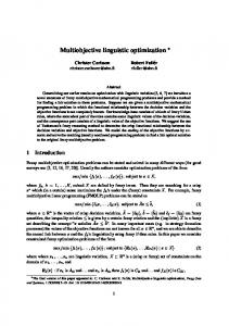
Multi-objective Optimization of Sensor Quality with Efficient Marine Vehicle Task Execution Michael Benjamin
Matthew Grund
Paul Newman
NAVSEA Division Newport RI CSAIL, MIT Cambridge MA e–mail:
[email protected]
Woods Hole Oceanographic Institution Advanced Engineering Laboratory Woods Hole, MA 02543 e–mail:
[email protected]
Robotics Research Group Oxford University, UK e–mail:
[email protected]
Abstract— This paper describes the in-field operation of two interacting autonomous marine vehicles to demonstrate the suitability of Interval Programming (IvP), a novel mathematical model for multiple-objective optimization. Broadly speaking, IvP coordinates competing control needs such as primary task execution that depends on a sufficient position estimate, and vehicle maneuvers that will improve that position estimate. In this work, vehicles cooperate to improve their position estimates using a sequence of vehicle-to-vehicle range estimates from acoustic modems. Coordinating primary task execution and sensor quality maintenance is a ubiquitous problem, especially in underwater marine vehicles. This work represents the first use of multiobjective optimization in a behavior-based architecture to address this problem.
I. I NTRODUCTION This work posits a solution to the problem of controlling an autonomous marine vehicle where control requirements are conflicted between primary task execution and maintaining a sufficiently accurate position estimate to facilitate primary task execution. We are motivated by the following scenario: two heterogenous vehicles are in operation, the first has a “survey at depth” role while the second shuttles location information from the Shuttle
salient survey information back to the surface. Data communications between the vehicles is by way of an acoustic modem which can also provide both one way and two way time of flight measurements between the vehicles. A single instance of the latter — a “ping”— provides range-only information constraining the relative locations of the vehicles to lie on an approximately spherical manifold. Initiating a sequence of pings from a well chosen sequence of locations (for example non-colinear when one vehicle is static) leads to a unique solution for the relative cartesian positions between vehicles. Control of the survey vehicle is composed of primarily two vehicle behaviors in a behavior-based control architecture. We utilize multi-objective optimization via the interval programming (IvP) model [1] for coordinating behaviors and discuss why this method of behavior coordination overcomes a well-known drawback of behavior-based systems. The problem of controlling a robot or autonomous vehicle in a manner that effectively balances task execution and maintaining accurate sensor-derived beliefs of its world is a ubiquitous problem not exclusive to marine vehicles, but is particularly prevalent in underwater vehicles. This work represents the first use of IvP in a behavior-based architecture to effectively address this problem. We present experimental validation of the architecture using autonomous kayaks and acoustic modems. II. BACKGROUND A. Behavior-Based Control
Survey
Fig. 1. Two heterogeneous unmanned marine vehicles are in operation. The first has a “survey at depth ” role while the second shuttles location information from the surface (GPS fixes) to the survey vehicle below and transports salient survey information from the first vehicle to the surface. Control of the “survey” vehicle is balanced between the need to survey, and the need to update the quality of its position estimate. Position updates come in the form of a sequence of range-only communications via acoustic modem.
surface (GPS fixes) to the survey vehicle below and transports
In behavior-based systems, robot or vehicle control is the result of set of independent, specialized modules working together to choose appropriate vehicle actions. It can be viewed as an alternative to the traditional sense-plan-act control loop as shown in Fig. 2, where decision-making and planning are performed on a single world model that is built up and maintained over time. Commonly cited virtues of behavior-based systems include: the ease of development of the independent modules, the lack of a single complex world model, and the potential for a highly reactive vehicle with certain behaviors triggered by the appropriate events in a dynamic environment. The origin of such systems is commonly attributed to Brooks’ “subsumption architecture” in [2]. Since then, it has
sense
World act
Best action for Behavior A
act
sense
Average of best two actions
Behavior Behavior
plan
Behavior
Combined effectiveness action selection
Fig. 2. Behavior-based control differs from conventional control by composing overall vehicle behavior into distict modules that are developed and operate largely in isolation, and coordinated through an action selection mechanism. In this case, action selection is in the form of a new multiobjective optimization technique to overcome known difficulties associated with behavior-based control.
been used in a large variety of applications including: indoor robots, e.g., [3], [4], [5], [6], [7], [8], [9], [10], [11], land vehicles, e.g., [12], planetary rovers, e.g., [13], [14], [15], and marine vehicles, e.g., [16], [17] [18], [19], [20], [21], [22]. Action selection, as indicated in Fig. 1, is the process of choosing a single action for execution, given the outputs of the behaviors. The “action space” is the set of all possible distinct actions. For example, all combinations of rotational and angular velocity for a robot, or all speed, heading and depth combinations for a marine vehicle. B. Known Difficulties in Behavior-Based Control The primary difficulty often associated with behavior-based control concerns action selection - namely how to ensure the chosen action really is in the best overall interest of the robot or vehicle. An action generally is a vector of values, one for each actuator being controlled. For example, the rotational and angular velocity for a land robot, or heading, speed and depth for a marine robot. Generally there are two techniques used in practice. The simplest method is to pick (at every iteration of the control loop) a single behavior to have exclusive control of the vehicle. Some approaches, like [18], [2], [23] assign a set of fixed priorities to behaviors, and conditions for their activation. The priorities do not change dynamically. In other implementations, like [20], priorities may be determined dynamically. Although appealing due to its simplicity, it is problematic in applications where the outright ignoring of the “secondary” behaviors leads to gross vehicle inefficiency, as is the situation with task described in this work. The other common form of action selection, known variably as “action averaging”, “vector summation” etc., takes the output of each behavior in the form of a vector and uses the average numerical value as the action sent to the vehicle’s actuators. Summation is typically weighted to reflect behavior priority. This method has been used effectively in a number of applications, [3], [24], [25], [19], [26]. When the preferred actions of two distinct behaviors disagree, this approach rests on the idea that the alternative actions degrade in effectiveness in a manner depicted in Fig.3. In such a case, the action, or actuator setting, in between the two individually preferred actions may indeed be the most effective
Possible settings for a single actuator
Fig. 3. In action-averaging, each behavior outputs a single best action. The best action presumably is the most effective among alternative actions for that particular behavior. The effectiveness levels of alternative actions are rendered here only for illustration and do not participate in the action averaging process. When two behaviors are non-mutually exclusive and share common action choices with high levels of effectiveness, as shown here, then action averaging typically reflects an appropriate compromise between behaviors.
action overall. However, action averaging is problematic in cases when alternative actions degrade in effectiveness in a manner depicted in Fig. 4, where the numerical average does not represent an effective compromise between two behaviors that are, in effect, mutually exclusive. Best action for Behavior A
Avg of best two actions
Best action for Behavior B
Utility
Model
Best action for Behavior B
Utility
World
Possible settings for a single actuator
Fig. 4. The average of the best action produced by two behaviors may have poor value for both behaviors. The chooser of the action is oblivious to the error since the behaviors output a single preferred action and not communicated the underlying effectiveness of their alternatives, rendered here only for illustration. In this case, the interests being pursued by the two behaviors are mutually exclusive, and the “compromise” is detrimental to both.
Even in cases where two behaviors are not mutually exclusive, where there do indeed exist actions that represent a good compromise, as shown in Fig. 5, action averaging can not guarantee the selection of the right action. In this work, such situations are typical between vehicle behaviors, and a new method of multi-objective optimization is applied to action selection to overcome this problem. III. T HE “I V P” A RCHITECTURE Here we describe the use of multi-objective optimization with interval programming and the two primary behaviors used in this experiment comprising task execution and maneuvers to update vehicle position estimate. A. Behavior-Based Control with Interval Programming By using multi-objective optimization in action selection, behaviors produce an objective function rather than a single preferred action ( [7], [12]). In the examples in Figs. 3 through 5, the objective functions are what distinguish opportunities for compromise. Note the pair of preferred actions in Figs. 3 and
Utility
Best action for Behavior A
Avg of best two actions
Best action for Behavior B
A good compromise
ranks candidate maneuvers with a utility that degrades linearly w.r.t. the candidate maneuver’s delta from the preferred heading and speed, as shown in Fig. 6. When this behavior is
Nearly best for B
Possible settings for a single actuator
Fig. 5. A multi-modal behavior is one where alternative actions exist that have high utility but actions “in between” have lower utility. For example a behavior where turning hard left or right is useful, but going straight is bad. In such situations, if only the single best action from each behavior is output, opportunities for effective compromise between two non-mutually exlusive behaviors is missed by simply averaging the two elite actions.
4 are virtually the same despite the differences in utility of secondary alternatives. There are two practical challenges in handling objective functions: (1) the method must be fast enough to accommodate the vehicle control loop, typically 1-20Hz. On each iteration new functions are created and a new problem solved (speed is a primary advantage of action averaging). (2) the method cannot be overly restrictive on objective function form. Nonconvex, multi-modal functions are quite common. The IvP model specifies (1) a scheme for representing functions of unlimited form and (2) a set of algorithms for finding the globally optimal solution. All functions are piecewise linearly defined, thus they are typically an approximation of a behavior’s true underlying utility function. Search is over the weighted sum of individual functions and uses branch and bound to search through the combination space of pieces rather than the decision space of actions. The only error introduced is in the discrepancy between a behavior’s true underlying utility function and the piecewise approximation produced to the solver. This error is preferable compared with the error of restricting all behaviors to a quadratic function for example. Furthermore, the search is much faster than brute force evaluation of the decision space, as done in [12]. The decision regarding function accuracy is a local decision to the behavior designer, who typically has insight into what is sufficient. The solver guarantees a globally optimal solution and this work validates that such search is feasible in a vehicle control loop of 4Hz on a 600MHz computer. To enhance search speed, the initial decision provided to the branch and bound algorithm is the output of the previous cycle, since typically what was a good thing to do a fraction of a second prior, is not a bad thing at the present. (In fact, when something does change dramatically in the world, such as hitting a way-point, the solve time has been observed to be roughly 50% longer, but still comfortably under practical constraints). B. Behavior for Executing a Survey Task The survey behavior drives the vehicle to a sequence of waypoints at a preferred speed. The produced objective function
Fig. 6. The survey behavior produces an objective function with peak utilities at the preferred heading and speed that would result in a traversal to the next area of interest in the survey. The utilities degrade linearly with the delta of a candidate decision. The utility function is parameterizable at mission planning time. The function is produced from scratch at each iteration of the control loop to reflect the new relative position of the vehicle to the area of interest in the survey.
run in isolation, it results in an un-conflicted set of maneuver legs comprising a survey as shown in Fig. 7. This particular survey mission pattern also represents the survey executed in our experimental results (alongside another behavior) shown in Fig. 8.
PIER
Fig. 7. The survey behavior, if run in isolation, will execute a series of legs governed by a set of way-points. The prevailing objective function ranks candidate maneuvers based on the next way-point. The objective function is shown here defined over candidate heading and speed where the darker points represent more preferred decisions.
1
C. Behavior for Resolving Position Uncertainty
120
120
100
100
80
80
60
60
40
40
20
20
0
0
−20
−20
−40
−40
0.9 0.8
We now describe the design and implementation of a behavior that ensures spatial diversity of ping-locations (the locations from which acoustic range information is requested via the acoustic modems). The goal is to enable the survey vehicle to gather enough information to locate (from a least squares adjustment or otherwise on a bundle of range measurements) the nav-aid vehicle which may or may not be moving. Using the entirety of the recorded ping-set is not a reasonable option given the latter possibility. This motivates making decisions in the light of a previous/local ping history. We label the set of the last n locations (out of N total pings) at which range information was recorded between the two vehicles ΩTn = [XN XN −1 · · · XN −n ]T . We are now faced with deciding where the next ping should occur from. This is a function of the shape of the locations in Ωn both in terms of their collective spatial extent and diversity. Consider, for example, the case where the points in Ωn form a line. It may be that this line is generally broadside to the nav-aid vehicle and naturally yields a tight solution. However a trajectory broadly co-linear with the nav-aid vehicle will lead to a poorly constrained solution. We adopt a motion governing behavior that seeks to produce spatially diverse set of measurement origins. The idea is to examine the principal directions of a tentative point set,Ωn0 , formed by augmenting Ωn with a new tentative observation point XN +1 . We proceed by forming the 2 × 2 covariance matrix , C, of this point set and define the minimum and maximum eigen-values of C as λ− and λ+ − respectively. The condition number of C, the ratio λλ+ , is an indication of the circular symmetry of Ωn0 — being unity for a perfect circle and zero for a perfectly co-linear point set. We also wish to take into account the size, or spatial extent of the point set. Consider the case where Ωn0 is small, almost round cluster (close to coincident) we do not wish to place a high utility in choosing a new putative observing point that would invoke no or little change in view point even if it would result in a Ωn0 with polar symmetry. Instead we would prefer to undertake a significant excursion away from − the original cluster despite the resulting reduction in λλ+ . We − encapsulate this preference by weighting the ratio λλ+ by a sigmoid function. This leads us to an expression of the utility u(XN +1 ) of visiting a new point XN +1 = (xN +1 , yN +1 ) given a recent history of N measurement locations ΩN : u(XN +1 ) =
λ− λ+ − α tanh( ) λ+ β
0.7 0.6 0.5 0.4 0.3 0.2 0.1 −60 300
−60 320
340
360
380
400
420
440
460
480
500
300
320
340
360
380
400
420
440
460
480
500
0
Fig. 8. The contours of the utility surface (in xy-space) of obtaining a new “ping” from a new location conditioned on two illustrative distributions of previous “ping” locations. The linear distributions on the left produces two symmetric peaks. Moving to either one would substantially increase the spatial diversity and importantly resolve potential left/right ambiguity resulting from linear motion with range only measurements. The circular distribution on in the right hand plot yields a polar-symmetric utility surface - no one direction is preferred over another any substantial (but not excessive) radial motion will satisfy the desire to range from a maximally spatial diverse set of locations
IV. T HE E XPERIMENT S ETUP For experimental validation of the architecture two autonomous kayaks fitted with acoustic modems were used. A. Behavior Configuration The two behaviors described in the previous section were configured in a manner that retained a steady priority weight for the survey behavior, and a varying priority weight for the behavior for resolving position uncertainty. When the position uncertainty became higher, the “resolve” behavior grew in priority until the vehicle sufficiently maneuvered to reduce uncertainty via an acoustic modem communication. B. Acoustic Communication and Acoustic Telemetry
(1)
here α and β parameterize the “break point” and knee width of the sigmoid function respectively. The experimental results presented in this paper use marine surface craft, so Ω has so far been considered to be set of 2D points. However Equation 1 is equally applicable to the 3D x, y, z measurement positions that result from Autonomous Underwater Vehicle (AUV) operations.
Fig. 9. Basic WHOI Micro-modem board set: power amp and main board. In this simple low-power configuration, the modem communicates using Frequency-Hopping Frequency Shift Keying (FH-FSK) at a burst rate of 80bps. At 25KHz, the modem can communicate at ranges greater than 2km, in the challenging Very Shallow Water environment.
The autonomous vehicles are equipped with WHOI Micromodems which can provide acoustic telemetry and ranging. The modem is a small low-power design based around the
TABLE I WHOI M ICRO - MODEM S PECIFICATIONS Spec.
802.11b Antenna
Description
Units
PRX
Power consumption while receiving
80 mW
PT X
Power consumption while transmitting
10 W
SP LT X
Transmitter sound pressure level
192 dB re µ Pa
∆TRX
Receiver timing resolution
125 µ sec
rF SK
FSK data rate
80 bps
BF SK
FSK packet data payload
32 bytes
TF SK
FSK packet duration
3.2 seconds
Nnodes
Maximum number of nodes per subnet
16 nodes
fc
Band C center frequency
25KHz
BWc
Band C Bandwidth
4 KHz
Texas Instruments TMS320C5416 fixed-point DSP, as shown in Fig. 9. The Micro-modem was designed for autonomous vehicles and long term sub-sea deployed systems [27]. Its specifications are summarized in table I. The modem provides access to a half-duplex underwater acoustic channel using a time-domain multiple access (TDMA) scheme [28]. Telemetry packet transmissions are scheduled using a short (1.1 second duration) cycle initialization (CI) packet, followed shortly thereafter with a longer telemetry packet. Typically, one modem implements a schedule by transmitting CI packets, and all modems in the subnet observe the schedule, transmitting their telemetry when commanded, and receiving otherwise. This allows modem users to share their telemetry across the acoustic subnet, in synchronized broadcast fashion. Because telemetry packets have small (32 byte) data payloads, a library of compressed binary messages called the Compact Control Language (CCL) has been developed [29]. This library has been expanded to include a UTM navigation message, for transmitting high precision vehicle location information to another platform. This new CCL message was used to convey the “shuttle” kayak’s position estimate to the “survey” kayak. In addition, the Micromodem is capable of acoustic navigation. Networks of acoustic transponders can be interrogated, estimating range via travel-time measurements, and modems can estimate range to each other, using an acoustic network ping packet. In this experiment, short ping packets (also 1.1 second duration) were used to estimate range between the autonomous kayaks. C. The Marine Vehicle Platforms Experimental validation is done on four kayak-based autonomous surface crafts depicted in Fig. 10. See [30] for more details on this platform. V. E XPERIMENTAL R ESULTS Two Kayaks, fitted with acoustic modems were used to generate the results in this section. One vehicle which will ultimately play the role of the nav-aid vehicle remained still
Cool Water Circulated Cooling System
Kill Switch
Main vehicle computer in Watertight Enclosure
Fig. 10.
A kayak-based autonomous surface craft.
at the origin while the other took the role of the survey vehicle. The latter executed a trajectory determined by the interplay of two, sometimes contradictory behaviors, described in Sections III-B and III-C — the desire to execute a simple survey pattern (in this case a “box”) and also the desire to add spatial diversity to the locations from which vehicle to vehicle ranging occurs. The latter “resolve” behavior running on the survey vehicle is modulated by a quality metric, η, of its own onboard navigation. In the field this may be for example horizontal dilution of precision (HDOP) or the volume of its 1sigma position uncertainty ellipsoid. When the quality metric is low, greater importance is attached to obtaining a nav-fix by ranging to and communicating with the nav-aid vehicle. However, to obtain such a fix while avoiding the singular configurations and left-right ambiguities that plague rangeonly estimation, spatial diversity is required - precisely what the “resolve” behavior was designed to instigate. In Figure 11 we paint the trajectory of the vehicle with color to denote the onboard navigation quality metric. Blue and red represent high and low navigational confidence respectively which accord low and high importance to the resolve behavior. In short, when the trajectory is shaded red the motivation to execute a “wiggle” is increased over that when it is blue. The experimental arena (a large river) was not sufficiently large to allow a genuine degradation of navigation to accumulate over time. Instead the evolution η was simulated by a zero to unity ramp with a period of 60 seconds. Although crude, this approach does aid clarity while illustrating the efficacy of the IvP framework in terms of action selection. In particular the importance attached a particular behavior is not coupled to the effect it has on the system at large which would be the case if the resolve behavior really had an effect on η.
Around the perimeter of Figure 11 a selection of utility surfaces are rendered. Each depicts the utility associated with achieving one more ping from a x, y position conditioned upon the set of locations from which the survey vehicle has recently pinged the stationary nav-aid vehicle. The recent ping locations are shown as white dots superimposed over the utility surfaces. Note how the value of η modulates the overall utility. For example at point 20 the utility of a course change to diversify ping-locations is small because the vehicle possesses a high degree of confidence in its position estimates. on the other hand at point 17 the converse is true and we see a perturbation occurring in the ensuing vehicle path. The straight line in the south east corner is a result of an extended period of failed acoustics. With so few recent ping-locations pinging from anywhere results in significant spatial diversity and so the vehicle simply executes the unadulterated baseline survey behavior without perturbation. VI. C ONCLUSIONS In this work we have applied a novel method for executing multi-objective optimization on a marine vehicle platform and shown its suitability in resolving conflicts between sensor requirements and primary task completion in the marine environment. Although this work has demonstrated that a sensor optimization behavior and survey behavior can both be satisfied, much practical work remains to implement a robust solution for underwater vehicles operating in the ocean environment. For example, underwater survey sensors such as sidescan sonars and cameras have different behavioral constraints from the survey behavior presented here. Also, the navigation sensor optimization behavior should rely on observed variables such as acoustic link quality, and navigation solution quality estimates. ACKNOWLEDGEMENTS The WHOI acoustic modem navigation capabilities were developed under the U.S Office of Naval Research AOFNC program, contract number No. N00014-02-C-0201 managed by Jim Valentine and Tom Curtin. This work was funded in part by ONR NICOP Program, contract No. N00014-0510311 managed by Donald Wagner and Jim Greenberg, as well as by the NUWC Division Newport ILIR program managed by Dick Philips. The authors also wish to thank Joe Curcio, the designer and builder of the kayak platforms used in our experiments, and John Leonard and Lee Freitag for support in this cross-discipline venture. R EFERENCES [1] M. R. Benjamin, “The Interval Programming Model for Multi-Objective Decision Making,” Computer Science and Artificial Intelligence Laboratory, MIT, Cambridge, MA, Tech. Rep. AIM-2004-021, September 2004. [2] R. A. Brooks, “A Robust Layered Control System for a Mobile Robot,” IEEE Journal of Robotics and Automation, vol. RA-2, no. 1, pp. 14–23, April 1986. [3] R. C. Arkin, “Motor Schema Based Navigation for a Mobile Robot: An Approach to Programming by Behavior,” in Proceedings of the IEEE Conference on Robotics and Automation, Raleigh, NC, 1987, pp. 264– 271.
[4] R. C. Arkin, W. M. Carter, and D. C. Mackenzie, “Active Avoidance: Escape and Dodging Behaviors for Reactive Control,” International Journal of Pattern Recognition and Artificial Intelligence, vol. 5, no. 1, pp. 175–192, 1993. [5] J. Hoff and G. Bekey, “An Architecture for Behavior Coordination Learning,” in Proceedings of the 1995 IEEE International Conference on Neural Networks, Perth, Australia, November 1995, pp. 2375–2380. [6] S. Lenser, J. Bruce, and M. Veloso, “A Modular Hierarchical BehaviorBased Architecture,” in RoboCup-2001: The Fifth RoboCup Competitions and Conferences, A. Birk, S. Coradeschi, and S. Takokoro, Eds. Springer Verlag, 2002. [7] P. Pirjanian, “Multiple Objective Action Selection and Behavior Fusion,” Ph.D. dissertation, Aalborg University, 1998. [8] J. Riekki, “Reactive Task Execution of a Mobile Robot,” Ph.D. dissertation, Oulu University, 1999. [9] A. Saffiotti, E. H. Ruspini, and K. Konolige, “Using Fuzzy Logic for Mobile Robot Control,” in Practical Applications of Fuzzy Technologies, H. J. Zimmerman, Ed. Kluwer Academic Publishers, 1999, ch. 5, pp. 185–206. [10] E. Tunstel, “Coordination of Distributed Fuzzy Behaviors in Mobile Robot Control,” in IEEE International Conference on Systems, Man, and Cybernetics, Vancouver, BC, Canada, October 1995, pp. 4009–4014. [11] M. Veloso, E. Winner, S. Lenser, J. Bruce, and T. Balch, “Visionservoed Localization and Behavior-Based Planning for an Autonomous Quadruped Legged Robot,” in Proceedings of AIPS-2000, Breckenridge, April 2000. [12] J. K. Rosenblatt, “DAMN: A Distributed Architecture for Mobile Navigation,” Ph.D. dissertation, Carnegie Mellon University, Pittsburgh, PA, 1997. [13] H.-H. Ju, P.-Y. Cui, and H.-T. Cui, “Autonomous Behavior Path Planning for Lunar Rover,” ACTA AUTOMATICA SINICA, vol. 29, no. 2, pp. 324– 329, 2002. [14] P. Pirjanian, T. L. Huntsberger, and P. S. Schenker, “Development of CAMPOUT and its further applications to planetary rover operations: a multi-robot control architecture,” in Proceedings of SPIE Conference on Sensor Fusion and Decentralized Control in Robotic Systems IV, Newton, MA, October 2001. [15] S. Singh, R. Simmons, T. Smith, A. Stentz, V. Verma, A. Yahja, and K. Schwehr, “Recent Progress in Local and Global Traversability for Planetary Rovers,” in IEEE Conference on Robotics and Automation, San Francisco, CA, April 2000. [16] M. R. Benjamin, “Multi-objective Autonomous Vehicle Navigation in the Presence of Cooperative and Adversarial Moving Contacts,” in OCEANS 2002, Biloxi Mississippi, October 2002. [17] M. Benjamin, J. Curcio, J. Leonard, and P. Newman, “Navigation of Unmanned Marine Vehicles in Accordance with the Rules of the Road,” in International Conference on Robotics and Automation (ICRA), Orlando, Florida, May 2006. [18] A. A. Bennet and J. J. Leonard, “A Behavior-Based Approach to Adaptive Feature Detection and Following with Autonomous Underwater Vehicles,” IEEE Journal of Oceanic Engineering, vol. 25, no. 2, pp. 213–226, April 2000. [19] M. Carreras, J. Batlle, and P. Ridao, “Reactive Control of an AUV Using Motor Schemas,” in International Conference on Quality Control, Automation and Robotics, Cluj Napoca, Rumania, May 2000. [20] R. Kumar and J. A. Stover, “A Behavior-Based Intelligent Control Architecture with Application to Coordination of Multiple Underwater Vehicles,” IEEE Transactions on Systems, Man, and Cybernetics - Part A: Cybernetics, vol. 30, no. 6, pp. 767–784, November 2001. [21] J. K. Rosenblatt, S. B. Williams, and H. Durrant-Whyte, “BehaviorBased Control for Autonomous Underwater Exploration,” International Journal of Information Sciences, vol. 145, no. 1-2, pp. 69–87, 2002. [22] S. B. Williams, P. Newman, G. Dissanayake, J. K. Rosenblatt, and H. Durrant-Whyte, “A decoupled, distributed AUV control architecture,” in Proceedings of 31st International Symposium on Robotics, Montreal, 2000. [23] P. M. Newman, “MOOS - A Mission Oriented Operating Suite,” MIT Department of Ocean Engineering, Tech. Rep. OE2003-07, 2003. [24] R. C. Arkin and T. Balch, “AuRA: Principles and Practice In Review,” Journal of Experimental and Theoretical Artificial Intelligence, vol. 9, pp. 175–189, 1997. [25] T. Balch and R. C. Arkin, “Behavior-Based Formation Control for Multiagent Robot Teams,” IEEE Transactions on Robotics and Automation, December 1998.
Fig. 11. A rendering of the experimental results. The vehicle (an autonomous Kayak see Figure 10) executes a meandering trajectory under the influence of two behaviors running in the IvP framework. One behavior is set on marshalling the vehicle around a rectangular survey pattern similar to that in Figure 7. The second behavior is more complex. It continually considers the spatial diversity of the most recent sites from which acoustic ranges to the companion vehicle are obtained. In the light of this it produces a utility or objective function over (x,y) space (which is later mapped to the course, speed and time action space) scored in proportion to the degree of increase spatial diversity which be afforded by acquiring a new range measurement at each x, y location. A few examples of the utility functions generated at various times around the circuit are plotted in independent axes around the perimeter. The overall weight/importance of the behavior is mediated by the confidence the vehicle has in its own navigation. In this way, when unsure of its own position the vehicle is motivated to move in a way to increase the quality of a navigation update from the nav-aid vehicle sitting at the origin. The vehicle trajectory is colored in proportion to this confidence metric — blue high, red low. The straight section in the south east corner is due to a temporary drop in the rate of successful two way range measurements - with so few recent ping locations any motion produces spatial diversity and the preferred linear motion of the survey behavior is un-opposed.
[26] O. Khatib, “Real-Time Obstacle Avoidance for Manipulators and Mobile Robots,” in Proceedings of the IEEE International Conference on Robotics and Automation, St. Louis, MO, 1985, pp. 500–505. [27] L. Freitag, M. Grund, S. Singh, J. Partan, and K. Ball, “The WHOI Micro-Modem: An Acoustic Communications and Navigation System for Multiple Platforms,” in IEEE OCEANS, Washington DC, 2005. [28] L. Freitag, M. Johnson, and M. Grund, “Integrated Acoustic Communication and Navigation for Multiple AUVs,” in IEEE OCEANS, Honolulu, October 2001, pp. 2065–2070. [29] R. P. Stokey, “A Compact Control Language for Autonomous Underwater Vehicles,” Woods Hole Oceanographic Institution, Tech. Rep., 2005. [30] J. Curcio, J. Leonard, and A. Patrikalakis, “SCOUT - A Low Cost Autonomous Surface Platform for Research in Cooperative Autonomy,” in OCEANS 2005, Washington DC, September 2005.