floating-point algorithm to fixed-point is time-consuming and .... to calculate Ishift and Cscale as follows. ... flow, resulting in unnecessary shifts of an operand.
MULTI-OPERAND BLOCK-FLOATING POINT ARITHMETIC FOR IMAGE PROCESSING A. Lipchin, I. Reyzin, D.Lisin, M.Saptharishi VideoIQ, Inc 213 Burlington Road, Bedford, MA 01730 {alipchin, ireyzin, dlisin, msaptharishi}@videoiq.com ABSTRACT We extend the application of block-floating point arrays to multi-operand algebraic expressions consisting of additions and multiplications. The proposed method enables automatic runtime calculation of binary shifts of array elements. The shifts are computed for all elementary operations in an expression using a dataflow graph. The method attempts to preserve accuracy across the entire expression while avoiding overflow. A variety of common computer vision and image processing operations can be efficiently realized in fixedpoint processors using the proposed technique. It eliminates the need to hand-craft block-floating point implementations for each new operation or processor. The result is a reduction in development time and the likelihood of errors. Index Terms— block-floating point, fixed-point, image processing 1. INTRODUCTION Commercial fixed-point DSPs have distinct cost, power and form-factor advantages. However, the process of converting a floating-point algorithm to fixed-point is time-consuming and prone to subtle errors. Common image processing algorithms involve a variety of operations on large arrays. In our specific application, the array operations are part of an object segmentation, classification and tracking algorithm [1]. Compute-intensive floatingpoint operations in the algorithm involve multiple additions and multiplications of large arrays. For array operations, the use of block-floating point (BFP) arithmetic [2] effectively combines the flexibility of floating-point and the execution speed of fixed-point arithmetic. An array in BFP format consists of the mantissas ai , i ∈ {0, 1, 2, ...} that share a single exponent s. Thus, the floating-point value represented by each element in the array is ai · 2s . In the rest of this paper, we refer to the exponent as scale and arrays in block floating point format as BFP arrays. Additionally, we refer to a binary shift of integers (scaling by powers of two) simply as shift. Preventing overflow in BFP arrays involves shifting the mantissas ai and simultaneously updating the scale s such
that the values represented by the BFP array elements remain the same. Our approach automates the manipulation of shifts and scales at runtime for general multi-operand algebraic expressions represented by dataflow graphs. In Section 2, we review previous work related to BFP arithmetic. We introduce our approach in Section 3. Section 3.1 describes the details of a BFP operation with two operands. Section 3.2 describes the extension of BFP arithmetic to an arbitrary multi-operand algebraic operation. The accuracy and efficiency of the approach are evaluated in Section 4, and the conclusions are presented in Section 5. 2. RELATED WORK BFP arithmetic is used in a variety of signal processing applications [2, 3, 4, 5]. Preventing overflow in a BFP implementation involves calculating exponents and shifting (normalizing) mantissas of the input and the intermediate results. The net effect of these manipulations is that the input and intermediate results are scaled appropriately. This scaling is typically hand-crafted for a specific operation. Either the shifts are pre-computed or they are determined at runtime using an application-specific procedure. In the context of convolution , Kalloj¨arvi and Astola derive an expression for scaling BFP arrays that is guaranteed to prevent overflow [3]. Their result is used to implement an adaptive LMS filter [4, 6]. Ralev and Bauer [7] explore serval BFP implementations of a state-space digital filter. They show that they can either fine-tune the algorithm to yeild the best possible accuracy, or reduced the number of operations required at the expense of an increase in round-off errors. Elam and Iovescu implement an FFT algorithm on a TMS320C55x DSP using BFP arithmetic [8]. They precompute the increase in bit width necessary for the mantissas at each stage of the FFT and the shifts necessary for the intermediate results. Ochi uses a hierarchical BFP representation [9] in an FFT algorithm implemented on an FPGA [5]. While a traditional BFP representation has a single exponent for an array of mantissas, a hierarchical representation allows for each mantissa in the array to have an associated exponent of
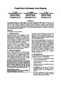
limited bit width. The independent exponents act as a correction to the block exponent shared by all elements of the array. Allowing limited independence in exponents provides added flexibility in implementation. Note that both of the aforementioned approaches leverage special instructions provided by specific processors. All BFP implementations discussed so far require that shifts and scales be hand-crafted. While this allows one to take advantage of the intricacies of specific algorithms and processors, the approach is time-consuming and prone to subtle errors. In contrast, our approach is a general methodology for implementing a wide variety of signal processing algorithms using BFP arithmetic. We automate scaling in BFP arrays for operations that can be expressed as a combination of any number of additions and multiplications. General algebraic expressions, and operations such as convolution, are decomposed into these elementary operations using dataflow graphs. In an analysis step, the shifts and scales are calculated for each addition or multiplication operation based on the dynamic range of the input arrays. Analysis results for each elementary operation are accounted for in the analysis of the next operation in the graph. Our use of dataflow graphs for decomposing expressions is similar to that suggested for scalars in fixed-point arithmetic [10]. This analysis is performed once for the entire graph followed by the actual operation loop over the elements of the BFP arrays. The main advantage of our approach is its generality. It can be realized as a C or C++ library that automates the analysis and eliminates the need to hand-craft scaling for every BFP operation. 3. OUR APPROACH We begin by describing a framework for applying BFP arithmetic to elementary two-operand array operations: addition and element-wise multiplication. Then we show how this framework can be extended to composite multi-operand expressions involving BFP arrays. 3.1. The Elementary BFP Operation An elementary BFP operation consists of two steps (Fig. 1): • The Analysis: A two-operand expression is analyzed to determine the appropriate shifts of the operands, the shift for the intermediate result, and the scale of the final result. • The Operation Loop: Computes the mantissas of the final result using the shifts determined in the Analysis step to prevent overflow and preserve accuracy. For any BFP array A, let Ascale denote the scale of A, Amax denote the maximum value of A, and Ashif t denote the shift that must be applied to an element of A to prevent
A, B
Amax, Ascale, Bmax, Bscale
Analysis
Cscale
Ashift, Bshift, Ishift
Operation Loop over array’s elements
C
Fig. 1. The structure of an elementary operation C = f (A, B), where A, B, and C are BFP arrays. The Analysis step calculates the shifts for the operands, the right-shift for the intermediate result and the final result’s scale. The Operation Loop performs the actual operation on the elements of the arrays, using the shifts calculated in the Analysis step.
overflow during a given operation. Let C = f (A, B) be an elementary operation, where A, B, and C are BFP arrays. When f is applied to the corresponding elements of A and B, the result is first stored in an accumulator variable. The word-length of the accumulator is typically greater than that of A, B and C to preserve accuracy. Let I be this intermediate result stored in an accumulator variable. Let Imax be the upper bound on the value of the mantissa of I. Let Iscale be its scale and Ishif t be the number of bits by which I needs to be right-shifted to fit into an element of C. Thus, the input parameters for the Analysis step are Amax , Ascale , Bmax and Bscale . The outputs are Ashif t , Bshif t , Ishif t and Cscale . The values of Ashif t , Bshif t and Ishif t are used in the Operation Loop while Cscale is applied to the result. The Analysis itself consists of two phases (Fig. 2). The first phase, the major phase, calculates Ashif t and Bshif t , and also Imax and Iscale for the specific operation. The details of how the shifts are determined for element-wise multiplication and addition are given in Sections 3.1.1 and 3.1.2 respectively. The second phase, the minor phase, uses Imax and Iscale to calculate Ishif t and Cscale as follows. Let Ib be the number of bits spanned by Imax . Let Csize be the word-length of C. If Ib < Csize , then the maximum value of the intermediate result fits into C and Ishif t = 0. Otherwise, Ishif t = Ib − Csize . Once we know Ishif t , then Cscale = Iscale + Ishif t . Note that the word-lengths of the arrays and the accumulator are assumed to be known a priori. The minor phase of the Analysis step is distinguished from the major phase to facilitate multi-operand analysis. Specifically, Imax and Iscale are propagated as inputs into the analysis of the next elementary operation in the dataflow
graph (Section 3.2). In the following two sections we discuss the details of determining shifts for the operands in the first phase of the Analysis step. One may calculate all necessary shift values based on the maximum value computed using interval arithmetic. For example, the result of adding A and B has a maximum value of Amax + Bmax . In computing the maximum, we choose to implement a slightly different approach. Our approach is based on the maximum number of bits spanned by Amax and Bmax rather than their sum. This approach results in a looser bound than the interval arithmetic approach. The looser bound might lead us to incorrectly predict overflow, resulting in unnecessary shifts of an operand. However, this approach lends itself to easier analysis and is a very close approximation to interval arithmetic. The following sections explain this analysis in greater details. Amax, Ascale, Bmax, Bscale
2. Right-shift Amax until it spans as many bits as Bmax or until the the sum of the number of bits spanned by them is equal to the word-length of the accumulator. 3. Right-shift Amax and Bmax by the same amount so that the sum of the number of bits spanned by them is equal to the word-length of the accumulator. 3.1.2. Determining Shifts For Addition When adding two unsigned numbers, two constraints need to be satisfied: 1) each operand’s mantissa must span at most one less bit than the word-length of the accumulator, and 2) the exponents of the operands must be equal. Similar logic also applies to signed numbers, but the negative extremum needs to be taken into account. Since accuracy is lost by rightshifting, it is preferable to use left-shifting whenever possible to equalize the operands’ exponents. Thus, the shifts for addition of BFP arrays A and B are determined as follows: 1. Assume without loss of generality that Ascale ≥ Bscale .
Major Phase : Operands
Imax, Iscale
Minor Phase : Result
Ashift, Bshift
Ishift, Cscale
Fig. 2. The Analysis Step of an elementary BFP operation C = f (A, B) consists of two phases. The first calculates the shifts of the operands, and the second calculates the right-shift for the intermediate result the scale of the output C. 3.1.1. Determining Shifts For Element-wise Multiplication Preventing overflow during multiplication requires one to ensure that the sum of the number of bits spanned by the mantissa of each operand does not exceed the word-length of the accumulator variable. If this condition is violated, the operands’ mantissas must be right-shifted and their exponents updated accordingly. When a right shift is required for both operands, it can be shown that the worst case accuracy is maximized when the mantissas of the two operands span an equal number of bits1 . Therefore, the shifts for the elementwise multiplication of BFP arrays A and B are determined as follows (note that right shifting is required only if the accumulator’s word length is exceeded): 1. Assume without loss of generality that Amax spans more bits than Bmax . 1 This approximately holds when the bounds on the mantissas of the arrays are much greater than one. The proof is omitted in the interest of brevity.
2. Left-shift Amax as much as possible until either the exponents are equalized, or Amax spans one bit less than the word-length of the accumulator. 3. If the exponent of A is still greater than that of B, rightshift Bmax to equalize the exponents. 3.1.3. The Operation Loop The operation loop executes the element-wise multiplication or addition of two BFP arrays. The heart of the loop is over the elements of the two operands A and B (ai and bi ) and consists of the following steps: 1. Assign elements ai and bi to temporary accumulator variables a0i and b0i respectively 2. Shift a0i and b0i by Ashif t and Bshif t respectively 3. Perform the operation on the shifted elements a0i and b0i and assign the result to the intermediate variable I 4. Right-shift the intermediate result by Ishif t 5. Assign the final result to ci The output BFP array C has corresponding scale Cscale as computed in the second phase of the Analysis step. While multiplication operations only require right shifts, addition operations could require both right and left shifts. In the discussion so far, we have assumed the availability of negative right shifts (implied left shift), which is unlikely to be supported by the compiler. While a conditional statement that interprets the negative shifts fixes the problem, it creates a significant performance overhead. Moreover, in the case of multi-operand BFP arithmetic, the number of conditional statements increases exponentially with the number of operands. We propose a better solution:
1. For any shift Ashif t , computed during the analysis step, we compute both a left shift (Alef t-shif t ) and a right shift (Aright-shif t ). If Ashif t is positive, then Aright-shif t = Ashif t and Alef t-shif t = 0. On the other hand, if Ashif t is negative, then Aright-shif t = 0 and Alef t-shif t = −Ashif t . 2. In an operation loop involving addition, both the right (Aright-shif t ) and the left shift (Alef t-shif t ) are applied. Many DSPs (including the TI C64x used in our application) support intrinsics that perform both a left and a right shift in a single cycle. Thus, the additional complexity imposed by the application of two shift instructions on the same variable is negated. 3.2. Multi-Operand BFP Arithmetic: Combining Elementary Operations Section 3.1 presents the notion of an elementary operation involving two BFP operands. While two-operand BFP arithmetic has been used in various forms in the literature, the framework presented in the previous section enables the main contribution of our work: applying BFP arithmetic to composite algebraic operations on arrays. To that end, we begin by showing how an algebraic expression can be decomposed into a sequence of elementary operations. Then, we show how the Analysis step for one elementary BFP operation can be extended to a sequence of such operations. Any algebraic operation can be represented as a dataflow graph, wherein each node corresponds to an addition or a multiplication operation [10]. The graph is structured such that the output of one operation (a node in the graph) becomes the input to the next. For example, the dataflow graph for the expression F = (A+B)◦D, where ◦ denotes the Hadamard (i.e, element-wise) product of two vectors, is shown in Fig. 3(a). The Analysis step for this expression is shown in Fig. 4. In general, the Analysis step for a multi-operand algebraic operation consists of a sequential application of the major analysis phase (Section 3.1), followed by a single application of the minor analysis phase. Each sequential application of the major analysis phase corresponds to a node in the graph and its order in the sequence is also dictated by the graph. The operand’s shifts computed by each application of the major analysis phase are used in the Operation Loop, and the intermediate result’s maximum and scale are fed into the major analysis phase of the next elementary operation in the graph. Finally, a single application of the minor analysis phase is needed to compute the shift of the final accumulator and the scale of the resulting BFP array. The computed set of shifts for each elementary operation and the result are then applied to elements of the BFP array in the operation loop as before (Section 3.1.3). The operation loop evaluates the expression and outputs the BFP array F .
ai
ai
bi
ai+1
×
di
+
kn
kn-1
k1 ×
× +
×
a.
ai+n-1
+
b.
Fig. 3. a: Dataflow graph for composite operation F = (A + B) ◦ D. b: Dataflow graph for a convolution A ∗ K with a kernel of n elements. While we have found the multi-operand approach suggested in this section to be quite effective for expressions of moderate length, the impact of sequential analysis on accuracy deserves some attention. Specifically, note that the estimated bounds on the intermediate results propagated sequentially through the analysis for each elementary operation get increasingly looser. This is an inherent limitation of interval arithmetic, and it results in a loss of accuracy. Thus, for an expression with a large number of elementary operations, such as multiplication of large matrices, this loss of accuracy should be carefully considered. If the number of elementary operation is so large that the loss of accuracy is unacceptable, it is possible to break up the original composite BFP operation into a series of smaller sub-operations. Each sub-operation is itself a composite BFP operation with its own Analysis step and Operation Loop. To prevent the loss of accuracy the actual maximum of the result of each sub-operation needs to be determined in its Operation Loop to be used as input to the Analysis step of the next suboperation. This incurs an additional computational cost, but when accuracy is paramount performing this correction is an effective remedy. 3.2.1. Convolution Convolution represents a non-trivial, yet common, application of our approach. It clarifies certain design and implementation considerations not explicitly stated in the prior sections. We follow this section with an evaluation of our approach that is based on convolution. Consider convolving an array A with a kernel K, where both are BFP arrays. Let n denote the number of elements in K. The dataflow graph for one step (a single dot product) of the convolution A ∗ K is shown in Fig. 3(b) 2 . As before, the shifts for the operands at each node in the dataflow graph must be determined in the analysis step. However, in this case, the operands are elements of the same BFP arrays. In other words, operand pairs (ai , kn ) and (ai+n−1 , k1 ) in Fig. 3(b) come from the same BFP arrays A and K. This 2 Note that the dataflow graph represents a dot product of two arrays. Thus, the approach suggested in this section can be similarly extended to matrix multiplication.
Amax, Ascale
Bmax, Bscale
Dmax, Dscale
Analysis. Major Phase for I1 = A + B
Ashift, Bshift
I1max, I1scale
Analysis. Major Phase for I2 = I1 ○ D
I1shift, Dshift
I2max, I2scale
Analysis. Minor Phase
I2shift
Fscale
Operation Loop
F
Fig. 4. The structure of a composite operation F = (A + B) ◦ D, where A, B, D, and F are BFP arrays. The major phase of the Analysis step is performed once for each elementary operation, and the output of the major Analysis phase of one operation becomes the input for the major Analysis phase of the next operation. Only one minor Analysis phase is needed for the entire composite operation.
implies that the analysis for the entire dataflow graph can be efficiently implemented as a loop over the n elements of the kernel K. Within the loop, the analysis is performed for multiplication of an operand pair (e. g. (ai+2 , kn−2 )) and its addition with the intermediate result (the accumulated sum ai × kn + ai+1 × kn−1 ). As before, the calculated bound on the intermediate result at each iteration becomes the input for the analysis performed in the next iteration. The operand’s shifts calculated in each iteration are stored in arrays of length n. Note that if the kernel size n changes, the structure of the analysis does not change. Even runtime changes in kernel size can easily be accommodated. The Operation Loop iterates over the elements of A. Each step of the convolution is implemented as an inner loop over the n elements of K. Each inner loop iteration uses the shifts calculated by the corresponding iteration in the Analysis. 4. EVALUATION We evaluate the performance of our approach in terms of its accuracy and speed by implementing a steerable filter [11] . We compute the directional responses dx and dy of a grayscale image by convolving it with two steerable 5 × 5
orthogonal basis kernels. The kernels and the input image are stored in a 16-bit BFP array. The results are stored in 32-bit BFP arrays. Each convolution step (i. e. the dataflow graph) consists of 25 multiplications and 24 additions for which 32-bit accumulators are used. We steer the filter responses dx and dy to determine the responses at eight discrete directions for each pixel. We refer to the dominant response across the eight directions as the orientation index for each pixel. Note that some loss of accuracy during convolution might not result in an incorrect orientation index. First, we evaluate the accuracy of our BFP implementation. Let A denote the input image. Ideally, Amax is set to the actual maximum mantissa µ of the BFP array A. However, this is possible only if µ is known in advance or is determined by examining every element of A. In practice, we avoid the cost of determining µ and set Amax to be the largest value that fits into the world-length of A. Thus, Amax is likely an overestimate, which results in a loss of accuracy. To characterize how an overestimate of Amax affects the accuracy of this particular BFP operation, we test it on a set of randomly generated images with varying dynamic range. In our experiment, Amax is set to 216 − 1. The pixel values of the test images are uniformly distributed between 0 and µ = 2n −1, where n ≤ 16 is the number of bits spanned by µ. The total number of pixels in the test images for each value of n is 3.4 × 10⁶ . The results obtained using BFP arithmetic are compared with the corresponding floating-point results. The error � for each pixel is calculated as the absolute difference between the BFP and floating-point results, normalized by the average absolute value of the floating-point result. The error � averaged over all pixels as a function of n is shown in Fig. 5. The error bars correspond to one standard deviation of �. The observed distribution of error is attributable to two sources: 1) the loss of accuracy caused by the shifts and, 2) the round-off error related to the word-length of the accumulators. In this case, the entire chain of the elementary operations can be performed without any shifts when using 64-bit accumulators. Thus, using 64-bit accumulators, we can estimate the error attributable to round-off. We find that � approaches the round-off error as n approaches 16. Thus, the discrepancy between the floating-point and the BFP results for n > 8 is largely accounted for by the round-off error. We can establish an objective criterion for acceptable accuracy based on the correctness of the final result: the orientation indices. We define the orientation index error to be the fraction of pixels in the image wherein the BFP result differs from its floating-point counterpart. As before, the two sources of error are shifts and round-off. The orientation index error caused by round-off is 0.005%. We have determined empirically that orientation index error of less than 1% has no effect on the overall performance of our application (object recognition). The orientation index error caused by the shifts for n = 4 is 0.162%. Thus, even a gross overestimate of Amax
leads to acceptable accuracy. Finally, we also evaluate the time overhead of performing the Analysis step. To determine this overhead, we measure the execution time for the Analysis step and the Operation Loop for calculating the dx and dy components of the steerable filter on a TMS320DM6437 DSP. The execution time for the Analysis step is 40 microseconds while the mean execution time for the Operation Loop is 0.6 microseconds per pixel. Thus, assuming that the acceptable overhead for the Analysis step is less than 1%, our approach is applicable to arrays larger than 7 × 10³ elements, which corresponds to images larger than 100 × 70 pixels. In practice, the same composite BFP operation is often executed in a loop and analysis step is identical for each execution. In such situations, the Analysis step only needs to be performed once for the entire loop, making the overhead negligible. x 10
Normalized Mean Absolute Error
1.8 1.6
[1] M. Saptharishi, Sequential Discriminant Error Minimization: The Theory and Its Application to Real-time Video Object Recognition, Ph.D. thesis, Carnegie Mellon University, Pittsburgh, PA, 2005. [2] A. Oppenheim, “Realization of digital filters using block-floating-point arithmetic,” IEEE Trans. on Audio and Electroacoustics, vol. 18, pp. 130 – 136, June 1970.
[4] A. Mitra and M. Chakraborty, “A block-floating-point treatment to the LMS algorithms: Efficient realization and a roundoff error analysis,” IEEE Trans. on Signal Processing, vol. 53, no. 12, pp. 4536 – 4544, 2005.
1.4 1.2 1 0.8
[5] H. Ochi, “RTL design of parallel FFT with block floating point arithmetic,” in IEEE Conf. on Soft Computing in Industrial Application, 2008, pp. 273–276.
0.6 0.4 0.2 0
6. REFERENCES
[3] K. Kallioj¨arvi and J. Astola, “Roundoff error in blockfloating-point systems,” IEEE Transactions on Signal Processing, vol. 44, no. 4, pp. 783 – 790, April 1996.
−3
2
Our method can be implemented as a C or C++ library that abstracts the analysis for many common algebraic expressions and elementary operations. Additionally, the implementation is largely processor independent. Thus, development complexity can be greatly reduced while ensuring that the implementation is efficient, reliable and maintainable.
4
6
8 10 12 Dynamic Range in Bits
14
16
Fig. 5. Normalized mean absolute error � of a BFP steerable filter as a function of the actual dynamic range of input A in bits. The upper bound Amax used in the analysis was 216 − 1.
5. CONCLUSIONS We have proposed a novel approach for extending block floating-point arithmetic to multi-operand algebraic expressions. The approach includes a general methodology for automatically calculating binary shifts for the operands and the intermediate results at run-time. The developer need not hand-craft a BFP implementation for every specific operation. This approach applies to many array operations common in image processing. It also has the advantage of not requiring design-time empirical range estimation of the data. This advantage comes at a cost when considering long algebraic expressions (see Section 3.2) and also when estimates of Amax deviate significantly from the actual. Both of these costs can be reduced by increasing the computational complexity of the analysis and the operation loop. The tradeoff between computational cost and accuracy depends on the application and has to be considered carefully.
[6] M. Chakraborty, R. Shaik, and M. H. Lee, “A blockfloating-point-based realization of the block LMS algorithm,” IEEE Trans. on Circuits and Systems II: Express Briefs, vol. 53, pp. 812 – 816, September 2006. [7] K. Ralev and P. Bauer, “Implementation options for block floating point digital filters,” in Proc. IEEE Int. Conf. on Acoustics, Speech, and Signal Processing, 1997, vol. 3, pp. 2197 – 2200. [8] D. Elam and C. Iovescu, “A block floating point implementation for n-point FFT on the TMS320C55x DSP,” Tech. Rep., Texas Instruments, September 2003. [9] S. Kobayashi and G. Fettweis, “A new approach for block-point arithemetic,” in Proc. of Int. Conf. on Acoustics, Speech, and Signal Processing, March 1999, vol. 4, pp. 2009 – 2012. [10] M. Willems, M. B¨ursgens, H. Keding, T. Gr¨otker, and H. Meyr, “System level fixed-point design based on an interpolative approach,” in Proc. of the 34th Design Automation Conf. IEEE, 1997, pp. 293 – 298. [11] W. Freeman and E. Adelson, “The design and use of steerable filters,” IEEE Trans. on Pattern Analysis and Machine Intelligence, vol. 13, pp. 891 – 906, 1991.