internal mailing lists for MBT would count only about 5-10% of product teams ..... Test Management Test automation does not end with the generation of test ...
Multi-Paradigmatic Model-Based Testing Wolfgang Grieskamp August 2006 Technical Report MSR-TR-2006-111
For half a decade model-based testing has been applied at Microsoft in the internal development process. Though a success story compared to other formal quality assurance approaches like verification, a break-through of the technology on a broader scale is not in sight. What are the obstacles? Some lessons can be learned from the past and will be discussed. An approach to MBT is described which is based on multi-paradigmatic modeling, which gives users the freedom to choose among programmatic and diagrammatic notations, as well as state-based and scenario-based (interaction-based) styles, reflecting the different concerns in the process. The diverse model styles can be combined by model composition in order to achieve an integrated and collaborative model-based testing process. The approach is realized in the successor of Microsoft Research’s MBT tool Spec Explorer, and has a formal foundation in the framework of action machines. Microsoft Research Microsoft Corporation One Microsoft Way Redmond, WA 98052 http://www.research.microsoft.com
1
Introduction
Testing is one of the most cost-intensive activities in the industrial software development process. Yet, not only is current testing practice laborious and expensive but often also unsystematic, lacking engineering methodology and discipline, and adequate tool support. Model-based testing (MBT) is one of the most promising approaches to address these problems. At Microsoft, MBT technology has been applied in the production cycle since 1999 [1–5]. One key for the relative success of MBT at Microsoft is its attraction for a certain class of well-educated, ambitious test engineers, to which it is one way to raise testing to a systematic engineering discipline. However, at the larger picture, an estimate based on the number of subscriptions to internal mailing lists for MBT would count only about 5-10% of product teams which are using or have tried using MBT for their daily tasks. While these numbers can be considered a success compared to other formal quality assurance approaches like verification, they are certainly not indicating a break-through. So what are the obstacles in applying MBT, and how can a larger group of users be attracted to the technology? This paper first makes an attempt to answer this question, based on feedback from the user base of the Spec Explorer tool [5], its predecessor AsmL-T [3], and other internal MBT tools at Microsoft. The major issues, apart of the ubiquitous problem in the industry that people do not have enough time to try out new technology and educate themselves, seem to be the steep learning curve for modeling notations together with the lack of state-of-the-art authoring environments, missing support for scenario-based (interaction-based) modeling, thus involving not only the test organization but also other stakeholders in the process, poor documentation of the MBT tools, and last but not least technical problems like dealing with state explosion, fine-grained test selection, and integration with test management tools. The paper then sketches a new model-based testing environment which is currently under development at Microsoft Research and attempts to overcome some of the obstacles. The environment, called “Spec Explorer for Visual Studio” (for short, SEVS ), tries to address the identified challenges by providing a full integration into the development environment of Visual Studio, using a multi-paradigmatic approach to modeling, allowing to describe models on different levels of abstraction, using scenario and state oriented paradigms as well as diagrammatic and programmatic notations, and enabling the combination of those diverse artifacts for a given modeling and testing problem. SEVS is internally based on the framework of action machines [6, 7], which allows for uniform encoding of models which can stem from a variety of notations, and to combine and relate them using various compositions. The action machine framework supports the representation of models with symbolic parts in states and actions, which gives rise to the expressive power of defining partial models on a higher level of abstraction and compose them with lower-level models. This paper is organized as follows. Sect. 2 describes lessons learned in applying MBT at Microsoft and draws some conclusions. Sect. 3 gives a high-level overview on the approach of the SEVS tool using examples. Sect. 4 gives a summary of the formalization of the underlying concepts, and Sect. 5 concludes. 1
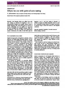
class Publisher { Set subscribers = Set{}; [Action(ActionKind.Controllable)] Publisher(){} [Action(ActionKind.Controllable)] void Publish(object data) { foreach (Subscriber sub in subscribers) sub.mbox += Seq{data}; } }
class Subscriber { Seq mbox = Seq{}; [Action(ActionKind.Controllable)] Subscriber(Publisher publisher) { publisher.subscribers += Set{this}; } [Action(ActionKind.Observable)] void Handle(object data) requires mbox.Count > 0 && mbox.Head.Equals(data); { mbox = mbox.Tail; } }
Fig. 1. Publisher-Subscriber Model
2
Model-Based Testing in Practice: Lessons Learned
MBT has a long application tradition at Microsoft, and various tools have been and are in use. The first tool, the Test Modeling Toolkit (TMT), was deployed in 1999, and is based on extended finite state machines (EFSM) [1]. Microsoft Research deployed two tools, AsmL-T in 2002 [3] and Spec Explorer in 2004 [5], both using executable specification languages based on the the abstract state machine paradigm (ASM) [8] as the modeling notation. Other internal tools which have not been published are also around. The general mailing alias used for internal discussion of MBT issues at Microsoft currently exceeds 700 members. All these tools, though quite different in details and expressiveness, share some common principles. Models are described by guarded-update rules on a global data state. The rules describe transition between data states and are labeled with actions which correspond to invocations of methods in a test harness or in the actual systemunder-test (SUT). Rules can be parameterized (and the parameters then usually also occur in the action labels). A user provides value domains for the parameters, using techniques like pairwise combination or partitioning. In the approach as realized by AsmL-T and Spec Explorer, the parameter domains are defined by expressions over the model state, such that for example they can enumerate the dynamically created instances of an object type in the state where the rule is applied. A very simple example to demonstrate the basic concepts as they appear in Spec Explorer today is considered. The model describes the publish-subscribe design pattern 2
which is commonly used in object-oriented software systems. According to this pattern, various subscriber objects are registered with a publisher object to receive asynchronous notification callbacks when information is published via the publisher object (in fact, the subscribers can dynamically register and unregister at a publisher, but this aspect is simplified here.) Thus this example includes dynamic object creation as well as reactive behavior. The model is given in Fig. 1 (top). The state of the model consists of publisher and subscriber instances. A publisher has a field containing the set of registered subscribers, and a subscriber has a field representing the sequence of data it has received but not yet handled (its “mailbox”). The model simply describes how data is published by delivering it to the mailboxes of subscribers, and how it is consumed by a subscriber in the order it was published. The precondition of the handling method of the subscriber enables it only if the mailbox is not empty, and if the data parameter equals to the first value in the mailbox. Note that the Handle method is an observable action, which comes out as spontaneous output from the system under test (SUT). Fig 1 (bottom) shows an excerpt from the state graph generated by Spec Explorer from this model. This kind of graph corresponds to an interface automaton [9]. In this fragment, one publisher and two subscribers are configured (the state graph omits the configuration phase). From state S3, a Publish invocation is fired, leading to state S4, which is an observation state where the outgoing transitions are observable actions. The meaning of an observation state is that the SUT has an internal choice to do one of the outgoing transitions, as opposed to a control state (S3) where it must accept all of the outgoing transitions. Thus, effectively, the model gives freedom to an implementation to process the subscribers of a publisher in any given order. In order to generate the state graph, the model was augmented with further information: the parameters passed to the Publish method have been specified (here, "foo"), the number of publishers and subscribers to be created has been bounded, as well as the number of messages in the mailbox of a subscriber. Such state graphs are then input to traversal algorithms to generate a test suite which can be executed offline, or are dynamically traversed using online/on-the-fly testing. For both cases, the test execution environment takes care of binding object values in the model to objects in the implementation, as well as queuing asynchronous observable action invocation events in the SUT for consumption by the model. For details, see [5]. In practice, models written with Spec Explorer are significantly larger than this simple example; yet they are rarely on the scale of real programs. In the applications at Microsoft, models typically introduce about 10 to 30 actions, with up to 2000 lines of model code, in exceptions over 10000 lines. Yet, these models are able to test features with a code-base which is larger by an order of magnitude or more. This stems from the level of abstraction chosen in modeling. Model-based testing is used for a wide range of application types, including user interfaces, protocols, windows core components, frameworks, device drivers, and hardware abstraction layers. While in general successfully used in practice, the technology of Spec Explorer, as well of the other available tools at Microsoft, raises some challenges which hinder wider adoption. These will be discussed in the remainder of this section. 3
2.1
The Modeling Problem
Authoring Computer folklore says: “every editor is better than a new editor”. Though clearly this statement is sarcastic, one should not underestimate its wisdom. The author of this paper, for example, used to apply the vi editor (a great relict of very early Unix times) for his programming over many years, even though on the development platform Visual Studio was available, which provides automatic indentation, incremental compilation, context-sensitive completion, refactoring, and many more nice features. When initially rolling out one approaches’ favorite modeling notation to end users, the gravity of habits is even stronger: users are asked to use a new language in an authoring environment which usually does not provide the convenience features they are acquainted with from modern environments. Notations have perhaps become less important today than the environments which support them. This at least applies to users which are heavily using these modern development environments – among which are most younger testers and developers. It might apply less to other stakeholders (like the author of this text, which is still using a vi emulation mode under Emacs to write this document in LATEX). The lesson learned is that if one comes up with a new notation, one should better be sure that either the users of that notation do not care about modern authoring support, or one should match this support. The later is unfortunately not trivial. The effort for decent authoring support for a language is probably an order of magnitude higher than providing its compiler. Executable Specifications vs Programming Languages The first generation of the Microsoft Research MBT tools was based on the Abstract State Machine Language (AsmL), a high-level executable specification language, which integrates concepts from functional programming languages and specification languages like Z, B and VDM. Though the basic concepts of this language seem to be simple and intuitive (it uses a “pseudo-code” style notation and avoids any mathematical symbols), apart of some stellar exceptions, for most testers the learning curve was too steep (see [4] for a discussion). Testers struggled with concepts like universal and existential quantification and set comprehensions. Under the assumption that the problem was not the concept itself but perhaps the unfamiliar way in which it was presented, the next generation, Spec Explorer, offered in addition to AsmL the Spec# notation, which disguised the high-level concepts in C# concrete syntax. Though this approach was more successful, the basic problems remained. Typically, beginners and even intermediate levels in Spec# prefer to write a loop where a comprehension would be much more natural and concise. This phenomena is not just explained by the inability of users. It is more the unwillingness to learn many new concepts at the same time, in particular if they are not obviously coherent. Confronted with a new technology like MBT and the challenges to understand the difference between model and implementation and finding the right abstraction levels, having in addition the challenge to learn a new language, is mastered only by a minority. Some people argue that a high-level notation which differs from the programming notations might support identifying different levels of abstractions, as they are essential 4
for modeling. The AsmL and Spec# experiences do not confirm this, at least in the beginning of the adoption process. Rather, it seems that if the notation is mastered after some time, a misleading conceptualization takes place: abstraction is identified with notation, which after all is only syntactic sugar (in the case of executable specification languages). Someone who already masters the abstraction process will certainly benefit from a more concise way to write things down. But for others, the notation can be just a further roadblock in mastering the technology. The conceptual distance between programming languages like C# and executable specification languages like Spec# is shrinking steadily. The new forthcoming C# version 3.0 will contain – in addition to the relatively declarative notational features C# has already now – support for comprehension notations (as part of the LINQ project [10]). When new language concepts are build into main-stream programming languages like C# or Java, a campaign is kicked off. Manufactures provide early technology previews, blogs and message boards are filled, books are written or newly edited, and so on. After some time, the concepts which might have appeared strange to the average programmer are familiar to many. Why trying to compete with this? The lesson learned here is that it appears wiser not to mix evangelizing executable specification languages with the very core of model-based testing concepts. This should not mean that those notations do not have a place in MBT – they are indeed rather important. It just means that users should not be forced to use a new notation and environment in order to write their first models. Let them use existing programming notations and their authoring environments if they like. The core of a model-based testing approach and tool should be agnostic about this choice; it should be multi-paradigmatic. Scaling up to Model-Based Development One of the promises of MBT is to be an entry door for model-based development. In course of applying MBT at Microsoft, several test teams have attempted to incorporate program managers, domain experts, business analysts, and the like into the modeling process. This has not been very successful so far, though some exceptions exist. One interesting observation is that executable specification languages like AsmL, which provide a high-level pseudo-code style notation, are more attractive to those stakeholders than programming-oriented notations like Spec#. AsmL had more users authoring system models, compared to just models for test, whereas with the introduction of Spec# and Spec Explorer, these applications diminished. This is a strong argument to continue supporting high-level executable specification languages like AsmL for MBT (just do not make them the only choice). However, it seems that the main obstacle here is not the language but the modeling style. AsmL, Spec#, or any of the other MBT approaches used at Microsoft are not attractive in the requirements phase since they are state-based instead of scenariobased. In this way they represent a design by itself – even if on an higher-level of abstraction. These high-level designs are well suited for analysis, but less well for understanding and communicating usage scenarios. Thus to incorporate stakeholders from the requirements league, scenario-based modeling must be supported. Scenarios are also heavily used inside of the test organizations themselves. For example, test plans are commonly used at Microsoft to describe (in an informal way) what usage scenarios of a feature should be tested. These test plans, as well as the scenarios 5
coming from the requirements phase, are intrinsically partial, omitting a lot of details, in particular oracles, parameter assignments, and so on. It is the job of the test engineers to “implement” these test plans. The challenge for MBT to scale up to model-based development is the support of both the state-based and the scenario-based paradigm in one approach, where it is possible to combine (compose) models coming from those different sources. For example, a scenario might provide the control flow, and a state machine the oracle, and the composition of both produces an instantiated test suite. How should scenario-based models be written down? In [11], a programmatic approach based on Spec# is suggested. While this approach is useful in some instances, diagrammatic approaches like activity charts or interaction charts look more promising, as far as stakeholders from the requirements phase should be involved. Because of the wealth of literature available, it seems wise to orient toward UML 2.0 when supporting diagrammatic notations, instead of inventing ones own. But again, the choice of the notation should not be part of the core of an MBT approach and tool. Education and Documentation For more than a decade, proponents of formal methods claim that the major problem in adoption is education. In particular universities are in charge of providing better preparation for those technologies. However, as long as there are no practical applications and tools around, only a minority of students will subscribe to this content. Until then, the adoption problem must be solved in the field. To that end management support is the essence. At Microsoft, the most successful applications of MBT emerged in areas where the technology was pushed from management level by making time resources available for the adoption phase. This has to go in combination with introduction classes and seminars, and – most important – good documentation and samples. See [4] for a discussion. 2.2
The Technology Problems
State Explosion MBT is known to easily generate a huge amount of tests from even small models. But this turns out to be more a problem in practice than an advantage, commonly referred to as the “state explosion problem”. In fact, this is the main concern mentioned by users of MBT tools at Microsoft. The state explosion problem has a number of facets. First, the time required to run a test-suite is a significant cost factor. For example, at Microsoft, developers need to run so-called “basic verification tests” (BVT) before they can submit sources to a shared depot. The time required to run the BVT is important for development productivity. If BVTs require hours to finish, developers tend to submit their changes in larger time intervals, which raises problems with the integration of their changes with other developers changes. This is also a reason why stochastic on-the-fly/online testing is not the solution for the state explosion problem. It is not realistic to run millions of tests “over night” in the standard development process. Indeed, this kind of testing has its proper use in test deployments which run in test labs asynchronously with the development process and in larger time intervals. 6
Test Selection The notion of test selection is generally used in the MBT community to name the process of selecting some representative set of tests from the model. Thus it should provide the tools to overcome the state explosion problem. Test selection traditionally covers graph traversal techniques which can be applied to models which are boiled down to some finite state machine representation, as well as techniques for generating parameters of tested actions, like pairwise combination, partitioning, and so on. In the context of models which have an unbounded state space, like Spec Explorer models, test selection can also include bounds, filters, state grouping, and other techniques to prune the state space. While these techniques are mostly automated and well understood, it is a regular complain of MBT users at Microsoft that they have not enough fine-grained control over the test selection process. For example, a typical user problem is to choose the set of tests from the model where during some initialization phase an arbitrary path is sufficient, in the operation phase paths should be chosen such that all transitions are covered, and in the shutdown phase again an arbitrary path is good enough. MBT tools need to support this kind of fine-grained control over the test selection process. Some tools support defining so-called test purposes which are combined with the model to slice some desired behavior, using special notations for that [12, 13]. Instead of introducing a further notation for describing test purposes, it looks desirable to use models to express test purposes and view the test selection problem with test purposes as a model composition problem. Test purposes then fall together with test plans and requirement scenarios, as discussed previously. Even more than for those applications, models used as test purposes must allow to express partial behavior which omits many details. Model Analysis Another facet of the state explosion problem is the understanding of what the model actually does. Since models represent human abstractions they can be error-prone in missing some intended behaviors because of over-abstraction. Therefore, they require “debugging”. Debugging a model for MBT effectively means exploring and analyzing the state space it spans, both by humans and automatically. The Spec Explorer tool invests a great lot of detail to support human analysis by its viewing capabilities, which allow to visualize the state space directly or using projection techniques. These capabilities are one major cornerstone for the success of the tool, and need to be maintained and extended. The Spec Explorer tool also supports model-checking with safety and liveness properties. However, this support is not very well developed in comparison to decent modelchecking tools, and temporal property checking is not available. Model checking is a key feature that makes modeling more attractive for stakeholders outside of the test organization. Consequently, user requests for supporting model-checking in model-based testing tools come from this side. Test Management Test automation does not end with the generation of test cases. In particular, if it comes to testing of distributed systems and/or testing of software on heterogeneous hardware, test management is a significant effort of the overall process. At Microsoft, a variety of test management tools are in use which allow distribution of test jobs on matching hardware and execution of orchestrated tests inclusive of log7
ging for collecting the test results. Other tools support measuring coverage of test suites. The integration of this set of tools with model-based testing tools is only marginally developed, and an improvement here is an often requested feature. For example, users want end-to-end tracking of test case execution with the model source, test versioning, automatic bug filing, generation of repros for failed test runs, and so on. Visual Studio Team Suite 2005 added support for test management, as well as for unit testing. It is desirable to leverage this support for an MBT solution integrated into Visual Studio. However, experiences show that requirements and tools for test management often differ from product unit to product unit. Thus a unified, single solution for test management might not be adequate. Therefore, the best strategy for an MBT tool seems be to have a well-defined abstraction layer over the test management support, which allows deployment of different tools underneath – very similar like development environments do today for source control and versioning. The definition of this layer is an open problem.
3
A Multi-Paradigmatic Approach and Tool
Over the past year, Microsoft Research has developed a new tool for modeling and model-based testing, called “Spec Explorer for Visual Studio” (for short SEVS ), which strikes out to meet some of the challenges learned from the experiences with older tool generations. This tool provides a full integration of model-based testing and modelchecking in the Visual Studio environment on base of a multi-paradigmatic approach to modeling as motivated in the previous section. In its intended final stage of expansion, models can be written in SEVS using any .NET language (including AsmL), supporting whatever authoring environment is available for a given language. The tool also provides the use of UML 2.0 behavior diagrams, which are realized using Visual Studio’s domain specific language support [14]. Models can be either state-based or scenario-based, in both textual and diagrammatic flavors. A central feature of SEVS is the ability to compose models stemming from different paradigms. For example, a scenario-based model (given in any notation) can be put in parallel composition with a state-based model (given in any notation), producing the combined behavior of both. As discussed in the previous section, the scenario model could e.g. be a test plan which describes a control flow on a high abstraction level, whereas the state-based model could represent the “implementation” of the omitted details of the test plan (and other test plans in the same domain). Besides parallel composition, the tool supports various other compositions (for a complete description see [7]). SEVS is based on the semantic and implementation framework of action machines [6]. The action machine framework supports the representation of models with symbolic, “omitted” parts in states and actions, which gives rise to the expressive power to define models on a higher level of abstraction and compose them with lower-level models. A synopsis of the formal background of action machines is given in Sect. 4. This section provides a look-and-feel sample of the usage of SEVS . Namely, it presents the well-known ATM (automatic teller machine) sample to illustrate the combination of different paradigms. The sample uses UML 2.0 activity charts to describe 8
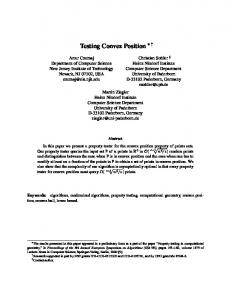
Fig. 2. ATM Use Case Diagram and the “Transactions” Use Case
the behavior of the ATM in a scenario-based style. A state-based C# model is used to describe the sub-behavior of the “bank” actor in the overall model, which maintains a data-base of customers and their accounts. 3.1
The ATM scenario model
Fig. 2 shows a screen shot of Visual Studio displaying the activity chart for one depicted use case. The model is built from four use cases, which are hierarchicaly organized. The top-level use case “Session” describes an interaction of a customer with the bank via the ATM system, the use case “Transactions” describes an iteration of transactions a customer can perform, and the use cases “Inquiry” and “Withdrawal” describe the individual transaction types. The activity diagram for the “Transactions” use case describes a loop where the user can enter a transaction type (variable ttype), and in dependency of that type the “Withdrawal” or the “Inquiry” use case is invoked, or processing further transactions is canceled. Such scenario descriptions might result from the requirements phase or from modeling test plans. In course of concretizing them for an analysis or testing problem, the so-far abstract nodes of the activity are mapped to action patterns. In the screen shot, the tool tip underneath the activity “Input Transaction Type” shows such a mapping. Namely, this activity is mapped to the action invocation console.InputTType(ttype), where console is a variable representing the customer console of the system, which 9
has been declared elsewhere. This mapping has been performed manually based on an underlying object model for the ATM, but it can be also performed automatically by synthesizing actions from the activity node name and the variables in scope. Variables in activity charts play an important role for the expressiveness of the approach, since they bound inputs and outputs from different activities together. All variables are purely declarative (logical variables). Flows can add constraints over those variables. Variables may be scoped inside iterations, like here the ttype variable. Action patterns might be more complex than just describing action invocations. They impose regular expression constructs plus all the composition operators available in the framework (see [7] for the action pattern language of SEVS ). The implementation of the activity chart shown in Fig. 2 is actually based on a translation into a single action pattern which looks as follows: ([TransactionType ttype] ( [. ttype == TransactionType.Withdrawal .] : Console.InputTType(ttype); Withdrawal(console,bank,cinfo) | [. ttype == TransactionType.Inquiry .] : console.InputTType(ttype); Inquiry(console,bank,cinfo) ) )* ([TransactionType ttype] [. ttype == TransactionType.Cancel .] : console.InputTType(ttype); console.DisplayCanceled() )
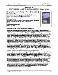
Here, the notation [T x]pat introduces a variable scoped over action pattern pat, and [.exp.]:pat stands for a constraint expressed by an embedded host language expression exp (which can be C#); the other constructs come from regular expressions. The action pattern language is the only “new” language which is introduced by SEVS . However, users do not need to know its full range of possibilities to use it. Given a scenario model as above, users can explore it under SEVS to visualize its behavior. Exploration yields in a graph as shown in Fig. 3. This graph is similar to the one shown in Sect. 2 for the old Spec Explorer tool and basically depicts an interface automaton [9], where nodes of the graph represent states and transitions action invocations. Round nodes are control points where input is provided to the system and diamond nodes represent observation points where output is observed from the system. Note how variable v5 in the left part of the graph (which represents the amount a user want to withdraw) express causalities which go beyond pure control flow: the same given amount in v2.InputAmount(v5) must also be withdrawn from the bank (v4.?TryWithdrawal(v1,v5)). However, the model has also some partiality: the value of variable v5 is not fixed, and the model does not contain any information when the verification of a pin (state S2) or the withdrawal from the bank (state S10) is actually successful; it only states what the successive behavior is supposed to be in either of that cases. 3.2
Refining the Bank
The behavior generated from the ATM model, as shown in Fig. 3, is partial regarding the behavior of the bank. While such a model can already be used for testing (after providing some additional information for parameter domains and traversals, and then applying test selection), it may miss some important parts: If the bank is “trivial”, that 10
Fig. 3. Exploration Graph Resulting from ATM Model
is always returns false on pin verification, no interesting tests are performed. Making the bank non-trivial can be either achieved in the manual setup for the test or can be modeled as well. Fig. 4 gives a state-based model of the bank in C#. The model introduces four actions: In addition to VerifyPIN and TryWithdrawal, which already appeared in the ATM scenario model, a constructor for the bank and an action SetCustomer is introduced which allows to add a customer with a given id, pin, and initial balance to the bank. The model uses library support to express pre-conditions (enabling conditions) of actions. Contracts.Requires(!pins.Contains(id)), for example, ensures that the action is only enabled if a customer with the given id is not yet added to the bank. This model could be explored, analyzed and converted to a test suite by itself. Obviously, it would suffer from the problem of state explosion, since its state space is unbounded. In order to test the bank standalone, one could provide a scenario which prunes the behavior. However, the focus here is on combining it with the ATM model given before to not only prune the model, but also yield a composed model which is richer than each individual model. A small piece of the action pattern language can be used for this purpose (in its intended final stage of expansion, SEVS will provide UI abstractions for defining such compositions). Let BankModel describe the model of the bank, and Session the model of the ATM, then the composition can be defined as follows: (new Bank();_.AddCustomer(1,1,10);Session()) |?| Bank() Here a scenario is constructed which creates a new bank, adds one customer, and then runs the Session scenario; this scenario is composed in parallel with the bank model 11
class Bank { MapContainer pins = new MapContainer(); MapContainer balances = new MapContainer(); Bank(){ pins = new MapContainer(); balances = new MapContainer(); } void AddCustomer(int id, int pin, int balance){ Contracts.Requires(!pins.Contains(id)); pins[id] = pin; balances[id] = balance; } bool VerifyPIN(int id, int pin){ return pins.Contains(id) && pins[id] == pin; } bool TryWithdrawal(int id, int amount){ Contracts.Requires(balances.Contains(id)); if (balances[id] >= amount){ balances[id] -= amount; return true; } else return false; } }
Fig. 4. Model of the Bank in C#
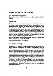
itself, where the |?| composition enforces synchronization of actions common to both operands, and allows interleaving of other actions. Note that since there is only one bank object ever created in this construction, an assignment to the bank receiver parameter can be left open, since there are no choices. Fig. 5 shows the result of exploring the given composition. The parameter for InputAmount was fixed to 10 (in practice, one could use a larger domain, but the result would be harder to understand for the purpose of this paper). With an additional balance of 10 and a withdrawal amount of 10, there are two states in the composed model from which the customer can make transactions: in state S6 she has 10 dollars on the account, whereas in state S16, she has zero dollars on the account. 3.3
What else?
The ATM sample showed only a fragment of the possibilities of the new tool. For example, the ATM scenario model could have been directly given in the action pattern language or defined programmatically. Fig. 6 gives an idea on how a programmed scenario looks like in AsmL (C# could have been used here as well). The SEVS implementation allows to create symbolic values in .NET programs. It is able to abstract the calls to actions over which a scenario program is defined. In other words, the action InputTType here is not really executed; instead, it will create a state transition in the generated behavior which is labeled with the action and its parameters. If an action is non-void the result will be represented by a free symbolic value. In its final stage of expansion, SEVS will also allow to represent state-based models using diagrams, namely, by supporting Statecharts. Other features which have been taken for granted here without deeper explanation are the possibility to explore symbolic state spaces, the traversal techniques and the parameter selection techniques, and, moreover, the possibility to run tests on-the-fly (before traversal) or to persist test suites as data or programs (after traversal). 12
Fig. 5. Exploration Graph Resulting from ATM Model in Composition with Bank Model
One application of SEVS which has not been shown as well is model-checking of temporal properties. This is supported by exploration of the parallel composition of anti-models – models whose behavior is unwanted – with regular models. If the result of this exploration is non-empty, it represents the “counter examples”. Anti-models can be directly written down by a user – in the form of anti-scenarios, for example – or generated from temporal formulas.
4
Foundations: Action Machines
This section provides to the interested reader a sketch of action machines, the underlying semantic and implementation framework of SEVS . For a complete description, see [6]. Action machines combine concepts from abstract state machines, finite automata, and labeled transition systems, and as such they constitute a novel hybrid. Their construction is motivated by the practical need to express data as well as control state, transitions which are labeled with actions, symbolic data and actions, and compositions of behavior, both in parallel and sequential style. In contrast to other approaches combining state and control based formalisms, action machines support full sharing of data 13
Transactions() var continue = true step while continue let ttype = Symbolic.Any() step console.InputTType(ttype) step match ttype Cancel : console.DisplayCanceled() continue := false Inquiry : Inquiry() Withdrawal : Withdrawal()
Fig. 6. Scenario Program for the Transactions Use Case in AsmL
state in compositions, which is essential for the application in SEVS . The formalization of action machines uses natural semantics [15] and is very close to the actual implementation. The implementation is based on the Exploring Runtime, a software-model checker for .NET [16]. Terms, Constraints, and Actions An abstract universe of terms over a given signature, t ∈ T, is assumed. Terms capture values in the domain of the modeling and implementation languages, constraints, as well as action labels. Terms also contain (logical) variables, V ⊆ T. The class of terms which represent constraints is C ⊆ T. The actual structure of constraints does not matter. However, it is assumed that C contains at least the tautology true, equivalences between terms (denoted as t1 ≡ t2 ), and is closed under conjunction (c1 ∧ c2 ). Terms have an interpretation in a mathematical value domain, D, which is described by a function ξT ∈ (V → D) × T → D. Given a value assignment to variable terms, the interpretation function delivers the value of the term in D. For constraint terms, the truth value in the interpretation image is denoted as trueD . The further explicit structure of terms does not matter here. However, to aid intuition, and for use in examples, the structure of terms that represent action labels is described in an instance of the framework where actions stand for method invocations. m(t1 , . . . , tn )/t denotes an action term representing a method invocation, where m is a symbol identifying the invoked method, ti are input arguments, and t is the returned value. The symbol m behaves for the term language like a free constructor (selfinterpreting function). Henceforth, two action labels are equivalent exactly when the action symbols are equal and the input and output terms are equivalent. During the rest of this section an oracle for renaming of variables in terms is used: rename(t) denotes the term t after renaming all variables to be distinct from other variables in use. Environments An environment, e ∈ E, is a representation of a (partial) global data state. Let L be a countable set of locations (global state variables). An environment is syntactically represented by a pair (α, c), where α ∈ L → 7 T is a partial function from locations to terms, and c ∈ C is a constraint. A model of an environment is represented by a (total) function Γ ∈ L → D; Γ is valid for e, denoted as Γ |= e, as follows: Γ |= e ⇔ ∃ v : V → D | ξT (v, ce ) = trueD ∧ ∀ l ∈ dom(αe ) · Γ (l) = ξT (v, αe (l)) 14
Note that locations not used by the environment can have arbitrary assignments in the model. The interpretation of an environment is the set of models it has, denoted as ξE (e) = {Γ | Γ |= e}. Environments are partially ordered by subsumption which directly maps to inclusion of environment model sets: e1 w e2 ⇔ ξE (e1 ) ⊇ ξE (e2 ). Subsumption e1 w e2 indicates that e1 is more general (contains less information) than e2 . This can be because e1 fixes less locations than e2 , or because its constraint is weaker. Equivalence on environments, as derived from the subsumption ordering, is denoted as e1 ≡ e2 , and coincides with model set equality. With the ordering v=w−1 , environments build a complete lattice [17] with meet (least upper bound) e1 t e2 = ξE (e1 ) ∪ ξE (e2 ), join (greatest lower bound) e1 u e2 = ξE (e1 ) ∩ ξE (e2 ), and top and a bottom elements >E and ⊥E , where >E = L → D is the set of all environment interpretations and ⊥E = ∅. In the construction of action machine transitions the transition label is stored in the environment instead of representing it explicitly. This greatly simplifies the formalization of synchronization in composition, which is performed both on target environments and labels. Let ν ∈ L denote a distinguished “scratch” location used for storing an action label. e[t] denotes the environment where the term t is assigned to the location ν, and all other locations are mapped to the assignment in e. Henceforth, dom(αe[t] ) = dom(αe ) ∪ {ν}, αe[t] (ν) = t and ∀ l ∈ dom(αe[t] ) · l 6= ν ⇒ αe[t] (l) = αe (l). Computable Operations on Environments Environment operations like joining are not computable in arbitrary term domains. The range of the computable part depends on the power of the underlying decision procedures (that is, a constraint solver or theorem prover), from which the formalization here intends to abstract. To this end, is a computable approximation to joining is defined. One writes (e1 uc e2 ) 7→ e3 to indicate that a join may result in an environment which has models. This operator is a relation on syntactic environment representations and is related to the model semantics as follows: (e1 uc e2 ) 7→ e3 ⇒ e1 ue2 ≡ e3 , and (¬ ∃ e3 ·(e1 uc e2 ) 7→ e3 ) ⇒ e1 u e2 ≡ ⊥E . The incompleteness of an underlying decision procedure is reflected as follows: If an operational join proceeds, the resulting environment might be infeasible (has no models), but it respects the model semantics. If an operational join does not proceed, then also the model join is empty. Similarly, a computable approximation to extending an environment by a constraint is required. Let c be a constraint. One writes (e1 ∧c c) 7→ e2 to denote that e2 is the extension of e1 by c. The constraint c might share variables with e1 . Extension is explained as follows: let e02 be constructed as (αe1 , [[ce1 ∧ c]]), then (e1 ∧c c) 7→ e2 ⇒ e2 ≡ e02 , and ¬ ((e1 ∧c c) 7→ e2 ) ⇒ e02 ≡ ⊥E . Machines Let E denote an environment domain as described above. An action machine is given as a tuple M = (C, A, I, T). C is a set of so-called control points, and A ⊆ C is a set of accepting control points. I ⊆ E × E × C is the initialization transition relation, and T ⊆ E × C × E × C is the (regular) transition relation. A pair of an environment and a control point is called a (machine) state and denoted as e · c ∈ E × C. Initialization transitions from I relate an environment with an initial machine state. One writes e1 −→M e2 · c2 for initialization transitions. Regular 15
(t0 , p0 , u) ∈ R
(t, p) = rename(t0 , p0 )
U1
t
(e[t] ∧c p) 7→ e0 [t0 ] e00 [t00 ] · c0 = u(e0 [t0 ])
00
e · c −→UI,R e00 · c0 t
P1
e −→M1 e0 · c1 e −→M1 ; M2 e0 · c1
e −→M1 e1 · c1
t
t
1 0 0 e · c −→ M 1 ; M 2 e1 · c1
t0
e · (c1 , c2 ) −→M1 kM2 e0 · (c01 , c02 )
S2
c1 ∈ AM1
e1 −→M2 e2 · c2
e −→M1 ; M2 e2 · c2 t
1 0 0 e · c −→ M 1 e1 · c1
S3
P2
e −→M1 kM2 e0 · (c1 , c2 )
S1
t
1 2 0 0 e · c1 −→ e · c2 −→ M 1 e1 · c1 M 2 e2 · c2 0 0 (e1 [t1 ] uc e2 [t2 ]) 7→ e [t ]
e −→M1 e1 · c1 e −→M2 e2 · c2 (e1 uc e2 ) 7→ e0
1 0 0 e · c −→ M 1 e1 · c1
S4
c01 ∈ AM1
e01 −→M2 e02 · c02
t
1 0 0 e · c −→ M 1 ; M 2 e2 · c2
Fig. 7. Guarded Update, Parallel, and Sequential Composition Rules
transitions from T lead from states to states; the action label is contained in the special t location ν of the target environment. For readability, one writes e1 · c1 −→M e2 · c2 for regular transitions, which is syntactic sugar for (e1 , c1 , e2 [t], c2 ) ∈ T. Initialization transitions are allowed to refine the environment, but not to change it. This is imposed by the following property which holds for every action machine M: ∀(e1 −→M e2 ·c2 ) ∈ I ·e1 w e2 . Such a refinement could be, for example, the allocation of a new location, or the strengthening of the environment constraint. Instances of Action Machines Some instances of action machines are defined to illustrate the approach. The guarded-update machine shows the principal way how statebased notations, like AsmL or C#, are mapped into action machines. The guardedupdate machine, UI,R = (C, A, I, T) is defined by a given initialization transition relation I and a set of rules R, (t, p, u) ∈ R, where t ∈ T is an action label term, p ∈ C is a constraint, and u ∈ E→E×C is an update function which maps a given environment to a new machine state. One has C = {�, ◦} and A = {◦}, that is the machine has exactly two control states, one of which is accepting and the other is not. The transition relation of the machine is defined by rule U1 in Fig. 7. The synchronized parallel composition of two action machines results in a machine that steps both machines simultaneously. A transition is only possible if the action labels and the target environments can be joined. Let M1 k M2 = (C, A, I, T) denote the parallel machine, where C = CM1 × CM2 and A = AM1 × AM2 . Rule P1 describes initialization transitions, while rule P2 describes regular transitions. The sequential composition of two machines, M1 ; M2 = (C, A, I, T), exhibits the behavior of M1 , and when M1 is at an accepting control point, it also exhibits transitions into M2 . One has C = CM1 ] CM2 and A = AM2 . The regular transitions of M2 are contained in T (TM2 ⊆ T). Rule S1 and rule S2 describe initialization transitions of this machine; in the case that an initial control point of M1 is accepting the machine offers also the initial control points of M2 . Rule S3 and S4 describe regular transitions; 16
similar as with initialization, if an accepting control point is reached, the transition is duplicated to also reach an initial control point of the second machine. Note that in [6] a slightly more complex definition of sequential composition is provided which avoids duplication of transitions. The definition given here is sufficient for illustration but less practical. The action machine framework provides many more composition operators, among the most interesting to mention are alternating simulation, hiding, and hierarchical composition. In order to formalize alternating simulation – the used testing conformance notion – in the presence of an incomplete decision procedure, [6] distinguishes between may and must transitions of action machines. May-transitions have been used in this paper. They represent an over-approximation and are thus safe (no false positives) when providing inputs to a system-under-test. However, for checking outputs of a system, must-transitions are required. The details can be found in [6]. Implementation The implementation of action machines is based on the Exploring Runtime (XRT) [16], a software model-checker and virtual execution framework for .NET which is based on byte code interpretation. XRT provides symbolic state representation and exploration of full .NET code. Action machines are realized as a layer on top of XRT. This layer takes environments as provided by XRT’s data state model and adds the constructs of action machines as a set of interfaces. Transition relations are described by lazy enumerations delivered by those interfaces. The interface abstraction is very close to the semantic model. The action machine coordination language, Cord [7], is a declarative intermediate notation which realizes a textual frontend to action machines. Apart from providing action patterns, as used before in this paper, and composition between machines, it allows the definition of configurations for model-based testing and model-checking problems, like parameter generators, exploration bounds, traversals, and so on.
5
Conclusion
Model-based testing promises a significant contribution in raising software testing to a systematic engineering discipline, and providing an entry door to model-based development. Its application for internal development at Microsoft for half a decade is considered a success, though a break-through of the technology is not in sight. This paper attempted to identify some of the obstacles for wider adoption of MBT at Microsoft, which are typical at least for software development at enterprise level. The conclusion drawn is that in order to address different concerns both inside the testing organizations as well as in the broader scope of model-based development, a model-based testing tool and approach should be multi-paradigmatic, supporting programmatic and diagrammatic notations, as well as state-based and scenario-based styles. Programmatic notations with decent authoring support should be provided for test engineers, best using mainstream programming languages, whereas diagrammatic, scenariobased notations as well as executable specification languages should be provided for test architects and stakeholders outside of the test organizations. Moreover, model-checking should be seen as an integral part of model-based testing tools. The paper sketched a new tool which is currently in development, “Spec Explorer for Visual Studio”, which 17
is designed from these goals, and proves that they are feasible. The semantic foundation of this tool, action machines, has been described as well. Whether the approach of this tool works in practice has to be validated once it has been rolled out to the internal Microsoft user community. The general message of the paper does not come as a surprise: Multi-paradigmatic approaches are ubiquitous in model-based development, as for example reflected in UML. However, model-based testing requires that there are full programmatic notations, and not only diagrammatic ones, and puts strong demands on the semantic and tool-technical integration of the various behavioral notations, requiring them to be composable for a common testing goal. This demand is indeed also a long term goal for model-based development in general – yet the model-based testing application provides very concrete requirements, the implementation of which promises immediate payoff. Acknowledgments Many thanks go to my colleagues Colin Campbell, Yuri Gurevich, Lev Nachmanson, Kael Rowan, Wolfram Schulte, Nikolai Tillmann and Margus Veanes, and the numerous enthusiastic users of MBT at Microsoft which have made this work possible. Special thanks go to Nicolas Kicillof and the reviewers for reading an early draft of this paper.
References 1. Harry Robinson. Finite state model-based testing on a shoestring. In STARWEST 99. available online. 2. Wolfgang Grieskamp, Yuri Gurevich, Wolfram Schulte, and Margus Veanes. Generating finite state machines from abstract state machines. In ISSTA’02, volume 27 of Software Engineering Notes, pages 112–122. ACM, 2002. 3. Mike Barnett, Wolfgang Grieskamp, Lev Nachmanson, Wolfram Schulte, Nikolai Tillmann, and Margus Veanes. Towards a tool environment for model-based testing with AsmL. In Petrenko and Ulrich, editors, Formal Approaches to Software Testing, FATES 2003, volume 2931 of LNCS, pages 264–280. Springer, 2003. 4. Keith Stobie. Model based testing in practice at microsoft. In Proceedings of the Workshop on Model Based Testing (MBT 2004), volume 111 of Electronic Notes in Theoretical Computer Science. Elsevier, 2004. 5. Colin Campbell, Wolfgang Grieskamp, Lev Nachmanson, Wolfram Schulte, Nikolai Tillmann, and Margus Veanes. Model-based testing of object-oriented reactive systems with Spec Explorer. Technical Report MSR-TR-2005-59, Microsoft Research, May 2005. to appear in Formal Methods and Testing, LNCS, Springer. 6. Wolfgang Grieskamp, Nicolas Kicillof, and Nikolai Tillmann. Action machines: a framework for encoding and composing partial behaviors. Technical Report MSR-TR-2006-11, Microsoft Research, February 2006. to appear in International Journal of Software & Knowledge Engineering. 7. Wolfgang Grieskamp and Nicolas Kicillof. A schema language for coordinating construction and composition of partial behaviors. In Proceedings of the 28th International Conference on Software Engineering & Co-Located Workshops – 5th International Workshop on Scenarios and State Machines. ACM, May 2006. 8. Y. Gurevich. Evolving Algebras 1993: Lipari Guide. In E. B¨orger, editor, Specification and Validation Methods, pages 9–36. Oxford University Press, 1995.
18
9. Luca de Alfaro and Thomas A. Henzinger. Interface automata. In Proceedings of the 8th European Software Engineering Conference and the 9th ACM SIGSOFT Symposium on the Foundations of Software Engineering (ESEC/FSE), pages 109–120. ACM, 2001. 10. Microsoft. The LINQ project. http://msdn.microsoft.com/data/ref/linq, 2006. 11. Wolfgang Grieskamp, Nikolai Tillmann, and Margus Veanes. Instrumenting scenarios in a model-driven development environment. Information and Software Technology, 2004. 12. J.C. Fernandez, C. Jard, T. J´eron, and C. Viho. An experiment in automatic generation of test suites for protocols with verification technology. Science of Computer Programming Special Issue on COST247, Verification and Validation Methods for Formal Descriptions, 29(1-2):123–146, 1997. 13. Jan Tretmans and Ed Brinksma. TorX: Automated model based testing. In 1st European Conference on Model Driven Software Engineering, pages 31–43, Nuremberg, Germany, December 2003. 14. Microsoft. Domain specific language tools. http://msdn.microsoft.com/vstudio/dsltools, 2005. 15. G. Kahn. Natural semantics. In Symposium on Theoretical Computer Science (STACS’97), volume 247 of Lecture Notes in Computer Science, 1987. 16. Wolfgang Grieskamp, Nikolai Tillmann, and Wolfram Schulte. XRT - Exploring Runtime for .NET - Architecture and Applications. In SoftMC 2005: Workshop on Software Model Checking, Electronic Notes in Theoretical Computer Science, July 2005. 17. B.A. Davey and H.A. Priestly, editors. Introduction to Lattices and Order. Cambridge University Press, 1990.
19