timing and continuous constraints on their behaviors, a model checker must keep ..... On the other hand CLP contains a constraint solver over symbolic domains, which ... is the name of the automaton itself, and Location represents the actual name ..... hybrid automata model-checking tool, one has to specify such model ...
/WNVK�4QDQV�5[UVGOU��/QFGNKPI��5RGEKſECVKQP��CPF�/QFGN�%JGEMKPI
���
�� 0 Multi-Robot Systems: Modeling, Specification, and Model Checking Ammar Mohammed and Ulrich Furbach University of Koblenz-Landau, Department of Computer Science Germany
Frieder Stolzenburg Harz University of Applied Sciences, Department of Automation and Computer Sciences Germany
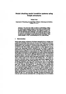
1. Introduction Specifying behaviors of physical multi-agent systems (MAS) – also called multi-robot systems – is a demanding task, especially when they are applied in safety critical applications. For this, formal methods based on mathematical models of the system under design are helpful. They allow us not only to formally specify the system at different levels of abstraction, but also to analyze the consistency of the specified systems before implementing them. The formal specification aims at both, a precise and unambiguous description of the behavior of MAS, and a formal verification whether a given specification is satisfied. For example, it should be possible to show that unsafe regions of the state space cannot be reached, or that a particular property is satisfied. Generally, the behavior of an agent in MAS can be driven by external events and internal states. Therefore, an efficient way to model such systems is to use state transition diagrams, which are well established in software engineering. A state transition diagram describes the dynamic behaviour of an agent in terms of how the agent acts in certain scenarios of the simple simple plyer player line up
line up kick off attack
team lost ball
line up
defend
team got ball game over
game over
Fig. 1. A description of a simple agent in robotic soccer as a transition system.
���
4QDQV�5QEEGT
environment. It aims at defining the behavior rules for the agents of the system. For example, Fig. 1 shows the behavior of an abstract simple agent/player in robotic soccer modeled as a state transition diagram. The agent may either defend or attack, depending on which team is controlling the ball. All changes of such global behaviors happen in response to one or more external events. Generally, state transition diagrams have been applied successfully for MAS, particularly in the RoboCup, a simulation of (human) soccer with real or virtual robots (cf. Arai & Stolzenburg, 2002; da Silva et al., 2004), in particular for the teams RoboLog Koblenz (two-dimensional simulation league) and Harzer Rollers (standard four-legged league) (Murray et al., 2002; Ruh & Stolzenburg, 2008). In realistic physical environments, it is necessary to consider continuous actions in addition to discrete changes of the behaviors. Take for example, the movement of a soccer agent to kick off or to go to the ball, the process of putting out the fire by a fire brigade agent in a rescue scenario, or any other behaviors that depend on any timed physical law. Hybrid automata (Henzinger, 1996) offer an elegant method to model such types of behaviors. Basically, hybrid automata extend regular state transition diagrams with methods that deal with those continuous actions. The state transition diagrams are used to model the discrete changes of the agents’ behavior, while differential equations are used to model the continuous changes. The semantics of hybrid automata make them accessible to a formal validation of systems, especially for those systems which are situated in safety critical environments. Model checking can be used to prove desirable features or the absence of unwanted properties in the specified systems (Clarke et al., 1999). Specifying and verifying behaviors of MAS by means of hybrid automata is challenging for many reasons. One of those is a state space problem: Essentially, MAS are specified as concurrent automata that have to be composed in parallel. The result of this composition captures all possible behaviors that may occur among the agents, which can be checked by hybrid automata verification tools (Behrmann et al., 2004; Frehse, 2005; Henzinger et al., 1995b). Obviously, this composition process may lead to a state explosion. Another problem is that hybrid automata describe not only the internal behaviors of agents, but also the external interaction among agents. This definitely adds complexity, which demands for structured and systematic methods for the specification of MAS. We propose to combine hybrid automata with software engineering methods to overcome these problems. In this chapter, we provide a framework based on hybrid automata, which allows us to conveniently specify and verify physical MAS situated in a continuous dynamic environment. We will address the state space complexity raised from composition of agents, by composing the automata dynamically during the verification phase. This can relieve the problem in such a way that only the exact reached parts of the state space are activated, instead of activating all the entire state space at once. Furthermore, in order to cope with complex multi-agent structures, we combine hybrid automata with hierarchical UML statecharts, which allows MAS specification with different levels of abstraction. We also give a formal semantics for this combination, and show how to analyze the dynamic behaviors of MAS. In principle, a straightforward way to analyze a hierarchical machines is to flatten them and to apply verification techniques to the resulting ordinary finite state machines. We show how this flattening can be avoided.
2. Hybrid Finite State Machines Originally, hybrid automata (Henzinger, 1996) have been proposed as formal models for describing hybrid systems. They have been built as a generalization of timed automata (Alur & Dill, 1994), which have been used successfully as a standard framework to specify real-time
/WNVK�4QDQV�5[UVGOU��/QFGNKPI��5RGEKſECVKQP��CPF�/QFGN�%JGEMKPI
���
systems. In addition to their mathematical models to formally specify and verify systems, the underlying mathematical models of hybrid automata can be represented graphically as a finite state machine (FSM). There are several approaches to apply this framework to MAS (see e.g. Egerstedt, 2000; Furbach et al., 2008; Mohammed & Furbach, 2008a). In order to specify MAS by means of hybrid automata, the team of agents is described as concurrent automata, which in turn are combined via parallel composition into a global automaton, in order to coordinate their behaviors for reaching a common goal. It is well known that the major problem in applying model checking to analyze concurrent systems is the potential combinatorial explosion of the state space arising from parallel composition. Typically the state space of the parallel composition of an agent with K1 states and another agent with K2 states leads to a state space of K1 × K2 states. Accordingly, the parallel composition of N agents, each with a state space of K states, leads to a state pace of K N states. Even for small systems this may easily run out of control. Additionally, the state explosion problem is even more serious in verifying continuous dynamic systems. As such systems must satisfy certain timing and continuous constraints on their behaviors, a model checker must keep track not only of the part of the state space explored, but also of timing and continuous evolution information associated with each state, which is both time and space consuming. Traditionally, global state-space representations are constructed without regard to whether the states are reachable or not. In this section we will give a framework where the state space is built on the fly during the execution of the concurrent MAS. This can relieve the complexity in a sense that only the active parts of the state space will be taken into consideration during the run, instead of producing the composition prior to the verification phase. In this section we will define the syntax and the semantics of our framework. Additionally, we will show how the composition of automata can be formally constructed. Finally, we will use constraint logic programming to implement the proposed framework. All this will be exemplified by a simple rescue scenario. 2.1 Rescue Scenario: Example
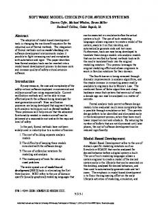
In the RoboCup rescue simulation league (Tadokoro et al., 2000), a large scale disaster is simulated. The simulator models part of a city after an earthquake. Buildings may be collapsed, or are on fire, and roads are partially or completely blocked. A team of heterogeneous agents consisting of police forces, ambulance teams, a fire brigade, and their respective headquarters is deployed. The agents have two main tasks, namely finding and rescuing the civilians and extinguishing fires. An auxiliary task is the clearing of blocked roads, such that agents can move smoothly. As their abilities enable each type of agent to solve only one kind of task (e.g. fire brigades cannot clear roads or rescue civilians), the need for coordination and synchronization among agents is obvious in order to accomplish the rescue tasks. Now, consider the following simple scenario. If a fire breaks out somewhere, a fire brigade agent is ordered by its headquarters to extinguish the fire. The fire brigade agent moves to the fire and begins to put it out. If the agent runs out of water, it has to refill its tank at a supply station and return to the fire to fulfill its task. Once the fire is extinguished, the fire brigade agent is idle again. An additional task of the agent is to report any injured civilians it discovers. In addition to the fire brigade agent, the model should include a fire station, fire, and civilians in the environment. A part of this scenario, specified as hybrid automata, is depicted in Fig. 2. The complete description and specification of the scenario will be shown in Sec. 3 (cf. Fig 4).
���
4QDQV�5QEEGT
Fire no fire boom = 0 i: boom ≤ 3 ˙ =1 f: boom
boom = 3/neededw� = 120 burn
burning i: neededw > 0 ˙ =0 f: boom
neededw = 0
put out i: true ˙ =0 f: boom
Civilians injured w = 10 i: w ≥ 0 f: w˙ = −1 FirebrigadeMain
move2supply
w = 0/w� = 10
wLevel = wlMax ∧ neededw > 0 / refill m2ftime� = tSupply i: wLevel ≤ wlMax ˙ f: wLevel = rFill
m2stime = 0
i: m2stime ≥ 0 ˙ f: m2stime = −1
help
wLevel = wlMax ∧neededw = 0 ∧civ = 0 idle i: true
wLevel = wlMax ∧ neededw = 0
true /m2ftime� = 3 emergency
reported
civ > 0/ civ� = civ − 1
wLevel = 0/m2stime� = tSupply
move2fire i: m2ftime ≥ 0 ˙ f: m2ftime = −1
neededw = 0 ∧ wLevel > 0
extinguish i: wLevel ≥ 0 ˙ f: wLevel = −rExt ˙ neededw = −rExt
m2ftime = 0
Fig. 2. A part of the RoboCup rescue scenario specified as hybrid automata.
As depicted in Fig. 2, the behavior of the agent FirebrigadeMain consists of five states corresponding to movements (move2fire, move2supply), extinguishing (extinguish), refilling the tank (refill), and an idle state (idle). It can report the discovered civilians when it is in its idle state. Details of this figure will be explained in details during this chapter. It should be obvious that even in this simple case with very few components, it is difficult to see if the agent behaves correctly. Important questions like: - Does the fire brigade agent try to extinguish without water? - Will every discovered civilian (and only those) be reported eventually? depend on the interaction of all components and cannot be answered without an analysis of the whole system. 2.2 Syntax
Since we intend to specify a multi-agent system with hybrid automata, the intuitive meaning of an agent is a hybrid automaton, which is represented graphically as a finite state machine, augmented with mathematical formalisms on both transitions and control states. Formally speaking, a hybrid automaton (agent with continuous actions) is defined as follows: Definition 2.1 (basic components). A hybrid automaton is a tuple H = ( Q, X, Inv, Flow, E, Jump, Reset, Event, σ0 ) where:
/WNVK�4QDQV�5[UVGOU��/QFGNKPI��5RGEKſECVKQP��CPF�/QFGN�%JGEMKPI
���
• Q is a finite set of locations which defines the possible behaviors of the agent. For example, in Fig. 2, the FirebrigadeMain agent has the locations move2fire, move2supply, extinguish, refill, and idle as possible behaviors. On the other hand, the Fire has no fire, burning and put out as its locations. It should be mentioned that we use the concept location instead of state, because an agent possesses different states inside each location, which are raised as a reason of continuous evolution. This will be described later in more details. • X = { x1 , x2 , ..., xn } is a finite set of n real-valued variables, including the variable t that denotes the time. These variables will be used to model the continuous dynamics of the automaton with respect to t. For example, the variable wLevel represents the amount of water of the fire brigade, and it can be used to model the rate of change to refill or flow the water with respect to the time inside the tank. On the other hand, the variable m2ftime represents the distance to the fire, and its rate of change with respect to the time models the speed of the fire brigade agent. • Inv is a mapping which assigns an invariant condition to each location q ∈ Q. The invariant condition Inv(q) is a predicate over the variables in X. The control of a hybrid automaton will remain at a location q ∈ Q, as long as Inv(q) holds. In the graphical representation, the invariant is tagged with the symbol i:. For instance the invariant wlevel≤ wlMax inside the location refill of FirebrigadeMain shows that the fire brigade fills the water as long as the water level does not reach the maximum level represented by the wlMax. Conventionally, writing Inv(q)[v] means that the invariant condition inside the location q holds, whenever the valuations of variables inside q are v. • Flow is a mapping, which assigns a flow condition to each control location q ∈ Q. The flow condition Flow(q) is a predicate over X that defines how the variables in X evolve over the time t at location q. In the graphical representation, it is tagged with the symbol f:. A flow of a variable ˙ ˙ In our example, the dotted variable wLevel x is denoted as x. describes the change of the water level in the location refill. The flow inside locations may be empty and hence omitted, if nothing changes continuously in the respective location. • E ⊆ Q × Q is the discrete transition relation over the control locations. • Jump is a mapping which assigns a jump condition (guard) to each transition e ∈ E. The jump condition jump(e) is a predicate over X that must hold to fire e. Omitting a jump condition on a transition means that the jump condition is always true and it can be taken at any point of time. In the rescue example Fig. 2, the jump condition between the locations extinguish and move2supply is given as wLevel=0, which means that the transition between these locations can be taken whenever wLevel reaches to 0. Conventionally, writing Jump(e)[v] means that the jump condition on a transition e holds, when the valuations of variables on the transition are v. • Reset is a mapping, which assigns values to variable to each transition e ∈ E. Reset(e) is a predicate over X that defines how the variables are reset. In the graphical representation, resetting a variable x ∈ X is denoted as x � . For example, when the transition between location refill and move2fire holds, the action m2ftime� = tSupply is executed, which means that the variable m2ftime is reset to the value tSupply.
���
4QDQV�5QEEGT
Resetting variables are omitted on transition, if the values of the variables do not change before the control goes from a location to another. • Event is a mapping which assigns an event to each transition e ∈ E from a set of events Event H . For instance, the transition between the locations idle and move2fire in FirebrigadeMain has emergency as its event. As we will see later, Event H is used to synchronize the automaton H with any other automata that share the same common events. It should be noted that in the graphical diagrams, an event Event(e) ∈ Event H is implicitly omitted, if it is not shared among any automata. • σ0 is the initial state of the automaton. It defines the initial location together with the initial values of the variables X. For example, the initial state of the agent FirebrigadeMain is the location idle with initial valuations wLevel = wl Max, neededw = 0, and civ = 0 to its variables wLevel, neededw, and civ respectively. Before describing the semantics of a hybrid automaton, it should be mentioned that the hybrid automata are classified according to the type of continuous flow: • If x˙ = c (constant), then the hybrid automaton is called linear hybrid automaton. A special case of linear hybrid automata are timed automata (Alur & Dill, 1994), where c = 1). • If c1 ≤ x˙ ≤ c2 , then the hybrid automaton is called rectangular hybrid automaton. • If x˙ = c1 x + c2 , then the hybrid automaton is called non-linear hybrid automaton. 2.3 Semantics
Intuitively, a hybrid automaton can be in exactly one of its control locations at each stage of it computation. However, knowing the present control location is not enough to determine which of the outgoing transitions can be taken next, if any. A snapshot of the current state of the computation should also remember the present valuation of the continuous variables. Therefore, to formalize the semantics of a hybrid automaton, we first have to define the concept of a state. Definition 2.2 (State). At any instant of time, a state of a hybrid automaton is given by σi =
qi , vi , t�, where qi ∈ Q is a control location, vi is the valuation of its real variables, and t is the current time. A state σi = qi , vi , t� is admissible if Inv(qi )[vi ] holds (i.e., the valuations of the variables satisfies the invariant at location qi . A state transition system of a hybrid automaton H starts with the initial state σ0 = q0 , v0 , 0�, where the q0 and v0 are the initial location and valuations of the variables respectively. For example, the initial state of the Civilians (see Fig. 2 ) can be specified as injured, 10, 0�. Informally speaking, the semantics of a hybrid automaton is defined in terms of a labeled transition system between states. Generally, transitions between states are categorized into two kinds of transitions: continuous transitions, capturing the continuous evolution of states, and discrete transitions, capturing the changes of location. More formally, we can define hybrid automaton semantics as follows. Definition 2.3 (Operational Semantic). A transition rule between two admissible states σ1 =
q1 , v1 , t1 � and σ2 = q2 , v2 , t2 � is
/WNVK�4QDQV�5[UVGOU��/QFGNKPI��5RGEKſECVKQP��CPF�/QFGN�%JGEMKPI
���
discrete iff e = (q1 , q2 ) ∈ E, t1 = t2 and Jump(e)[v1 ] and Inv(q2 )[v2 ] hold. In this case an event a a ∈ Event occurs. Conventionally, we write this as σ1 → σ2 . continuous(time delay) iff q1 = q2 , and t2 > t1 is the duration of time passed at location q1 , during which the invariant predicate Inv(q1)[v1 ] and Inv(q1)[v2 ] holds. In the previous definition, it should be noted that v2 results from resetting variables on a transition in case of the discrete transition rule, while it results from the continuous evolution of the variables in case of the continuous transition rule. Intuitively, an execution of a hybrid automaton corresponds to a sequence of transitions from a state to another. Therefore we define the valid run as follows. Definition 2.4 (Run: micro level). A run of a hybrid automaton ∑ = σ0 σ1 σ2 , . . . , is a finite or infinite sequence of admissible states, where the transition from a state σi to a state σi+1 is related by either a discrete or a continuous transition and σ0 is the initial state. It should be noted that the continuous change in the run may generate an infinite number of reachable states. It follows that state-space exploration techniques require a symbolic representation way in order to represent the set of states in an appropriate way. A good way is to use mathematical intervals. This interval captures all possible states. We call this interval region, which is defined as follows: Definition 2.5 (Region). given a run ∑, a sub-sequence of states Γ = (σi+1 · · · σi+m ) ⊆ ∑ is called a region, if for all states σi+ j with 1 ≤ j ≤ m, it holds qi+ j = q and if there exist a state σi and a state σi+m+1 with respective locations q1 and q2 , then it must hold q1 = q and q2 = q. Conventionally, a region Γ is written as Γ = q, V, T �, where ti+1 ≤ T ≤ ti+m is the interval of continuous time, and V is the set of intervals Vk of the interval defined by the values of xk ∈ X in the time interval T. A region Γ is called admissible if each state σ ∈ Γ is admissible. The previous definition reveals that a region captures the possible states that can be reached using continuous transitions in each location q ∈ Q. Therefore, T represents the continuous reached time. Additionally, a region captures the continuous values for each variable xi ∈ X. These continuous values can be represented as an interval Vi of real values. Therefore, V = {V1 , V1 , ..., Vn } represents a set of intervals of the variables in X. Now, the run of hybrid automata can be rephrased in terms of reached regions, where the change from one region to another is fired using a discrete step. Definition 2.6 (Run: macro level). A run of hybrid automaton H is ∑ H = Γ0 Γ1 , ..., a sequence of (possibly infinite) admissible regions, where a transition from a region Γi to a region Γi+1 is enabled a a (written as Γi → Γi+1 ), if there is σi → σi+1 , where σi ∈ Γi , σi+1 ∈ Γi+1 and a ∈ Event is the generated event before the control goes to the region Γi+1 . Γ0 is the initial region obtained from a start state σ0 by means of continuous transitions. The operational semantics is the basis for verification of a hybrid automaton. In particular, model checking of a hybrid automaton is defined in terms of the reachability analysis of its underlying transition system. The most useful question to ask about hybrid automata is the reachability of a given state. Thus, we define the reachability of states as follows. Definition 2.7 (Reachability). A region Γi is called reachable in ∑ H , if Γi ⊆ ∑ H . Consequently, a state σj is called reachable, if there is a reached region Γi such that σj ∈ Γi
���
4QDQV�5QEEGT
The classical method to compute the reachable states consists of performing a state space exploration of a system, starting from a set containing only the initial state and spreading the reachability information along control locations and transitions until fixed regions are obtained. Stabilization of a region is detected by testing, whether the current region is included in the union of the reached regions obtained in previous steps. It is worth mentioning that checking reachability for hybrid automata is generally undecidable. However, under various constraints, reachability is decidable for certain classes of hybrid automata including timed and initialized rectangular automata (Henzinger et al., 1998). A rectangular automaton is initialized if each continuous variable is reset every time a discrete transition is taken. 2.4 State Machine Composition
For the specification of complex systems, we extend hybrid automata by parallel composition. Basically, the parallel composition of hybrid automata can be used for specifying larger systems (multi-agent systems), where a hybrid automaton is given for each part of the system, and communication between the different parts may occur via shared variables and synchronization labels. Technically, the parallel composition of hybrid automata is obtained from the different parts using a product construction of the participating automata. The transitions from the different automata are interleaved, unless they share the same synchronization label. In this case, they are synchronized on transitions. As a result of the parallel composition a new automaton called composed automaton, is created, which captures the behavior of the entire system. In turn, the composed automata are given to a model checker that checks the reachability of a certain state. It is of advantage to do this during the verification process, instead of constructing the parallel composition before involving in the verification phase. Intuitively, the composition of hybrid automata H1 and H2 can be defined in terms of synchronized or interleaved regions of the regions produced from run of both H1 and H2 . As a result from the composition procedure, compound regions are constructed, which consists of a conjunction of a region Γ1 = q1 , V1 , T � from H1 and another region Γ2 = q2 , V2 , T � from H2 . Therefore, each compound region takes the form Λ = (q1 , V1 ), (q2 , V2 ), T � (shortly written as Λ = Γ1 , Γ2 , T �), which represents the reached region at both control locations q1 and q2 the during a time interval T. Now the run of composed automata can be defined as the sequence ∑ H1 ◦ H2 = Λ0 , Λ1 , ... of compound regions, where a transition between compound regions Λ1 = Γ1 , γ1 , T1 � and Λ2 = Γ2 , γ2 , T2 � a (written as Λ1 → Λ2 ) is enabled, if one of the following holds: a
a
• a ∈ Event H1 ∩ Event H2 is a joint event, Γ1 → Γ2 , and γ1 → γ2 . In this case , we say that the region Γ1 is synchronized with the region γ1 . a
• a ∈ Event H1 \ Event H2 (respectively a ∈ Event H2 \ Event H1 ), Γ1 → Γ2 and γ1 → γ2 , such that both γ1 and γ2 have the same control location (i.e., they relate to each other using a continuous transition). The previous procedures give the possibility to construct the composition dynamically during the run/verification phase. Obviously, as it has been said, computing the composition in such a way is advantageous. This is because only the active parts of the state space will be taken into consideration during the run instead of producing the composition procedure prior to the verification phase. This can relieve the state space problem raised from modeling multi-agent systems. In the following, we show how the previous procedure can be performed with the help of constraint logic programming.
/WNVK�4QDQV�5[UVGOU��/QFGNKPI��5RGEKſECVKQP��CPF�/QFGN�%JGEMKPI
���
2.5 Constraint-Based Modeling
In Mohammed & Furbach (2009) we showed how to encode the syntax and semantics of hybrid automata, described previously, as a constraint logic program (CLP) (Jaffar & Lassez, 1987). A primary version of this model was given by Mohammed & Furbach (2008b). There are diverse motivations beyond choosing CLP as a modeling prototype to implement the framework. Firstly, hybrid automata can be described as a constraint system, where the constraints represent the possible flows, invariants, and transitions. Secondly, constraints can be used to characterize certain parts of the state space (e.g., the initial states or a set of unsafe states). Further, there are close similarities in operational semantics between CLP and hybrid automata. Ideally, state transition systems can be represented as a logic program, where the set of reachable states can be computed. Moreover, constraints enable us to represent infinite states symbolically as a finite interval. For instance, the infinite states can be handled efficiently as an interval constraint that bounds the set of infinite reachable state as a finite interval (i.e., 0 ≤ X ≤ 250). Hence, a constraint solver can be used to reason about the reachability of a particular state inside this interval. A further motivation to choose CLP is its enrichment with many efficient constraint solvers of various domains. For example, CLP contains a constraint solver over real interval constraints, which can be used to represent the continuous flows as constraint relations to the time, as well as to reason about a particular valuation. On the other hand CLP contains a constraint solver over symbolic domains, which are appropriate to represent the synchronization events (communication messages) among agents. Last but not least, by employing CLP the automata composition can be constructed on the fly (during models checking). This can be done by investigating the constraints appeared during running models. In turn, the previous can relieve the state space problem raised from specifying MAS. Our implementation prototype was built using ECLiPSe Prolog (Apt & Wallace, 2007). The prototype follows the definitions of both the formal syntax and semantics of hybrid automata, which are defined in the previous section. To start implementing a hybrid state machine, we primarily begin with modeling the locations and their constraints (e.g. flows, invariants), which are modeled as the predicate automaton as follows: %%% automaton(+Location,?Vars,+Vars0,+T0,?Time) %%% models invariant and flow inside location automaton(Location,Vars,Vars0,T0,Time):Flow(Vars), Inv(Vars),Time $>=T0.
Here, automaton is the name of the automaton itself, and Location represents the actual name of the current locations of the automaton. Vars is a list of real variables participating in the automaton, whereas Vars0 is a list of the corresponding initial values. Inv(Vars) is the list of invariant constraint on Vars inside the location. The constraint predicate Flow(vars) models the continuous flows of the variables Vars with respect to time T0 and Time, given initial values Vars0 of the variables Vars at the start of the flow. T0 is the initial time at the start of the continuous flow. As it has been described in Subsection 2.2, a hybrid automaton is classified according to the constraints on the continuous flow. Therefore, Flow(Vars) is represented in terms of constraints as Vars = Var0 + c · ( Time − T0) in case of a linear hybrid automaton, as Var0 + c · ( Time − T0) ≤ Vars ≤ Var0 + c · ( Time − T0) in case of a rectangular hybrid automaton, and as Vars = Var0 − c2/c1 + c2/c1 · exp(c1 · ( Time − T0)) in case of a non-linear hybrid automaton. Here, ( Time − T0) models the delay inside the location. It should be noted
���
4QDQV�5QEEGT
that after executing the predicate automaton, Vars and Time holds the reached valuations of the variables together with the reached time respectively. The following is an example showing the concrete implementation of the location injured in the automaton Civilians Fig. 2. The $ symbol in front of the (in)equalities is the constraint relation for interval arithmetic constraints (library ic in ECLiPSe Prolog). civilians(injured,[W],[W0],T0,Time):W $= W0-(Time-T0), W $>=0, Time $>=T0.
According to operational semantics defined in Def. 2.3, a hybrid automaton has two kinds of transitions: continuous transitions, capturing the continuous evolution of variables, and discrete transitions, capturing the changes of location. For this purpose, we encode transition systems into the predicate evolve, which alternates the automaton between a discrete and a continuous transition. The automaton evolves with either discrete or continuous transitions according to the constraints appearing during the run. %%% evolve(+Automaton,+State,-Nextstate,+T0,+Time,?Event) evolve(Automaton,(L1,Var1),(L2,Var2),T0,Time,Event) :continuous(Automaton,(L1,Var1),(L1,Var2),T0,Time,Event); discrete(Automaton,(L1,Var1),(L2,Var2),T0,Time,Event).
When a discrete transition occurs, it gives rise to updating the initial variables from Var1 into Var2, where Var1 and Var2 are the initial variables of locations L1 and L2 respectively. Otherwise, a delay transition is taken using the predicate continuous. It is worth noting that there are infinite states due to the continuous progress. However, this can be handled efficiently as an interval constraint that bounds the set of infinite reachable state as a finite interval (i.e., 0 ≤ X ≤ 250). In addition to the variables, each automaton is augmented with a set events called Event Automaton . An example of this set of events of the automaton FirebrigadeMain is denoted as {reported, emergency}. For this reason, each transition is augmented with the variable Event, which is used to define the parallel composition from the automata individuals sharing the same event. The variable Event ranges over symbolic domains and guarantees that whenever an automaton generates an event, the corresponding synchronized automata have to be taken into consideration simultaneously. It should be mentioned that the declaration of automata events must be provided in the modeling example. For instance, the declaration of the possible events domain of Fig. 2. is coded as follows : :- local domain(events(emergency,reported,hlep,burn)).
This means that the domains of events are declared symbolically to capture the set of all possible events applicable to the underlying modeled system. The appropriate solver of a symbolic domain deals with any defined constraints in terms of the declared domains. Now after defining the domains of events, a variable of type events can be declared as follow: Event &:: events, Event &= domain_value.
The variable Event is declared with domain values defined by events, and is initialized with a specific value from its domain. The & symbol is a constraint relation for symbolic domains (library sd in ECLiPSe Prolog). The following is the general implementation of the predicate discrete, which defines transitions between locations.
/WNVK�4QDQV�5[UVGOU��/QFGNKPI��5RGEKſECVKQP��CPF�/QFGN�%JGEMKPI
���
%%% driver(+State1,+State2,...,+Staten,+T0,-Regions,+PastRegion). %%% perform composition and reachability driver((L1,Var01),(L2,Var02),...,(Ln,Var0n),T0,[Reg|NxtReg],PastReg) :automaton1(L1,Var1,Var01,T0,Time), automaton2(L2,Var2,Var02,T0,Time), ... , automatonn(Ln,Varn,Var0n,T0,Time), evolve(automaton1,(L1,Var01),(NxtL1,Nvar01),T0,Time,T,Event), evolve(automaton2,(L2,Var02),(NxtL2,Nvar02),T0,Time,T,Event), ... , evolve(automatonn,(Ln,Var0n),(NxtLn,Nvar0n),T0,Time,T,Event), \+ member((L1,L2,..,Ln,Var1,Var2,..,Varn,_,Event), PastReg), Reg = (L1,L2,..,Ln,Var1,Var2,..,Varn,Time,Event), NpastReg =[Reg|PastReg], driver((NxtL1,Nvar01),(NxtL2,Nvar02),...,(NxtLn,Nvar0n),T,NxtReg,NpastReg).
Fig. 3. A state machine to drive the execution of automata.
%%% discrete(+Automaton,+State1,-State2,+IntTime,-Time,-Event) discrete(Automaton,(Loc1,Var1),(Loc2,Var2),T0,Time,Event):automaton,(Loc1,Var1,Var,T0,Time), jump(Var), reset(Var2), Event &::events,Event &=domain_value.
In the previous predicate, domain_value must be a member in Event Automaton . Here, when the discrete predicate is fired, the automaton generates an event by constraining the variable Event to the suitable value from its domain. The following is an instance showing the concrete implementation of the discrete predicate between locations no fire and burning in automaton fire. discrete(fire,(no_fire,[B0,N0]),(burning,[BB0,NN0]),T0,Time,Event):fire(no_fire,[B0,N0],[BB0,NN0],T0,Time), BB0 $=3, NN0 $=120, Event &::events, Event &=burn.
Once the locations and transition rules have been modeled, a state machine needs to be implemented in order to execute the model. For this purpose, a driver program is implemented as shown in Fig. 3. The driver is a state machine that is responsible to generate and control the behaviors of the concurrent hybrid automata, as well as to provide the reachable regions symbolically. The driver takes the starting state for each participating automaton (i.e. a control location as input argument as well as the list of initial valuations of the variables). In addition, it takes the starting time T0 as begin of the execution, followed by the list of reached regions, which is needed for the purpose of the verification. It should be noted that during the course of the execution of the driver, there is a symbolic domain variable Event shared among automata, which is used by the appropriate solver to ensure that only one event is generated at a time. Precisely when an automaton generates an event, due to a discrete transition of one of the predicates evolve of the concurrent automata, the symbolic domain solver will exclude all the
���
4QDQV�5QEEGT
domain of values of the other automata that are not coincident with the generated event. This means that only one event is generated at a time. If more than one automaton generates different events at the same point of time, then the symbolic domain solver will handle only one of them at a time, but the other events will be handled using backtracking. Since each automaton generates an event by a discrete step at the end of its continuous evolution, then the precedence of events that appear during the run is important to both composition and the verification process. For this reason, an obvious way to deal with this precedence is to use constraints on the time of the generated events. To accomplish this, we constraint the execution of each automaton with a shared variable Time. The constraint solver, in turn, binds this variable with the minimum execution time among the automata. It follows that this variable Time eventually holds the minimum time needed to generated an event. The previous computation partitions the state space into regions, where the transition from one region to another depends on the minimum time needed to generate an event. Consequently, this shows how the automata composition can be implicitly constructed efficiently on the fly (i.e. during the computation). It has been said that we are not only concerned with running and composing the automata, but also with the their verification. For this purpose, the driver is augmented with the list of reached compound regions. At each step of the execution of the driver execution, a compound region, of the form locations, Variables, Time, Event� is added to the list of reached regions. This region symbolically represents the set of reached states and times to each control location as mathematical constrains. Additionally, each region contains the generated event before the control goes to another region using a discrete step. Technically, the driver computes the set of reached regions until fixed regions are obtained. This is computed by checking, in each iteration of driver, if the reached region is not contained in the list of the previously reached regions. For this purpose, the last argument of the driver holds for the list of these regions. Due to the undecidability of hybrid automata (Henzinger et al., 1998), the termination of the driver to reach to a fixed regions is not guaranteed generally. To overcome the non termination problem, we augment the predicate driver with a depth limit, by which the driver is enforced to stop upon reaching a given depth. Reachable regions should contain only those variables, which are important for the verification of a given property. Therefore, the last argument list of the predicate driver can be expanded or shrunk as needed to contain the significant variables. As soon as the driver has been built, the complete model should be invoked for the purpose of execution and hence verification. For this reason, the predicate runmodel is implemented to invoke the driver with the initial states of the hybrid automata. An example showing how to query the driver on the running scenario (see Fig. 2) takes the form:
runmodel(Reached) :driver((idle,[wlMax,0,0]),(injured,[10]),(no_fire,0),0,Reached,[]).
2.5.1 Verification as Reachability Analysis
Now we have an executable constraint-based specification, which can be used to verify properties of a multi-agent system. In particular, one can check properties on states using reachability analysis. For this we have two basic steps. Firstly, we compute the state space of the automaton under consideration by using the predicate driver. Secondly, we search for states
/WNVK�4QDQV�5[UVGOU��/QFGNKPI��5RGEKſECVKQP��CPF�/QFGN�%JGEMKPI
���
that satisfy or contradict given properties. This is done with the help of standard Prolog predicates like member/2 and append/3. Thus it is possible to implement our entire framework by some very simple Prolog rules. In terms of CLP, a state is reached iff the constraint solver succeeds in finding a satisfiable solution for the constraints representing the intended state. In other words, assuming that Reached represents the set of all reachable states computed by the CLP model from an initial state, then the reachability analysis can be generally specified, using CLP, by checking whether Reached |= Ψ holds, where Ψ is the constraint predicate that describes a property of interest. In practice, many problems to be analyzed can be formulated as a reachability problem. For example, a safety requirement can be checked as a reachability problem, where Ψ is the constraint predicate that describes forbidden states, and then the satisfiability of Ψ wrt. Reached is checked. An example would be to check that the state where the fire can be put out is reached. The following very simple CLP query gives us the answer yes: ?- runmodel(L), member((_firebrigade,_civilian,Fire,_var1,_var2,_var3,_time,_event),Reached), Fire $=put_out.
Other properties concerning the reachability of certain states can be verified similarly. Additionally, constraint solvers can be used to reason about the reachability of interesting properties within a region, like properties of the variables that model the continuous dynamics of a model. For example, we can reason about the water level of the firebrigade after putting out the fire. Mohammed & Furbach (2009) provide various verification rules based on reachability analysis. For example, finding the time delay between events is possible within the framework. This is because both the events and time are recorded at reached regions. Another example is to find a condition on a certain variable, which is necessary to to reach a particular state. We also did some experiments on a set of benchmarks taken from the domain of hybrid automata. The experiments have been compared with HyTech (Henzinger et al., 1995a). HyTech was chosen as a reference tool, because it is one of the most well-known tools for the verification of hybrid automata, and it tackles verification similarly based on reachability analysis. In HyTech, however, the automata working in parallel are composed before they are involved in the verification phase. The experimental results revealed that our framework has a slight advantage wrt. In terms of the run-time of checking the properties of the benchmarks. With respect to the expressiveness, our approach is more powerful, because HyTech can not deal directly with non-linear hybrid automata. The continuous dynamics of non-linear hybrid automata have to be approximated in a linear form, before applying the model checking. Additionally, HyTech cannot verify simple properties that depend on the occurrence of events – i.e. checking the reachability of the event help –, despite of the fact that events are used to synchronize the automata. HyTech is able to verify time properties of events; however, this can be checked only after augmenting the original automata with an extra automaton. Its functionality is to observe the model without changing its behavior and to record the time of occurring events. In contrast to our framework, verifying this type of properties can be checked without any extra automaton, since the events and time are recorded in the reached regions. For further details about the experimental results, the reader is referred to Mohammed & Furbach (2009).
���
4QDQV�5QEEGT
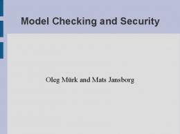
3. Hybrid Statecharts So far, we have used hybrid Finite State Machines (FSMs) to specify and verify a group of agents. Unfortunately, classical FSMs lack support for modularity, which is very important when modeling complex systems that contain similar subsystems. All states are equally visible and are considered to be at the same level of abstraction, which makes modeling cluttered and unreadable. In practice, to describe complex systems using FSMs, several extensions are useful. Statecharts have been introduced by Harel (1987) to overcome the limitations of traditional FSM. The most important extension is hierarchy, or what is called hierarchical (nested) FSM. Such a hierarchy has descriptive advantages over ordinary FSM in a sense that hierarchy of states offers a convenient structuring mechanism that allows us to specify systems with different levels of view. For their expressiveness, statecharts have become part of the Unified modeling language (UML) (UML, 2009). The main purpose of statecharts has been the description of complex reactive systems. However, in order to cope with those reactive systems that exhibit continuous timed behaviors, it seems to be advantageous to extend statecharts with continuous actions inside states. This extension allows complex/multi-agent systems to be modeled with different levels of abstraction and provides a formal way to analyze the dynamical behavior of the modeled systems. There are two possibilities of combination, namely combining statecharts with differential equations or extending hybrid automata with hierarchy. Therefore, both terms hierarchical hybrid automata (HHA) and hybrid statecharts can be used interchangeably. Basically, the straightforward way to analyze hierarchical machines is to flatten them and apply model checking tools on the resulting ordinary FSM. For example, Möller et al. (2003) have presented hierarchical specification of timed automata. In order to verify a hierarchical model, it has to be transformed first to flat timed automata, which in turn can be used as input for the model checker tool UPPAAL (Behrmann et al., 2004). Similarly, Ruh (2007) has presented a translator tool that automatically converts hybrid hierarchical statecharts, defined as an ASCII-formatted specification, into an input format for a model checker of simple hybrid automata (Henzinger et al., 1995a). In this section, we show, how hierarchical hybrid automata can be analyzed without getting involved in the flattening process. Let us come back to the illustrative RoboCup rescue scenario given in Sec. 2.1. Suppose that the specification of the fire brigade agent consists of the main control structure (FirebrigadeMain) and a rescue sub-system (FirebrigadeRSS) which are supposed to run in parallel. The latter just records the detected civilians. In addition to the fire brigade, the model should include a fire station, whose responsibility to inform and assign a fire brigade to a fire as soon as a fire alarm received. Now let us describe the scenario in a hierarchical way. At the top level is the rescue scenario, which in turn comprises at the lower level Fire, Civilians, Firestation, and Firebrigade. The latter can be described in a further lower level, which is FirebrigadeMain, and FirebrigadeRSS. The specification of this hierarchical structure is shown in Fig. 4. In the following, the hierarchical specification will be described in a formal flavor. 3.1 Formal Hierarchy
As illustrated by Fig. 4, for hierarchical hybrid automata (HHA), locations are generalized into a set Q of locations, which is partitioned into three disjoint sets: Qsimple , Qcomp , and Qconc — called simple, composite and concurrent locations. There is one designated start state, which is the topmost location in the hierarchy. In essence, the locations of plain hybrid automata correspond to simple location in the hybrid FSM. Composite and concurrent locations belong
/WNVK�4QDQV�5[UVGOU��/QFGNKPI��5RGEKſECVKQP��CPF�/QFGN�%JGEMKPI
���
Rescuescenario Fire no fire boom = 0 i: boom ≤ 3 ˙ =1 f: boom
boom = 3/neededw� = 120 burn
Civilians
injured w = 10 i: w ≥ 0 f: w˙ = −1
burning i: neededw > 0 ˙ =0 f: boom
neededw = 0
put out i: true ˙ =0 f: boom
help
w = 0/w� = 10
Firestation
assignFB
burn
idle i: true
i: false emergency reported
Firebrigade
FirebrigadeAgent
FirebrigadeAgent FirebrigadeMain
wLevel = wlMax ∧ neededw > 0 / refill m2ftime� = tSupply i: wLevel ≤ wlMax ˙ f: wLevel = rFill
m2stime = 0
move2supply i: m2stime ≥ 0 ˙ = −1 f: m2stime
wLevel = wlMax ∧neededw = 0 ∧civ = 0 idle i: true
wLevel = wlMax ∧ neededw = 0
emergency
reported
civ > 0/ civ� = civ − 1
wLevel = 0/m2stime� = tSupply FirebrigadeRSS
true /m2ftime� = 3
move2fire i: m2ftime ≥ 0 ˙ f: m2ftime = −1
neededw = 0 ∧ wLevel > 0
extinguish i: wLevel ≥ 0 ˙ f: wLevel = −rExt ˙ neededw = −rExt listen i: true
m2ftime = 0 help
true /civ� = civ + 1
Fig. 4. A hierarchical hybrid state machine for a RoboCup rescue scenario.
to the definition of statecharts (Harel, 1987) and have become part of UML (UML, 2009). They are useful for expressing the overall system on several levels of abstraction and multi-agent aspects, respectively. Events are treated as global variables in this context. Based on this, we will now introduce the concepts of HHA more formally (Furbach et al., 2008). Definition 3.1 (Hierarchy components). The basic components of HHA are the following disjoint sets:
���
4QDQV�5QEEGT
Q : a finite set of locations, which is partitioned into three disjoint sets: Qsimple , Qcomp , and Qconc — called simple, composite and concurrent locations, containing one designated start state q0 ∈ Qcomp ∪ Qconc . In the rescue example (Fig. 4), idle, extinguish or listen are simple locations, and FirebrigadeAgent is a concurrent location and FirebrigadeMain and FirebrigadeRSS are composite locations, which are separated by a dashed line. m2ftime and wLevel are examples for real valued variables. Definition 3.2 (Location hierarchy). Each location q is associated with zero, one or more initial locations α(q): a simple location has zero, a composite location exactly one, and a concurrent location more than one initial location. Moreover, each location q ∈ Q \ {q0 } is associated to exactly one superior state β(q). Therefore, it must hold β(q) ∈ Qconc ∪ Qcomp . A concurrent state must not directly contain other concurrent ones and all transitions (q1 , q2 ) must keep to the hierarchy, i. e. β(q1 ) = β(q2 ). For the example in Fig. 4, according to the previous Def. 3.2, it holds e.g.: α(Civilian) =injured. α(FirebrigadeAgent)={ FirebrigadeMain,FirebrigadeRSS}. α(Rescuescenario)={Fire,Civilian,Firestation,Firebrigade} β(burning) = Fire.
α(Firebrigade) = FirebrigadeAgent. α(Fire) = no_fire. α(Firestantion) = idle. β(Fire) = Rescuescenario.
The function β from the previous definition naturally induces a location tree with q0 as root. This is shown for the running example in Fig. 5. While processing, each composite location of the state machine contains only one active location. These locations also form a tree, called configuration. A configuration of the given state machine, is indicated by the thick lines in Fig. 5. Let us now define the notion configuration more formally. As shown in Def. 2.3, a hybrid automaton may change in two ways: discretely, from location q1 to another location q2 , when the transition e ∈ E between the two locations is enabled (i.e., the jump condition holds) and continuously within a control location q ∈ Q, by means of a finite (positive) time delay t. The semantics of our automata can now be defined by alternating sequences of discrete and continuous steps between configurations. Definition 3.3 (Semantics). The state machine starts with the initial configuration, i.e. the completed topmost initial state s0 of the overall state machine. In addition, an initial condition must be given as a predicate with free variables from X. The current situation of the whole system can be characterized by a triple (c, v, t) where c is a configuration, v a valuation (i. e. a mapping v : X → IRn ), and t the current time. The initial situation is a situation (c, v, t) where c is the initial configuration, v satisfies the initial condition, and t = 0. The following steps are possible in the situation (c, v, t): discrete step: a discrete/micro-step from one configuration c of a state machine to a configuration (c� , v� , t) by means of a transition (q, q� ) ∈ E with some jump condition in the current situation (written c → c� ) is possible iff: 1. c contains a node labeled with q; 2. the jump condition of the given transition holds in the current situation (c, v, t); 3. c� is identical with c except that q together with its sub tree in c is replaced by the completion of q� ; 4. the variables in X are set by executing specific assignments.
/WNVK�4QDQV�5[UVGOU��/QFGNKPI��5RGEKſECVKQP��CPF�/QFGN�%JGEMKPI
���
complete(T,Rest,State,[State:Var|Complete]) :init(T,State,[Var|Rest],Init,_), maplist(complete(T,[Var|Rest]),Init,Complete). discrete(T,Rest1,Rest2,[State1:Var1|_],[State2:Var2|Conf]) :trans(T,State1,[Var1|Rest1],State2,[Var2|Rest2]), complete(T,Rest2,State2,[State2:Var2|Conf]). discrete(T,Rest1,Rest2,[Top:Var1|Sub],[Top:Var2|Tree]) :Sub \= [], maplist(discrete(T,[Var1|Rest1],[Var2|Rest2]),Sub,Tree). continuous(T1,T2,Rest1,Rest2,[State:Var1|Sub],[State:Var2|Tree]) :flow(T1,T2,State,[Var1|Rest1],[Var2|Rest2]), maplist(continuous(T1,T2,[Var1|Rest1],[Var2|Rest2]),Sub,Tree).
Fig. 6. Code for the abstract state machine for HHA in CLP. The Rest variables host nested lists of the variables declared in the states superior to the current state. The built-in predicate maplist is a macro for applying a predicate call (first argument of maplist) to a list of arguments (second and third argument) one by one. continuous step: a continuous step/flow within the actual configuration to the situation (c, v� , t� ) requires the computation of all x ∈ X that are valid in c at the time t� according to the conjunction of all state conditions (i.e. flow conditions plus invariants) of the active locations q ∈ c, where it must hold t� > t. FirebrigadeAgent FirebrigadeMain
FirebrigadeRSS
idle move2fireextinguishmove2supply refill listen
Fig. 5. Location hierarchy and configuration tree (thick lines). Definition 3.4 (Configuration and Completion). A configuration c is a rooted tree of locations where the root node is the topmost initial location q0 of the overall state machine. Whenever a location q is an immediate predecessor of q� in c, it must hold β(q� ) = q. A configuration is completed by applying the following procedure recursively as long as possible to leaf nodes: if there is a leaf node in c labeled with a location q, then introduce all α(q) as immediate successors of q. 3.2 Hierarchy Implementation with CLP
In Sec. 2.5, a CLP implementation of concurrent hybrid automata was given which implements hybrid finite state machine. Now we will show how to implement an abstract state machine for HHA, treating hierarchies and concurrency more explicitly (Mohammed & Stolzenburg, 2008; 2009). This leads to a lean implementation of hybrid automata, where efficient CLP solvers are employed for performing complex analyses. Fig. 6 shows parts of the abstract state machine in Prolog, namely the code for completion and for performing discrete and continuous steps according to Def. 3.3 and 3.4. Discrete steps take zero time; continuous steps remain within the same configuration, but the variable values may differ. The flow conditions of active locations (in the configuration) must be applied, as
���
4QDQV�5QEEGT
time passes by. In this context, configurations are encoded in Prolog lists, where the head of a list corresponds to the root of the respective configuration tree. In addition, each location is conjoined by a colon (:) with its list of local variables. Thus, according to Def. 3.4, the completed start configuration will be represented as shown below. The use of lists is straightforward and allows us to implement the abstract state machine for HHA (see Fig. 6) within only a dozen lines of CLP/Prolog code. By this technique, explicit composition of automata is avoided. For each location, its initial states have to be declared together with their continuous flow conditions. For all discrete transitions, the jump conditions have to be stated. Local variables are expressed by nested lists of variables valid in the respective state. Since the abstract state machine is of constant size and the abstract machine computes complex configurations only on demand, there is a one-to-one correspondence between the elements of the HHA and its CLP/Prolog implementation. Thus, the program size is linear to the size of the HHA. In the concrete implementation of the rescue example, the overall start location q0 is indicated by the predicate start, while init defines the initial states for each state (α values according to Def. 3.2). The flow and the jump conditions have to be expressed by means of the predicates flow and trans. The reader can easily see from Fig. 7 that the size of the CLP program is only directly proportional to the size of the given HHA, because there is a one-to-one correspondence between the graphical specification and its encoding in Prolog, whereas computing the composition of concurrent automata explicitly leads to an exponential increase. Furthermore, since the overall system behavior is given by the abstract state machine (Fig. 6), this approach is completely declarative and concise. Similarly, in the CLP model of hybrid FSM, reachability analysis is performed by computing the state space of HHA under consideration starting from the initial configuration. For details as well as experiments on benchmarks, the reader is referred to (Mohammed & Stolzenburg, 2009).
4. A Tool: Automatic Design and Verification In the previous sections, we have shown a framework to specify and verify multi-agent system by means of hybrid automata. Traditionally, in order to verify a certain model with any hybrid automata model-checking tool, one has to specify such model textually with a suitable description language of a model checker. In our framework, one has to specify a multi-agent system in a constraint logic approach. However, in order to textually specify a certain scenario, generally two alternatives can be used: either designing a scenario prior to put it conveniently in a textual specification format to a model checker, or starting to specify the scenario directly with the suitable description languages, which is definitely a tedious and undesirable work, particularly when specifying safety critical systems. From this we may conclude, that it is favorable to graphically specify and automatically verify a certain scenario. For this, a combination of the graphical notations from software engineering with the formal methods realm is necessary. Generally, the graphical notation is becoming more and more accepted, as it is expected that designers will be more familiar with graphical notation. Therefore, several researchers have approached specifying the behaviors of multi-agent systems using graphical notations, namely UML statechart. For instance, Murray (2004) presents the statechart editor StatEdit that is used to graphically specify behaviors multi-agent systems with a layered structured. He has used StatEdit to design agents for the RoboCup simulation league. However, neither model checking, nor timed notation are allowed in the tool. In order to combine the formal
/WNVK�4QDQV�5[UVGOU��/QFGNKPI��5RGEKſECVKQP��CPF�/QFGN�%JGEMKPI
���
%%% rescue scenario start(rescuescenario). init(T,rescuescenario,[[Event]], [fire,civilians,firestation,firebrigade],_) :Event = none. flow(T1,T2,rescuescenario,[[Event]],[[Event]]). %%% fire init(T,fire,[[Boom,Neededw]|_],[no_fire],rescuescenario) :Boom $= 0. flow(T1,T2,fire,_,_). init(T,no_fire,[[]|_],[],fire). flow(T1,T2,no_fire,[[],[Boom1,Neededw]|_],[[],[Boom2,Neededw]|_]) :Boom2 $=< 3, Boom2 $>= Boom+(T2-T1). trans(T,no_fire,[[],[Boom,Neededw],[Event1]],burning,[[], [Boom,Neededw],[Event2]]) :Event2 = burn, Neededw $= 120.
Fig. 7. A part of the HHA implementation of the rescue example.
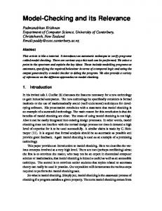
verification with graphical models, there already exist a number of tools proposed for validation of UML statecharts by translating models into the input language of existing model checkers. For example, Lilius & Porres (1999) have presented the tool vUML for model checking systems, which have been modeled by UML statecharts. They have used SPIN model checker (Holzmann, 1997) as the underlying verification engine in their tool. On the other hand, in order to graphically specify real time software using UML models, several researchers have extended the standard UML with time notation (Graf et al., 2006). For this purpose, several tools have been developed in order verify the timed UML models by mapping them to input languages of timed automata, which in turn are verified using existing timed automata model checkers. For example, (Del Bianco et al., 2002) have used Kronos (Yovine, 1997) as a model checker to verify their system, whereas (Knappi et al., 2002) have used UPPAAL (Behrmann et al., 2004) as a model checker for the purpose . Stemming from the previous discussion, we find that it seems advantageous to implement a tool (see Fig.8) that combines both design and verification in the same framework, instead of generating an intermediate specification, which in turn is given to a model checkers. To our knowledge, there is no tool that supports the integration of graphical notations and formal verification of hybrid automata with two different views of multi-agent systems, namely the concurrent and the hierarchical view. For this aim, the tool HieroMate (Mohammed & Schwarz, 2009) has been presented, which aims to simplify the process of specification and verification of MAS by combining the advantages of both graphical notations of software engineering together with formal methods. In the tool, the specification of MAS together with their requirements are graphically specified, then the process of verification is achieved automatically.
���
4QDQV�5QEEGT
Fig. 8. A tool for modeling and verification based on CLP.
A designer interacts with HieroMate using context sensitive menus that allows only meaningful actions. For example, the user is able to add a location to an automaton by right clicking onto the automaton and selecting Add location from a context menu. After a model has been built, the specification should be given for formal verification. Actually, a user can either specify queries manually using CLP Prolog, use the tool to generate simple queries automatically, or combine both methods. 4.1 Examples with Model checking
As we already mentioned, the formal semantics of our framework gives the possibility to apply formal methods in order to prove certain properties of specified systems, e.g. by model checking. However, in the context of hybrid automata the term model checking usually refers to reachability testing, i.e. the question whether some (unwanted) state is reachable from the initial configuration of the specified system. For this purpose, some exemplary model checking tasks for the rescue scenario can be investigated. For the behavior specification shown in Fig. 4 we conducted several experiments with HieroMate. The tool performs reachability tests on the state space of the model. This is done by first computing all reachable states from the initial state/configuration, and then checking the resulting set for the needed properties. In the following, we present some exemplary model checking tasks for the rescue scenario. Is it possible to extinguish the fire? When the state of the automaton modeling the fire changes from no fire to burning, the variable neededw stores the amount of water needed for putting out the fire (neededw = 120 in the beginning). When the fire is put out, i.e. neededw = 0, the automaton enters the state put out. Thus the fire can be extinguished, iff there is a reachable configuration cout where fire is in the state put out. It is easy to see from the specification, that this is indeed the case, as neededw is only decreased after the initial setting, and so the transition from burning to put out is eventually forced.
/WNVK�4QDQV�5[UVGOU��/QFGNKPI��5RGEKſECVKQP��CPF�/QFGN�%JGEMKPI
���
Does the agent try to extinguish with an empty water tank? To answer this question, we should check the reachability of certain intervals in the continuous valuation of the automaton. The fact that the fire brigade agent tries to put out the fire without water corresponds to the simple state extinguish being active while wLevel < 0. Note that we must not test for wLevel ≤ 0, as the state extinguish is only left when the water level is zero, so including a check for equality leads to false results. Won’t the fire brigade move to the fire if it is not burning? This is a kind of questions that needs to check the reachability of composed locations in the same time. This can be checked by investigating that no location where firebrigade is in location move2fire and fire is in location nofire, or putout is reachable Does the agent report all discovered civilians? We can check properties about the history of a certain state and the reachable states from a given state, this allows more complex questions like this question. Actually, this question contains two properties to be checked: (a) all discovered civilians are reported eventually, and (b) the agent does not report more civilians than it found. The property (a) corresponds to the fact that from every reachable state there is a state reachable where all discovered civilians have been reported. This again means that the number of transitions labeled with help equals the number of transitions labeled with reported. Property (b) holds if in the history of each reachable state the number of transitions labeled with help is always greater or equal to the number of transitions that are labeled with reported. All properties described above could be successfully proven using our framework.
5. Related Works Hybrid automata have not only been used in the context of robot soccer, but also in many other applications of multi-agent and multi-robot systems. Therefore, we will give a brief overview on related works on modeling, specification, and model checking such systems with focus on approaches that employ CLP. Using hybrid automata (Henzinger, 1996) is a well accepted method to model and analyze (mobile) multi-agent systems (Alur et al., 1999; 1996). Hierarchical hybrid automata (HHA) can be used for building up and describing multi-layer control architectures based on physical motion dynamics of moving agents (Borges de Sousa et al., 2007; Furbach et al., 2008). In many applications they form a link between multi-robot systems and theories of hybrid systems as in Zelinski et al. (2003). CLP as a programming paradigm has already been applied to modeling hybrid systems including solving differential equations (Hickey & Wittenberg, 2004b). Several authors propose the explicit composition of different concurrent automata by hand leading to one single automaton, before a CLP implementation is applied. This is a tedious work, especially when the number of automata increases. The latter case is exemplified in Urbina (1996) and Jaffar et al. (2004), where approaches to model and analyze hybrid systems using CLP(R) (Jaffar et al., 1992) are introduced. In Banda & Gallagher (2008), it is shown how reachability analysis for linear hybrid automata can be done by means of CLP, again by computing compositions of (simple) hybrid automata. Events are handled as constraints, which avoids some of the effort for computing composition, which leads to an exponential increase in the number of clauses in general. In our approach, however, we compute configurations of the overall system only if required.
���
4QDQV�5QEEGT
In contrast to our approach, some authors approached modeling the behavior of hybrid systems as an automaton using CLP, but they do not handle a hybrid system consisting of different interacting hybrid automata. For example, Hickey & Wittenberg (2004a) present a hybrid system modeled as an automaton using CLP(F) (Hickey & Wittenberg, 2004b), but neither handling concurrency nor hierarchies. Other authors employ CLP for implementing hybrid automata (Ciarlini & Frühwirth, 2000; Delzanno & Podelski, 1999; Gupta & Pontelli, 1997), but restrict attention to a simple class of hybrid systems (e.g. timed systems). They do not construct the overall behavior prior to modeling, but model each automaton separately. However, the run of the model takes all possible paths into consideration, resulting from the product of each component, which leads to unnecessary computation. Another interesting approach on model checking hybrid systems is presented in Gulwani & Tiwari (2008). There, an analysis technique is proposed that is able to derive verification conditions, i.e. constraints that hold in reachable states. These conditions are universally quantified and transformed into purely existentially quantified conditions, which is more suitable for constraint solving. For this, an implementation in Lisp is available employing a satisfiability modulo theories (SMT) solver, whereas the Prolog implementation presented in this chapter, allows to express discrete transitions explicitly and allows the use of several constraint solvers. Another approach for verification of hybrid systems is presented in Fränzle & Herde (2007). In particular, the authors apply so-called bounded model checking (BMC) (Biere et al., 1999) to linear hybrid automata, by encoding them into predicative formulae suitable for BMC. For this reason, they developed a tool called HySAT that combines a SAT solver with linear programming, where the Boolean variables are used for encoding the discrete components, while real variables represent the continuous component. The linear programming routine is used to solve large conjunctive systems of linear inequalities over reals, whereas the SAT solver is used to handle disjunctions. Similar to this approach, our approach presented in this chapter has the essence of BMC. However, instead of checking the satisfiability of formulae to some given finite depth k, we find the set of reachable states and verify various properties on this set. In Biere et al. (1999), neither concurrency nor hierarchy of hybrid automata is taken into consideration. Differently to this chapter, Jha et al. (2007) introduce symbolic reachability analysis of lazy linear hybrid automata. They provide a verification technique based on bounded model checking and k-induction for reachability analysis. In their technique, SAT-based decision procedures are used to perform a symbolic analysis instead of an enumerative analysis. However, they did not show how the interacting concurrent components can be handled in their approach.
6. Conclusion In this chapter, we have shown a framework to formally specify and verify physical multiagent systems by means of hybrid automata, especially for those agents that are defined through their capability to continuously react to a physical environment, while respecting some time constraints. The framework provided two different views of behaviors’ specifications, namely, the concurrent and the hierarchical view. In the concurrent view, it has been demonstrated how to avoid the composition of the agents before getting involved into the verification phase,which, in turn can relieve the state explosion problem that may raise as the result of specifying multi-agent systems. On the other hand, in the hierarchical view, we show how multi-agent systems can be hierarchically specified and formally verified without flattening the hierarchy, as it is commonly done. We have shown the implementations of both views
/WNVK�4QDQV�5[UVGOU��/QFGNKPI��5RGEKſECVKQP��CPF�/QFGN�%JGEMKPI
���
by means of constraint logic programming, which forms the specification and the verification engine of the framework. In addition, we have presented a tool that graphically specifies both views, in order to combine the powerful of software engineering into our framework. A case study taken from RoboCup rescue simulation has been depicted to show applicability of our approach.
7. References Alur, R. & Dill, D. (1994). A Theory of Timed Automata, Theoretical Computer Science 126(2): 183–235. Alur, R., Esposito, J. M., Kim, M., Kumar, V. & Lee, I. (1999). Formal modeling and analysis of hybrid systems: A case study in multi-robot coordination, World Congress on Formal Methods, pp. 212–232. URL: citeseer.ist.psu.edu/article/alur99formal.html Alur, R., Henzinger, T. A. & Ho, P.-H. (1996). Automatic symbolic verification of embedded systems., IEEE Transactions on Software Engineering 22(3): 181–201. Apt, K. R. & Wallace, M. (2007). Constraint Logic Programming Using Eclipse, Cambridge University Press, Cambridge, UK. Arai, T. & Stolzenburg, F. (2002). Multiagent systems specification by uml statecharts aiming at intelligent manufacturing, AAMAS ’02: Proceedings of the first international joint conference on Autonomous agents and multiagent systems, ACM, New York, NY, USA, pp. 11–18. Banda, G. & Gallagher, J. P. (2008). Analysis of linear hybrid systems in CLP, in M. Hanus (ed.), Pre-Proceedings of LOPSTR 2008 – 18th International Symposium on Logic-Based Program Synthesis and Transformation, Technical University of Valencia, Spain, pp. 58–72. Behrmann, G., David, A. & Larsen, K. G. (2004). A tutorial on Uppaal, in M. Bernardo & F. Corradini (eds), Proceedings of 4th International School on Formal Methods for the Design of Computer, Communication, and Software Systems – Formal Methods for the Design of Real-Time Systems (SFM-RT), LNCS 3185, Springer, Berlin, Heidelberg, New York, pp. 200–236. Biere, A., Cimatti, A., Clarke, E. M. & Zhu, Y. (1999). Symbolic model checking without BDDs, Proceedings of 5th International Conference on Tools and Algorithms for Construction and Analysis of Systems (TACAS), LNCS 1579, Springer, Berlin, Heidelberg, New York, pp. 193–207. Borges de Sousa, J., Johansson, K. H., Silva, J. & Speranzon, A. (2007). A verified hierarchical control architecture for coordinated multi-vehicle operations, International Journal of Adaptive Control and Signal Processing 21(2-3): 159–188. Special issue on autonomous adaptive control of vehicles. Ciarlini, A. & Frühwirth, T. (2000). Automatic derivation of meaningful experiments for hybrid systems, Proceeding of ACM SIGSIM Conf. on Artificial Intelligence, Simulation, and Planning (AIS’00) . Clarke, E., Grumberg, O. & Peled, D. (1999). Model checking, Springer. da Silva, V., Choren, R. & de Lucena, C. (2004). A UML Based Approach for Modeling and Implementing Multi-Agent Systems, Proceedings of the Third International Joint Conference on Autonomous Agents and Multiagent Systems-Volume 2, IEEE Computer Society Washington, DC, USA, pp. 914–921. Del Bianco, V., Lavazza, L. & Mauri, M. (2002). Model checking uml specifications of real time software, p. 203.
���
4QDQV�5QEEGT
Delzanno, G. & Podelski, A. (1999). Model checking in CLP, Proceedings of 5th International Conference on Tools and Algorithms for Construction and Analysis of Systems (TACAS), LNCS 1579, Springer, Berlin, Heidelberg, New York, pp. 223–239. Egerstedt, M. (2000). Behavior Based Robotics Using Hybrid Automata, Proceedings of the Third International Workshop on Hybrid Systems: Computation and Control, Springer, pp. 103– 116. Fränzle, M. & Herde, C. (2007). HySAT: An efficient proof engine for bounded model checking of hybrid systems, Formal Methods in System Design 30(3): 179–198. Frehse, G. (2005). PHAVer: Algorithmic verification of hybrid systems past HyTech, in M. Morari & L. Thiele (eds), Hybrid Systems: Computation and Control, 8th International Workshop, Proceedings, LNCS 3414, Springer, Berlin, Heidelberg, New York, pp. 258– 273. Furbach, U., Murray, J., Schmidsberger, F. & Stolzenburg, F. (2008). Hybrid multiagent systems with timed synchronization – specification and model checking, in M. Dastani, A. El Fallah Seghrouchni, A. Ricci & M. Winikoff (eds), Post-Proceedings of 5th International Workshop on Programming Multi-Agent Systems at 6th International Joint Conference on Autonomous Agents & Multi-Agent Systems, LNAI 4908, Springer, pp. 205–220. Graf, S., Ober, I. & Ober, I. (2006). A real-time profile for UML, International Journal on Software Tools for Technology Transfer (STTT) 8(2): 113–127. Gulwani, S. & Tiwari, A. (2008). Constraint-based approach for analysis of hybrid systems, in J.-F. Raskin & P. S. Thiagarajan (eds), Proceedings of 20th International Conference on Computer Aided Verification (CAV 2008), LNCS 5123, Springer, Berlin, Heidelberg, New York, Princeton, NJ, pp. 190–203. Gupta, G. & Pontelli, E. (1997). A constraint-based approach for specification and verification of real-time systems, Proceedings of IEEE Real-time Symposium pp. 230–239. Harel, D. (1987). Statecharts: A visual formalism for complex systems, Science of Computer Programming 8: 231–274. Henzinger, T. (1996). The theory of hybrid automata, Proceedings of the 11th Annual Symposium on Logic in Computer Science, IEEE Computer Society Press, New Brunswick, NJ, pp. 278–292. Henzinger, T. A., Ho, P.-H. & Wong-Toi, H. (1995a). HyTech: The Next Generation, IEEE Real-Time Systems Symposium, pp. 56–65. Henzinger, T., Ho, P.-H. & Wong-Toi, H. (1995b). A user guide to HyTech, Proceedings of International Conference on Tools and Algorithms for the Construction and Analysis of Systems (TACAS), LNCS 1019, Springer, Berlin, Heidelberg, New York, pp. 41–71. Henzinger, T., Kopke, P., Puri, A. & Varaiya, P. (1998). What’s Decidable about Hybrid Automata?, Journal of Computer and System Sciences 57(1): 94–124. Hickey, T. J. & Wittenberg, D. K. (2004a). Rigorous modeling of hybrid systems using interval arithmetic constraints, in R. Alur & G. J. Pappas (eds), Proceedings of 7th International Workshop on Hybrid Systems: Computation and Control (HSCC 2004), LNCS 2993, Springer, Berlin Heidelberg, New York, Philadelphia, PA, USA, pp. 402–416. Hickey, T. J. & Wittenberg, D. K. (2004b). Using analytic CLP to model and analyze hybrid systems, in V. Barr & Z. Markov (eds), Proceedings of the 17th International Florida Artificial Intelligence Research Society Conference, AAAI Press. Holzmann, G. (1997). The model checker SPIN, IEEE Transactions on software engineering 23(5): 279–295.
/WNVK�4QDQV�5[UVGOU��/QFGNKPI��5RGEKſECVKQP��CPF�/QFGN�%JGEMKPI
���
Jaffar, J. & Lassez, J. (1987). Constraint logic programming, Proceedings of the 14th ACM SIGACT-SIGPLAN symposium on Principles of programming languages, ACM New York, NY, USA, pp. 111–119. Jaffar, J., Michaylov, S., Stuckey, P. & Yap, R. (1992). The CLP(R) language and system, ACM Transactions on Programming Languages and Systems 14(3): 339–395. Jaffar, J., Santosa, A. & Voicu, R. (2004). A clp proof method for timed automata, Real-Time Systems Symposium, IEEE International 0: 175–186. Jha, S., Brady, B. A. & Seshia, S. A. (2007). Symbolic reachability analysis of lazy linear hybrid automata, in J.-F. Raskin & P. S. Thiagarajan (eds), Proceedings of 5th International Conference on Formal Modeling and Analysis of Timed Systems (FORMATS 2007), LNCS 4763, Springer, Berlin, Heidelberg, New York, Salzburg, Austria, pp. 241–256. Knappi, A., Merzi, S. & Rauh, C. (2002). Model Checking Timed UML State Machines and Collaborations, Proceedings of the 7th International Symposium on Formal Techniques in Real-Time and Fault-Tolerant Systems: Co-sponsored by IFIP WG 2.2, Springer, p. 395. Lilius, J. & Porres, I. (1999). Formalising UML state machines for model checking, The Unified Modeling Language: UML’99: Beyond the Standard: Second International Workshop, Fort Collins, Springer, p. 430. Mohammed, A. & Furbach, U. (2008a). Modeling multi-agent logistic process system using hybrid automata, Modelling, Simulation, Verification and Validation of Enterprise Information Systems, Proceedings of the 6th International Workshop on Modelling, Simulation, Verification and Validation of Enterprise Information Systems, MSVVEIS-2008, INSTICC PRESS, pp. 141–149. Mohammed, A. & Furbach, U. (2008b). Using CLP to model hybrid systems, Proceedings of Annual ERCIM Workshop on Constraint Solving Programming (CSCLP2008). URL: http://pst.istc.cnr.it/CSCLP08/program Mohammed, A. & Furbach, U. (2009). Multi-agent systems: Modeling and verification using hybrid automata, Proceedings of the 7th International Workshop on Programming MultiAgent Systems (ProMAS 2009), May 10-15, 2009, Budapest, Hungary. Extended version available as Technical Report 8/2009, Department of Computer Sceince,University of Koblenz-landau. Mohammed, A. & Schwarz, C. (2009). HieroMate: A graphical tool for specification and verification of hierarchical hybrid automata, in B. Mertsching, M. Hund & Z. Aziz (eds), KI 2009: Advances in Artificial Intelligence, Proceedings of 32nd Annual German Conference on Artificial Intelligence, LNAI 5803, Springer, Berlin, Heidelberg, New York, Paderborn, pp. 695–702. Mohammed, A. & Stolzenburg, F. (2008). Implementing hierarchical hybrid automata using constraint logic programming, in S. Schwarz (ed.), Proceedings of 22nd Workshop on (Constraint) Logic Programming, University Halle Wittenberg, Institute of Computer Science, Dresden, pp. 60–71. Technical Report 2008/08. Mohammed, A. & Stolzenburg, F. (2009). Using constraint logic programming for modeling and verifying hierarchical hybrid automata, Technical Report 6/2009, Department of Computer Science, Universität Koblenz–Landau. Möller, O., David, A. & Yi, W. (2003). Verification of uml statechart with real-time extensions, Fundamental Approaches to Software Engineering (FASE’2002), LNCS 2306, SpringerVerlag, pp. 218–232.
���
4QDQV�5QEEGT