12â14 September 2017, ULB-VUB, Brussels, Belgium ... fly ash to mitigate the risks of chloride attack and ASR, anti-corrosion rebar, and 6% entrained air for frost damage1. It .... C : Ordinary portland cement, FA : Fly ash, EX : Expansive Agent .... train. (micro. ) Material Age (days). Material Age (days). Sun-exposed.
2nd International RILEM/COST Conference on Early Age Cracking and Serviceability in Cement-based Materials and Structures - EAC2 12–14 September 2017, ULB-VUB, Brussels, Belgium
Multi-scale and multi-chemo-physical modeling of cementitious composite and its application to early age crack assessment of reinforced concrete slab decks Tetsuya ISHIDA*a, Ichiro IWAKI*b a Department of Civil Engineering, The University of Tokyo, Tokyo, Japan b College of Engineering, Nihon University, Koriyama, Japan ABSTRACT This paper presents numerical simulation of early age deformation and cracking of RC structures with full 3D multi-scale and multi-physical integrated analysis. First, a multi-scale constitutive model of solidifying cementitious materials is briefly introduced based on systematic knowledge coupling microscopic thermodynamic phenomena and microscopic structural mechanics. Then, model validations are done by applying the multi-scale and multi-physical integrated analysis system to the early-age behavior of small sized specimens, full-size RC deck slab specimens, and real RC slab decks to be constructed. Through experimental validation and full-scale numerical simulation, factors affecting cracking generation and propagation are identified. Keywords: Select up to 5 keywords, separated by comma
1. INTRODUCTION Much of Japan’s infrastructure was constructed during the last half century, and parts of this infrastructure are undergoing severe deterioration due to environmental and loading actions. Among them, road structures in cold and snowy region are reported to show faster and severer deterioration than expected due to combined frost damage, chloride attack from deicing agent, ASR, cracking, fatigue, and so on. For such structures, it is necessary to assure durability performance in design considering conceivable environmental and loading actions during service. In November 2011, the Japanese government resolved to build “the Revival Roads” in the Tohoku region to accelerate recovery from the Great East Japan Earthquake of March 2011. Since the Tohoku region experiences cold and snowy weather in the winter, complex degradation involving multiple factors such as those mentioned above is anticipated. Thus, in order to enhance the durability performance of road structures, more particularly RC slab decks, the authors propose multiple countermeasures: low water-to-cement ratio in the mix, use of mineral admixtures such as blast furnace slag and/or fly ash to mitigate the risks of chloride attack and ASR, anti-corrosion rebar, and 6% entrained air for frost damage 1. It should be noted here that such a high durability specification may conversely increase the risk of early age cracking caused by temperature and shrinkage due to the large amount of cement and the use of mineral admixtures. Against this background, this paper presents numerical simulation of early age deformation and cracking of RC structures with full 3D multi-scale and multi-physical integrated analysis. First, a multi-scale constitutive model of solidifying cementitious materials is briefly introduced based on systematic knowledge coupling microscopic thermodynamic phenomena and microscopic structural mechanics. Then, model validations are done by applying the multi-scale and multiphysical integrated analysis system to the early-age behavior of small sized specimens, full-size RC deck slab specimens, and real RC slab decks to be constructed. Through experimental validation and full-scale numerical simulation, factors affecting cracking generation and propagation are identified.
2. OVERVIEW OF MULTI-SCALE AND MULTI-PHYSICAL MODELING In order to achieve the rational design, construction, and maintenance of concrete structures, it is important to predict the performance of structures over their lifespan, from the start of the hydration reaction until the end of their service life, considering various material and mix proportions, structural dimensions, and curing and environmental conditions. Aiming for a unified approach to the evaluation of the behavior of concrete structures under any of various conditions, the Concrete Laboratory of the University of Tokyo has been working to develop a multi-scale integrated analysis platform, DuCOMCOM32. The platform consists of two systems: a thermodynamic coupled analysis system, DuCOM, which integrates
2nd International RILEM/COST Conference on Early Age Cracking and Serviceability in Cement-based Materials and Structures - EAC2 12–14 September 2017, ULB-VUB, Brussels, Belgium
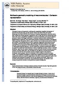
various micro-physical-chemical based models of cementitious composites, and a non-linear dynamic RC structure analysis system COM3, which deals with macroscopic mechanical response and damage of reinforced concrete structures. Figure 1 gives an overview of the multi-scale and multi-physical modelling to simulate time-dependent deformation and cracking of concrete structures. In the multi-scale constitutive model, concrete is idealized as a two-phase composite that consists of cement paste and elastic aggregate suspended inside (Fig.1, B) 2. Aggregate is assumed to be rigid and show elastic deformation, and the shrinkage caused by aggregates is also taken into account. The hardened cement paste matrix is assumed as an assembly of fictitious clusters referring to the solidification theory. As cement hydration proceeds, the number of clusters increases. The overall capacity of a cement matrix is obtained by summing the capacities of all the clusters, which show time-dependent deformation relevant to the history. The time-dependent deformation consists of elastic, visco-elastic, visco-plastic and plastic components, which are simulated based on the water status in micro-pores. During the drying process, water in pores is lost gradually. Accordingly, in micro-scale pores, a water meniscus forms and some shrinkage stress is generated by capillary tension. Besides, in nano-scale pores, shrinkage stress is generated by disjoining pressure. These shrinkage stresses are quantified in the multi-scale model and integrated as the overall shrinkage stresses as shown in Fig.1, A3, which are given to compute volumetric stress of cement paste carried by both skeleton solid and pore pressure, referring to Biot’s theorem of two phase continuum4. The volumetric change caused by cement hydration and shrinkage is systematically included in the modelling of concrete mechanics, which deals with structure responses based on the space averaged constitutive laws on the fixed four way cracked concrete model (Fig.1, D). Here it should be noted that the cracking critera shall be set based on the local tensile strength depending on the moisture state inside concrete, since drying has both negative and positive effects: micro-cracks caused by drying reduce tensile strength, while negative pore water pressure in a dry state works as pre-stress and enhances local resistance against tensile load5. Thus, in the model, different local tensile strengths were taken into account according to the moisture status in micro and nano-pores (Fig.1, C). A
Time-dependent mechanics B ( Solidification model)
Shrinkage Driving Force Model Disjoining Pressure
Gel particle
Capillary Tension
Hydration product
Unhydrated part
Cement particle Interlayer pore (2.8Å) |
10-10
|
10-9
Micro-Fracture Model
Gel pore Capillary pore |
10-8
C
|
|
10-7
10-6
|
10-5
|
|
|
10-4
10-3
10-2
Smeared Crack Model |
10-1
|
|
100
101
(m) D
Micro-Fracture Model
Smeared Crack Model
Figure 1: Multi-scale and multi-physical modelling to simulate time-dependent deformation and cracking
2nd International RILEM/COST Conference on Early Age Cracking and Serviceability in Cement-based Materials and Structures - EAC2 12–14 September 2017, ULB-VUB, Brussels, Belgium
3. NUMERICAL SIMULATION OF EARLY AGE BEHAVIOR OF SMALL SPECIMENS AND FULL SIZE RC DECK SLABS 3.1 Target of analysis Durability of concrete is a common engineering concern all over the world. In Japan, concrete structures, and more particularly RC deck slabs of road bridges, in cold and snowy regions such as the Tohoku region in northeast Japan, undergo complex degradation as the result of combined frost damage and chloride attack caused by de-icing agent, degradation due to alkali-silica reaction (ASR), and fatigue under traffic loading. Thus, many concrete structures need repair or reconstruction due to serious damage caused by severe environmental actions and external loads. In a bid to address these issues, the authors are currently involved in a project to study countermeasures for such complex degradation of road infrastructures, which was launched as a collaborative initiative between academia and industry supported by the Cabinet Office of the government of Japan (cross-ministerial Strategic Innovation Program, SIP). In this project, a comprehensive experimental study and performance assessment with multi-scale integrated analysis are being conducted to enhance durability of road infrastructures under harsh environmental conditions. This paper mainly focuses on the early age deformation and cracking of concrete structures, although the project itself covers various long-term durability issues of concrete structures, such as chloride penetration, rebar corrosion, ASR, and frost damage, fatigue under repeated load 1. In order to study free volumetric change, deformational behavior and initial defects (cracking) under restraint conditions due to shrinkage, three series of specimens using different materials and curing conditions were created, producing 200 × 200 × 800 mm prism-shaped specimens, φ100 × 200 mm cylindrical specimens, and full-size RC deck slabs with main steel girders. Since mix proportions and curing conditions strongly affect shrinkage induced cracking, the water-to-binder ratio and curing period were varied in the test (Table 1). In addition, as a countermeasure for ASR and chloride attack, concrete with fly ash was tested, and in some specimens, expansive agent was also used to mitigate the risk of harmful cracks. Each specimen was placed in a real environment year round, and the impact of environmental conditions including temperature, humidity, solar radiation, and rainfall was studied. Table 1 Mix proportions of concrete and curing conditions Unit content (kg/m2) C FA EX S
Series
W/B (%)
Air (%)
W
No.1
55
4.5
172
313
―
―
834
997
7days sealed curing
No.2
45
6.0
161
338
―
20
791
992
7days sealed curing
No.3
45
G
Curing period
6.0 161 338 72 20 709 992 91days sealed curing C : Ordinary portland cement, FA : Fly ash, EX : Expansive Agent
3.2 Simulation of small sized specimens As shown in Figure 2, considering the asymmetric nature of the top and bottom surfaces on account of rainfall, a 1/4 scale model consisting of 200 × 200 × 800 mm prism-shaped specimens was used. Taking into account the symmetric boundary restraints and specimen placement condition, vertical restraint was input at the bottom surface of the specimens. As input, mix proportions, casting temperature, and curing conditions were identically given according to the actual experimental conditions. The environmental conditions given as input in the analysis are shown in Figure 2. The sun-exposed, shade, and indoor temperature and humidity values were obtained by using temperature and humidity data loggers at each location. Rainfall is an important environmental factor that influences concrete shrinkage strain. As a method to represent the water absorption of concrete due to rainfall in a simplified manner, the emissivity coefficient in the surface mass flux is assumed to be 100 times the original value ((=5.0×10⁻⁵(m/s)), although the actual hydraulic pressure acting on the exposed surface
Figure 2: FE Mesh of small specimen
Figure 3: Environmental conditions
can be given in the model6. Figure 3 shows the rainfall numbers for Koriyama in Fukushima Prefecture, measured at tenminute intervals, obtained from the Japan Meteorological Agency. In line with the rainfall data, ten minutes was used as the analysis step interval for rainfall. Figures 4 to 6 show the actual measurement values and the analysis values for small specimens. As shown in Figures 4 and 5, compressive strength development and mass loss under various conditions are well simulated by the model. Figure 6 shows strain of concrete with time. Regarding the analysis of the No. 1 and No. 2 series, which do not use expansive agent, expansion due to water absorption from rainfall (in the case of specimens stored in the sun) was underestimated. Thus, the authors understand that the simplified method to reproduce the rainfall effect should be improved to enhance the accuracy of numerical prediction, although in the case of a larger cross section, such as a full-size RC slab, this effect would be relatively small. Moreover, while the analysis values generally approximate the measured values of the specimens stored indoors for No. 1 and No. 2, a slight difference can be seen for the specimens stored in the shade. It is considered that unlike the specimens stored indoors, the specimens stored in the shade were subjected to influences such as the wind, resulting in some difference between the analysis values and the measured values. In the case of No. 3, the numerical model approximately reproduces measured strain for each environmental condition, while in the case of No. 4, the amount of shrinkage, particularly in the case of sealed curing for 91 days, is seen to have been overestimated. Since the No. 4 specimen uses FA, it is inferred that this is due to overestimation of the hydration reaction of FA in the analysis, which lead to overestimation of autogenous shrinkage during sealed curing. For the time being, the authors opt to validate and update the pozzolanic reaction model of FA, and will examine this issue in the future.
0.0 -1.0
7封かん7日 days sealed curing
-3.0 0
50
-2.0
-3.0 100 150 200 0
Material (日) (days) 材齢Age
0.0 -1.0
7 days sealed curing 封かん7日
50
80
シリーズNo.4 Series No.3
-2.0
-3.0 100 150 200 0
Material Age (日)(days) 材齢
91 days sealed curing 封かん91日
50
100 150 200
40
No.1 (Cal.) No.2 (Cal.) No.3 (Cal.)
20
0 50
100
150
200
材齢 (日) Material Age (days)
Figure 5: Compressive strength development
ひずみ量 (μ)
ひずみ量 (μ)
600 600 600 600 日陰保管 日向保管 室内保管 Sun-exposed Shaded Indoor 400 400 400 400 封かん7日 7days sealed 封かん7日 7days封かん7日 sealed 200 7days sealed 200 200 200 curing curing curing 0 0 0 0 Shaded Sun-exposed -200 -200 -200 -200 7days sealed 7days sealed 日陰保管 日向保管 -400 -400 -400 -400 curing curing 封かん7日 封かん7日 -600 -600 -600 -600 50 100 150 200 0 0 50 100 150 200 0 50 100 150 200 0 50 100 150 200 0 50 100 150 200 Material Age (days) Material Age (days) Material Age (days) Material Material Age (days) 材齢 (日) 材齢 (日) 材齢 (日) 材齢 Age (日) (days) 材齢 (日) ひずみ量 (μ)
ひずみ量 (μ) Strain (micro)
600 400 200 0 -200 -400 -600
日向解析 No.1 (Exp.) No.2 (Exp.) No.3 (Exp.)
60
0
Material Age(日) (days) 材齢
Figure 4: Measured and computed mass loss of each series 600 400 200 0 -200 -400 -600
日陰解析
(a) No.1 Series (W/C 55%)
ひずみ量 (μ)
ひずみ量 (μ)
600 600 400 400 200 200 0 0 Sun-exposed -200 -200 Shaded 91 days Indoor 91days 日向保管 日陰保管 室内保管 91 days sealed -400 -400 sealed curing sealed curing 封かん91日 curing 封かん91日 封かん91日 -600 -600 50 100 150 200 50 100 150 200 0 0 50 100 150 200 0 Material Age (days) Material Age (days) Material 材齢 Age (日) (days) 材齢 (日) 材齢 (日)
ひずみ量 (μ)
-2.0
0.0 -1.0
室内解析
Compressive
質量変化量 (kg) Mass loss(kg)
1.0
Shaded (Analysis) 日陰解析 2.0 シリーズNo.3 Series No.2 1.0 質量変化量 (kg)
Indoor (Analysis) 室内解析 2.0 シリーズNo.1 Series No.1 1.0
2.0
質量変化量 (kg)
日向実測
Sun-exposed 日向実測 (Measurement) Sun-exposed 日向解析 (Analysis)
Shaded (Measurement) 日陰実測
(MPa) strength(MPa) 圧縮強度
Indoor (Measurement) 室内実測
ひずみ量 (μ) Strain (micro)
陰実測
2nd International RILEM/COST Conference on Early Age Cracking and Serviceability in Cement-based Materials and Structures - EAC2 12–14 September 2017, ULB-VUB, Brussels, Belgium
(b) No.2 Series (W/B 45%)
Black lines: Analysis Colored lines: Experiment
(c) No.3 Series (W/B 45%) Figure 6: Measured and computed concrete strain of each series 3.3 Application of the analysis model to full-size RC deck slab specimens A 1/2 model of an RC deck slab specimen including restraint by a main steel girder was used in the analysis (Figure 7). The main steel girder and RC deck slab form a rigid connection by sharing the finite element nodes. Figure 8 shows the deck slab reinforcement diagram. D19 rebar is used for the main reinforcement, and D16 rebar for the distribution bars. In
2nd International RILEM/COST Conference on Early Age Cracking and Serviceability in Cement-based Materials and Structures - EAC2 12–14 September 2017, ULB-VUB, Brussels, Belgium
accordance with the reinforcement diagram, for the analysis elements, RC elements are inserted in layers (right figure in Figure 8), and the other parts consist of plain concrete elements. The environmental conditions of the small specimens stored in the sun were input for the top surface of the RC deck slab, and the environmental conditions (Figure 3) for the small specimens stored in the shade were input for the other surfaces. To take into account the expansion and contraction behaviour of the main steel girders caused by temperature variation, the outside air temperature was also given as a boundary condition for the main steel girders. The effect of rainfall was set in the same way as for the small specimens. Further, as all the series are demolded at 7 days, in the analysis, their self-weight was set to apply from day 7.
0 1 2 3 4 5 6 7 材齢Age (日)(days) Material
0
50
100 150 200
0
材齢 Age (日) (days) Material
50
0
50
100 150 200
材齢Age (日)(days) Material
600 400 200 0 -200 -400 -600
封かん7日 7days sealed curing Deck slab床版中央 center
0
50
100 150 200
材齢Age (日)(days) Material
100 150 200
封かん7日 7days sealed curing Deck slab床版中央 center
0
50
100 150 200
Material 材齢Age (日) (days)
(a) No.1 Series (W/C 55%)
ひずみ量 (μ) (micro) Strain
Strain (micro)
ひずみ量 (μ)
ひずみ量 (μ) (micro) Strain
封かん7日 7days sealed curing On haunchハンチ上
600 400 200 0 -200 -400 -600
Material 材齢Age (日)(days)
Figure 9: Temperature history in a RC slab deck (Black lines: Analysis, Colored lines: Measured) 600 400 200 0 -200 -400 -600
ひずみ量 (μ)
封かん7日 7days sealed curing On haunchハンチ上
Strain (micro)
No.1 Deck slab center 床版中央
600 400 200 0 -200 -400 -600
600 400 200 0 -200 -400 -600
封かん91日 91days sealed curing On haunch ハンチ上
0
50
100 150 200
材齢Age (日)(days) Material
(b) No.2 Series (W/B 45%)
ひずみ量 (μ) Strain (micro)
No.1 No.1 Deck slab center 床版中央
40 30 20 10 0 -10
Figure8: Reinforce diagram and element layout of RC deck slab
ひずみ量 (μ) (micro) Strain
40 30 20 10 0 -10
温度 (℃) ( ̊C) Temperature
温度 (℃) Temperature ( ̊C)
Figure 7: FE Mesh of RC deck slab
600 400 200 0 -200 -400 -600
封かん91日 91days sealed curing 床版中央 Deck slab center
0
50
100 150 200
Material 材齢Age (日)(days)
(c) No.3 Series (W/B 45%)
Figure 10: Measured and computed concrete strain in the bridge axis direction (Black lines: analysis, Colored lines: Measured) Figure 9 shows the temperature measurement results from the embedded gauge in the center of the No. 1 series deck slab and the analysis results. By inputting the constituent materials and environmental conditions, the analysis model was shown to satisfactorily approximate the measured values for both the rise in temperature due to early-age hydration heat generation (Figure 9, left) and the long-term temperature history (Figure 9, right). Next, Figure 10 shows the strain in the bridge axis direction at the center of the cross section of the deck slab. For No. 2 and No. 3 using expansive admixture (Figure 10 (b)(c)), free expansion of 200 μ for No. 2 and 300 μ for No. 3 was input for analysis to make the early-age expansion caused by the expansive admixture match the measured values. Looking at the results, similarly to the analysis results for strain in the small specimens, for No. 1 and No. 2 (Figure 10), the analysis largely approximated the measured values. On the other hand, for No. 3 (Figure 10 (c)), divergence with the measured values was observed, similarly to the small specimens. All the series showed a similar trend to that of the small specimens, and it was confirmed that if the analysis model is able to approximate various behaviors of small specimens, then it is also able to approximate the behavior of RC deck slabs that resemble actual structures. However, with regard to the influence of rebar restraints on the effect of expansive admixture (chemical press-stress, etc.), more detailed investigation is required. 3.4 Cracking assessment of real RC slab deck in Tohoku region As a final example, cracking assessment of the Shinkesen Bridge, which is a seven span steel girder bridge with RC slabs, is presented. In November 2011, the Japanese government resolved to build “the Revival Roads” to accelerate recovery from the Great East Japan Earthquake of March 2011. The reconstruction road is located along the Sanriku coast devastated
2nd International RILEM/COST Conference on Early Age Cracking and Serviceability in Cement-based Materials and Structures - EAC2 12–14 September 2017, ULB-VUB, Brussels, Belgium
by the tsunami that accompanied the earthquake. The Shinkesen Bridge will be constructed as a part of the Revival Roads, and its RC deck slabs will be cast in June 2016. Since the Tohoku region where the Shinkesen Bridge will be in service experiences cold and snowy weather, complex degradation is anticipated due to combined frost damage, chloride attack from de-icing salt, ASR and fatigue. Thus, in order to enhance the durability performance of the RC slab decks, multiple countermeasures are to be implemented: low water-to-cement ratio in the mix, use of mineral admixture (in the case of the Shinkesen bridge, blast furnace slag (BFS) cement will be used) to mitigate the risks of chloride attack and ASR, anticorrosion rebar, and 6% entrained air. It should be noted here that BFS concrete sometimes shows less resistance against cracking owing to its relatively large autogenous shrinkage and small creep, although the use of BFS improves resistance against chloride and ASR. As initial cracking such as shrinkage-induced cracking accelerates degradation of RC slab decks under severe environmental conditions, cracking assessment is done for different mix proportions and curing conditions. The finite mesh layout used in the analysis is shown in Figure 11. Considering the symmetry of the structure and actual
FE Model 橋脚
Pier
Pier
17.1m
橋脚
15.9m
Center span Pier
No. of nodes: 145,492 No. of elements:119,345
Yellow face: plane of symmetry
Figure11: Finite mesh layout of the Shinkesen Bridge
After 2 years
Plane of symmetry
Maximum strain:1620μ Crack width: 0.097 mm
Approx. 66m
Conventional OPC concrete (W/C=55%)
Approx. 34m
17.1m
Strain along the bridge axis (μ)
High durability specifications with BFS and Expansive agent (W/B=44%)
Maximum strain:2927μ Crack width: 0.176 mm
Figure12: Computed strain along the bridge axis on the surface of RC slab construction procedure, a finite mesh model for the RC slabs and main steel girder was prepared. In order to appropriately capture the temperature and moisture gradients inside RC slab that affect strain and stress distribution, the mesh size was set to a small value on the order of a few centimeters, and the detailed shape of the main girders including each rib was precisely modelled as well to allow faithful reproduction of the restraining effect of the girder. As a result, the total number of element reaches around 150,000. In the analysis, the effects of concrete mix proportions and curing conditions on crack
2nd International RILEM/COST Conference on Early Age Cracking and Serviceability in Cement-based Materials and Structures - EAC2 12–14 September 2017, ULB-VUB, Brussels, Belgium
generation and propagation are studied. In order to reduce the computation time, ambient temperature and relative humidity were set respectively to the constants of 15 °C and 70% in accordance with the local meteorological data. Figure 12 shows strain along the bridge axis on the surface of RC slab. In the case of conventional concrete typically used for RC slab (Ordinary Portland cement and W/C 55%) with 28-day curing, the maximum computed strain is approximately 3000 μ, while BFS concrete with expansive agent (W/C 44%, high durability specifications proposed by the authors) shows around 1600 μ after two years of drying. Assuming that one crack occurs in an element, the crack width for each case can be estimated as 0.097 mm for BFS concrete, and 0.176 mm for conventional OPC concrete, respectively. According to the JSCE standard specifications of 2007, the allowable crack width can be determined as a function of cover depth, and in case of the target deck slab, the crack width becomes 0.14 mm. Thus, through this analysis, the proposed high durability specifications satisfy the criteria with regard to cracking. Figure 13 shows the location of cracking in the RC slab deck. From the computation, cracks that are shown as localized tensile strain are concentrated in the center span of the bridge, whereas on the other side that correspond to the free end (no restraint), no significant cracking is observed. This analytical result means that in order to assess cracking resistance with an experiment, sufficient restraint obtained through use of a long enough main girder is required. In other words, even the full-size mock-up specimen shown in section 3.3 does not show actual cracking due to the low restraint condition arising from the limited length of the main girders. Thus, use of the proposed full-scale 3D analysis with a multi-scale and multiphysical model is shown to be a useful and powerful tool for cracking assessment.
Strain along the bridge axis (μ)
Approx. 6m
The free end
Plane of symmetry Plane of symmetry
Figure13: Location of cracking in the RC slab deck
4. CONCLUSIONS This paper presents numerical simulation of early age deformation and cracking of RC structures with full 3D multi-scale and multi-physical integrated analysis. First, a multi-scale constitutive model of solidifying cementitious materials is briefly introduced based on systematic knowledge coupling microscopic thermodynamic phenomena and microscopic structural mechanics. Then, model validations are done by applying the multi-scale and multi-physical integrated analysis system to the early-age behaviour of small sized specimens, full-size RC deck slab specimens, and real RC slab decks to be constructed. Through experimental validation and full-scale numerical simulation, factors affecting crack generation and propagation are identified.
ACKNOWLEDGEMENTS This study was financially supported by Council for Science, Technology and Innovation, “Cross-ministerial Strategic Innovation Promotion Program (SIP), Infrastructure Maintenance, Renovation, and Management” granted by JST. The authors also wish to express their gratitude to Mr. Ohno, the graduated student of the University of Tokyo, for their support in the experiments and numerical simulations.
2nd International RILEM/COST Conference on Early Age Cracking and Serviceability in Cement-based Materials and Structures - EAC2 12–14 September 2017, ULB-VUB, Brussels, Belgium
REFERENCES 1. 2. 3. 4. 5. 6.
Tanaka, Y., Ishida, T., Iwaki, I., Sato, K.: Multiple Protection Design for Durable Concrete Bridge Deck in Cold Regions. Journal of JSCE, Vol.5, 68-77, 2017 Maekawa, K., Ishida, T. and Kishi, T.: Multi-Scale Modeling of Structural Concrete, Taylor & Francis, 2009. Yao, L., Ishida, T.: Enhanced Shrinkage Model Based on Early Age Hydration and Moisture Status in Pore Structure, Journal of Advanced Concrete Technology, 11, 360-373, 2013 Biot, M. A.: General Theory of Three-dimensional Consolidation, Journal of Applied Physics, 12, 155-164, 1941. Gebreyouhannes, E., Yoneda, T., Ishida, T., Maekawa, K.: Multi-scale based Simulation of Shear Critical Reinforced Concrete Beams Subjected to Drying, Journal of Advanced Concrete Technology, Vol.12, 10, 363-377, 2014. Prince O'Neill Iqbal and Tetsuya Ishida: Modeling of chloride transport coupled with enhanced moisture conductivity in concrete exposed to marine environment, Cement and Concrete Research 39, 329-339, 2009