JOM, Vol. 65, No. 1, 2013
DOI: 10.1007/s11837-012-0499-6 Ó 2012 TMS
Multiscale, Multiphysics Numerical Modeling of Fusion Welding with Experimental Characterization and Validation MINGMING TONG,1 GREGORY DUGGAN,1 JUN LIU,2 YU XIE,2 MIKE DODGE,2,3 LEE AUCOTT,2 HONGBIAO DONG,2 RUSLAN L. DAVIDCHACK,2 JON DANTZIG,4,5 OLGA BARRERA,6 ALAN C.F. COCKS,6 HIROTO KITAGUCHI,6 SERGIO LOZANO-PEREZ,6 CHUANGXIN ZHAO,7,8 IAN RICHARDSON,7 ANTON KIDESS,7 CHRIS R. KLEIJN,7 SHUWEN WEN,9 ROGER BARNETT,3 and DAVID J. BROWNE1,10 1.—University College Dublin, Belfield, Dublin 4, Ireland. 2.—University of Leicester, Leicester ´ cole Polytechnique Federale de Lausanne, LE1 7RH, UK. 3.—TWI Ltd., Cambridge, UK. 4.—E Lausanne, Switzerland. 5.—Mechanical Science and Engineering, University of Illinois, Urbana, IL 61801, USA. 6.—University of Oxford, Oxford, UK. 7.—Delft University of Technology, Delft, The Netherlands. 8.—Xtreme Technologies GmbH, 52074 Aachen, Germany. 9.—Tata Steel, Rotherham, South Yorkshire S60 3AR, UK. 10.—e-mail:
[email protected]
Various physical interfacial phenomena occur during the process of welding and influence the final properties of welded structures. As the features of such interfaces depend on physics that resolve at different spatial scales, a multiscale and multiphysics numerical modeling approach is necessary. In a collaborative research project Modeling of Interface Evolution in Advanced Welding, a novel strategy of model linking is employed in a multiscale, multiphysics computational framework for fusion welding. We only directly link numerical models that are on neighboring spatial scales instead of trying to link all submodels directly together through all available spatial scales. This strategy ensures that the numerical models assist one another via smooth data transfer, avoiding the huge difficulty raised by forcing models to attempt communication over many spatial scales. Experimental activities contribute to the modeling work by providing valuable input parameters and validation data. Representative examples of the results of modeling, linking and characterization are presented.
INTRODUCTION Fusion welding is a process that joins materials by the melting and subsequent solidification of parent (and filler) materials, and it has attracted intensive research attention worldwide. During the fusion welding process, several interfaces are simultaneously present and moving, spanning many different spatial scales and involving multiple physical phenomena. The features of respective interfaces commonly dominate the overall performance of a weld—its mechanical properties for example. Multiscale, multiphysics numerical modeling turns out to be essential for accurately predicting the evolution of interfaces during the process of fusion welding. Although a variety of related numerical models has
(Published online November 14, 2012)
been developed separately at different scales for welding, such as models on atomic scale,1,2 microscale,3,4 and macroscale,5,6 they have not been successfully integrated.7 There has been some multiscale multiphysics modeling work carried out in the field of casting solidification,8–10 but in comparison, the corresponding work in the field of welding is relatively rare. The difficulty in achieving successful integration of multiscale models of welding is due to the very wide range in spatial scales, from subatomic through to macro, as well as the significant differences between the physics involved at each resolution level. The project Modeling of Interface Evolution in Advanced Welding (MintWeld) is a 4-year international research project funded by the European Commission under their FP7 program. In the project, for
99
100
Tong, Duggan, Liu, Xie, Dodge, Aucott, Dong, Davidchack, Dantzig, Barrera, Cocks, Kitaguchi, Lozano-Perez, Zhao, Richardson, Kidess, Kleijn, Wen, Barnett, and Browne
the purpose of modeling interface evolution in fusion welding, a variety of numerical models on different spatial scales is being developed in order to study the relevant physical phenomena, which span a wide range of spatial scales (from subatomic up to macroscopic). For example, the molecular dynamics (MD) modeling calculates the anisotropy of interfacial energy at the solid–liquid interface by predicting the structure of the solid–liquid interface at the atomic level and, hence, its capillary fluctuation. The computational fluid dynamics (CFD) model predicts the transfer of heat and mass, at macroscale, due to heat conduction, convection, and radiation in conjunction with fluid flow. These respective numerical models are not working in isolation but are being linked to directly benefit one another. A data exchange framework (DEF) has been developed, as a protocol, in order to link the respective single-scale models together, as presented in Ref. 11 in full detail. This model-linking strategy aims to assist each model transferring data to those models at their neighboring spatial scales, instead of trying to directly link the models from subatomic scale all the way through to the macroscale. This strategy makes it feasible to link the numerical models spanning a variety of spatial scales and incorporating the different respective physics. Moreover, experimentalists are contributing to the numerical modeling work of MintWeld by providing experimental results of materials characterization as input parameters and validation. This article presents an overview of the multiscale, multiphysics numerical modeling and experimental characterization work of MintWeld, together with some recent progress that the MintWeld researchers have made. The details of respective numerical models and the design of the DEF can be found in Ref. 11.
needs is the solidification conditions in the weld pool at mesoscopic and macroscopic scale, which mainly include thermal gradients, growth rate of dendrites, and type of dendritic morphology (e.g., columnar or equiaxed). The information on solidification conditions is fed into the phase-field model by the simulation with a fully coupled CFD—front-tracking model. The front-tracking model formulates phase transformation of melting and solidification,12,13 predicting the remelting of solid metals, growth of columnar, and equiaxed dendrites and columnar-to-equiaxed transition (CET), at the mesoscale. It is fully coupled to a macroscopic CFD model, which predicts the melt flow and heat transfer in the weld, by real-time, twoway data transfer and data interpolation: mainly temperature field and distribution of solid fraction. An interface to computational thermodynamics also assists the phase-field model, CFD model, and fronttracking model by providing real-time computational phase diagram information. By linking the aforementioned numerical models on neighboring spatial scales, the microstructure, microsegregation, CET, thermal history, geometry, and macrosegregation of the weld pool can be predicted (Fig. 1). The life prediction model is incorporated in order to predict hot cracking during the welding process
METHODOLOGY OF NUMERICAL MODELING AND EXPERIMENTAL CHARACTERIZATION The overall methodology of the numerical modeling, experimental characterization, and their integration are schematically presented in Fig. 1, in which the dotted line boxes outline appropriate groupings of research tasks being carried out in the project. As shown in Fig. 1, in the numerical modeling part of MintWeld, phase-field modeling, is being employed to predict the morphology of dendrites and microsegregation in the weld pool during solidification of liquid metal, at microscale. The inputs to phase-field models consist of two main aspects. One aspect is the solid–liquid interfacial energy and its anisotropy, which is predicted by the MD modeling at the atomic scale. In turn, the key input to the MD models is the interatomic potential, which formulates the empirical interatomic interaction. It is calculated by ab initio modeling, with quantum dynamics that formulate the interactions of electrons and nuclei of the alloys (on quantum scale) involved in fusion welding. The other input that the phase-field model
Fig. 1. Overall structure of the multiscale multiphysics numerical modeling and experimental characterization of MintWeld.
Multiscale, Multiphysics Numerical Modeling of Fusion Welding with Experimental Characterization and Validation
and subsequent cold cracking in service. It mainly requires two inputs. One aspect includes the weld microstructure (such as the secondary dendrite arm spacing and the distribution of carbides) and material properties of the weld (e.g., via a constitutive law). The microstructure of the weld is predicted by the phase-field and front-tracking models, and the material properties are characterized by the MintWeld experimentalists as shown in Fig. 1. As the second input, research work on thermomechanical simulations, at macroscale, predicts the thermal history, elastoplastic deformation, and thermally induced stress and strain, which are expected by the life prediction model in order to predict hot cracking. A thermodynamics and kinetics calculation for heat treatment provides the life prediction model with the predicted distribution of carbides and martensite in order to enable prediction of cold cracking when hydrogen is present. Besides cracking, the overall multiscale, multiphysics modeling of MintWeld can predict a variety of properties of the as-welded work piece, such as geometry, segregation, and microstructure of the weld pool, as well as the integrity and mechanical properties of the weld. The authors would like to highlight that, in this multiscale modeling of MintWeld, only those numerical models that are at neighboring spatial scales are directly linked together. The key feature of this strategy is that there is no direct model linking and corresponding data flow across more than one level of spatial scales. It decomposes multiscale numerical modeling, spanning a wide range of different spatial scales, into a collection of twoscale interactions that are linked one by one like a chain. This significantly reduces the difficulty of multiscale modeling, as the gap between neighboring spatial scales is comparatively limited and the challenge of two-scale modeling is relatively low. Moreover, this strategy makes it easier to extend the multiscale modeling. Ultimately, by mutual linking of adjacent models, information can be percolate through the entire computational framework. The computational research is actively supported by experimental characterization at microscale and macroscale. Synchrotron x-ray imaging is being employed to characterize the dynamically evolving dendritic structure in the weld pool at microscale in real time of welding. The results will be used as an experimental validation of the microscopic prediction of dendrite morphology and microsegregation by the phase-field model. The measured dendrite growth kinetics will be used to calibrate the equation of dendritic growth employed by related numerical models. Static microscopic material characterization, using techniques such as atom probe tomography and transmission electron microscopy (TEM), characterizes the microstructure and microsegregation of the as-welded samples in the fusion zone and heat affected zone. The measured and mapped microstructure and microsegregation will be used as inputs to the life prediction model that predicts cold
101
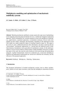
cracking of the weld in service. They will also validate the thermo-dynamic and kinetics calculations for postweld heat treatment. Macroscopic characterization of melt flow, heat transfer and hot cracking provides measured solidification conditions as inputs to microscopic models and validates the simulation results of the CFD model at macroscale. The parent material structure and properties (elastoplastic properties) characterization by experimentalists will be provided as input to related numerical models (e.g., life prediction model and thermomechanical simulation) as their inputs. RESULTS OF NUMERICAL MODELING AND EXPERIMENTAL CHARACTERIZATION Some representative results of this multiscale, multiphysics numerical modeling and experimental characterization work, which is currently in progress, are briefly introduced in this section. The details of respective numerical models and experimental techniques as well as their results will be published separately. MD Simulation Results In the MD simulation, in order to predict the interfacial energy and its anisotropy at the solid– liquid interface (as well as other parameters of interest), a layer of liquid phase was typically sandwiched by two layers of solid phase as shown in Fig. 2. A periodic boundary condition was applied and the whole system was equilibrated at the melting temperature. By analyzing the simulation results in the capillary fluctuation of the solid– liquid interface, the interfacial stiffness and, hence,
Fig. 2. Setup of the MD simulation domain (liquid atoms in blue and solid atoms in red)
102
Tong, Duggan, Liu, Xie, Dodge, Aucott, Dong, Davidchack, Dantzig, Barrera, Cocks, Kitaguchi, Lozano-Perez, Zhao, Richardson, Kidess, Kleijn, Wen, Barnett, and Browne
and interface free energy and its anisotropy, can be determined, providing input to the phase-field modeling. The major input expected by the MD modeling is the empirical interatomic potential, which is based on the embedded atom method as employed by this work. While the MD modeling is currently using the potential as obtained from the literature for now,14 the MintWeld ab initio modeling is formulating a better replacement for this potential.
5μm
8.20 μm
9.05 μm
Phase-Field Simulation Results Figure 3 displays the morphology of columnar dendrites growing in the weld pool of gas tungsten arc spot welding, predicted by the phase-field model15–17 at a time of 5 ms from the start of solidification. In this image, the values of the primary arming spacing are scaled by18 G 1/2V 1/4, where G is the thermal gradient and V is the solidification rate. It can be seen that the side branches of the dendrites are more easily formed at the top center of weld pool in comparison with those at the top edge. Although the solidification conditions that were used in the case study shown in Fig. 3 are obtained from literature,19 a coupled simulation using the front-tracking and CFD models has already finished a productive run and sent the predicted solidification conditions to the phase-field model. A case study of phase-field simulation will be run completely based on this solidification condition shortly. Coupling of Front Tracking Model with CFD Model
11.31 μm
Fig. 3. Morphology map predicted at different locations of the weld pool by phase-field modeling.
Using a case study of laser spot welding, the front-tracking model20,21 was fully coupled with a CFD model22 to predict the macroscopic evolution of temperature field and flow field as well as the mesoscopic evolution of dendritic structure (i.e., the envelops of dendrite tips). Figure 4a illustrates the temporal evolution of temperature field during the solidification stage of welding, which starts from the very moment that the laser power is turned off (at 5 s since the start of welding).
Fig. 4. Temporal evolution of (a) temperature field and (b) distribution of solid fraction during the cooling of weld, in which the pink curves highlight the position of solidification front.
Multiscale, Multiphysics Numerical Modeling of Fusion Welding with Experimental Characterization and Validation
(a)
103
(b)
Fusion boundary
Region B
Region A
8630
625
0.5 μm
5 μm
(c)
Fig. 5. (a) An SEM SE image using the in lens detector showing the cross-sectional TEM sample. (b) TEM dark-field image of region A with M23C6 (the white arrow). (c) A TEM bright-field image of the precipitate M7C3 carbides indicated with arrows in region B.
Figure 4b displays the temporal evolution of volume fraction of solid phase in the weld. It can be seen that, as the weld pool cools down, the solidification front migrates toward the center of weld pool, which is followed by the widening of the mushy zone and an increasing amount of completely solid phase. It has to be highlighted that, although the fronttracking model and CFD model are using different types of computational meshes and different numerical methods in their respective computation, they are directly linked closely together (at source code level) by full coupling based on data transfer in real-time computation. Numerical Modeling and Experimental Characterization of Cold Cracking Hydrogen is believed to have deleterious effects on the mechanical properties of welds and can lead to catastrophic failures in service. In particular, pipe lines in marine environments are significantly affected by the presence of hydrogen. TEM has been used to study the fusion zone microstructure of a dissimilar weld. A sample of
8630 steel with a 625 nickel alloy buttering layer was provided after a postweld heat treatment. Figure 5a shows the microstructure of the fusion zone. The fusion boundary is in the middle of the image as indicated by the dashed line. Two regions can be distinguished. The first is region A in the 8630 where a martensitic lath grain region was identified very close to the fusion boundary with a width of less than a few microns and Cr based M23C6 type carbides observed. The magnified TEM dark-field image is shown in Fig. 5b. The M23C6 type carbides are profuse, which can account for several percent in volume fraction at maximum in region A. The darker phases on the grain boundary (black arrows) in the equiaxed grain region in 8630 steel were identified as cementite. The second is region B, in the 625 alloy (right) side of the fusion boundary, previously called the ‘‘featureless zone’’; a fine distribution of high atomic number M7C3 carbides has recently been observed in this zone (Fig. 5c). A retrieved subsea specimen is presented in Fig. 6,23 which was sampled from a 8630-625
104
Tong, Duggan, Liu, Xie, Dodge, Aucott, Dong, Davidchack, Dantzig, Barrera, Cocks, Kitaguchi, Lozano-Perez, Zhao, Richardson, Kidess, Kleijn, Wen, Barnett, and Browne
Fig. 6. SEM backscatter image of cracks found in a retrieved subsea 8630-625 specimen.
welded joint that had been subsea for approximately 9 months. This joint was removed from a field in which failures were observed, but the sample itself was not thought to contain any macroscopic imperfections. Characterization by scanning electron microscope (SEM) revealed a number of cracks. This is an important observation as it demonstrates that interfacial cracks can develop subsurface and progressively, rather than in a single event. The loss of ductility and subsequent formation of these cracks can be attributed to hydrogen. By analyzing the fracture morphology and its relationship with the weld microstructure, as typically shown in Fig. 5, it believed that the presence of M7C3 carbides in region B provides a low-energy path for crack propagation. The experimental findings imply a hydrogen-induced decohesion mechanism along the M7C3-matrix interface succeeded by strain localization between the particles. Guided by the experimental observations, a numerical model for predicting hydrogen cracking was developed. The model is centered on a cohesive zone modeling (CZM) approach.24,25 The basic idea of CZM consists of modeling deformation and finally the decohesion of the material at a crack tip or at the interface between two dissimilar materials by a traction separation law (T–d). Cohesive elements can be imagined as interface elements with a thickness close to zero embedded in continuum elements. Fracture occurs at the interface between the cohesive zone and continuum elements. In this work, a cohesive element formulation is proposed in which the T–d law is a function of hydrogen content and the plastic deformation of the surrounding material. This model has been implemented as a user element in the commercial finite-element code ABAQUS. Figure 7a shows a unit cell of the case study, which contains a single M7C3 carbide particle. The particle is assumed to remain linear elastic with the surrounding matrix deforming. Cohesive zone elements are introduced at the interface between the matrix and carbide. Here, hydrogen is
Fig. 7. (a) Unit cell representing carbide–matrix system consisting of three regions: matrix, carbide, and carbide–matrix interface. (b) Evolution of plastic strain for increasing hydrogen content showing decohesion at the carbide/matrix interface leading to microcracks formation followed by localization of plastic flow acting as microcracks link up.
assumed to affect both the cohesive strength and the yield stress of the matrix. The hydrogen content was ramped up from zero to a maximum as the macroscopic nominal uniaxial strain is increased to 50%. Figure 7b shows the macroscopic stress–strain curve together with the distribution of microscopic effective plastic strain and the extent of the region around the particle, which has been found to decohere at three consecutive instants during the loading. The predicted failure surface is found to consist of planes of intense plastic deformation between dimples created due to decohesion around the particles, which is consistent with the morphology of failure surfaces generated as the result of crack growth through the featureless zone that was experimentally characterized in the MintWeld project. This numerical model can be embedded ahead of a crack tip and combined with models of hydrogen
Multiscale, Multiphysics Numerical Modeling of Fusion Welding with Experimental Characterization and Validation
105
Fig. 8. Optical image of ‘‘post-test’’ weld solidification.
diffusion and a macroscopic model of weld deformation in order to predict the detailed process of weld crack growth in service. Experimental Characterization of Hot Cracking and Melt Flow Hot cracking has been experimentally characterized based on in situ measurements of arc welding. During the welding process, associated parameters (e.g., temperature of parent metal and weld pool) were recorded, together with weld quality assessments of the test welds produced. Solidification cracks, as seen in Fig. 8, were witnessed in the post test specimens, allowing for detailed quantification, with fractography work ongoing. Emphasis was placed on the final stages of solidification at which solidification cracking can occur, and low-meltingpoint liquid films can be concentrated at grain boundaries. The experimental measurements benefit mesoscale and macroscale numerical modeling by providing macroscopic inputs of field variables. They are also validating the simulation results of microscopic models, referring to the morphology of solidification structure. High-speed camera and image analysis has been employed in order to visualize the flow field of melting in welding. Figure 9 shows a snapshot (optical image and flow field) of a case study of laser spot welding. As the surface tension gradient is negative, at this instance, the melt flows outward toward the ‘‘cold’’ edge of weld pool. The measured data of flow field is being used directly to validate the related simulation results of the MintWeld CFD model. DISCUSSION AND CONCLUSION In the MintWeld project, multiscale, multiphysics numerical modeling is being implemented in a novel and efficient way, in which the respective computational models are linked on neighboring spatial
Fig. 9. (a) Optical image of weld pool and (b) flow field of melt as analyzed by image analysis.
Fig. 10. An example of model linking on neighboring spatial scales.
scales. For example, as shown in Fig. 10, the phasefield model (on microscale) is only directly linked to the MD model (on atomic scale) and front-tracking model (on mesoscale). And the phase-field model, however, does not have any explicit data flow or
106
Tong, Duggan, Liu, Xie, Dodge, Aucott, Dong, Davidchack, Dantzig, Barrera, Cocks, Kitaguchi, Lozano-Perez, Zhao, Richardson, Kidess, Kleijn, Wen, Barnett, and Browne
data input/output with the ab initio model (on quantum scale). Utilizing this strategy of model linking, a multiscale problem is reduced to several individual two-scale problems. Because each numerical model interacts with their neighboring models (e.g., with their outputs as the inputs to the respective beneficiaries), the individual two-scale problems are not separated from each other but actually coupled. This model linking strategy results in significant convenience and efficiency of model development as well as numerical computations of the multiscale, multiphysics phenomena. Computational information will ultimately flow all the way through the length scales via percolation. In the experimental works of MintWeld, a variety of experimental techniques is employed in order to characterize the materials and the process of welding. The data from experimental measurements, as shown in Fig. 1, are actively contributing to the modeling work either as input parameters or via validation. Experimentalists and modelers are collaborating with a view to development of insights into the multiple physical phenomena across the length scales, which influence the success of fusion welding. ACKNOWLEDGEMENTS This research work is supported by the European Commission as part of the FP7 program, as the project, Modeling of Interface Evolution in Advanced Welding, Contract No. NMP3-SL-2009-229108. REFERENCES 1. Z. Jiao, C. Song, T. Lin, and P. He, Comput. Mater. Sci. 50, 3385 (2011). 2. J. Song and D.L. Srolovitz, J. Mech. Phys. Solids 57, 776 (2009). 3. X. Zhan, Y. Wei, and Z. Dong, J. Mater. Process. Technol. 208, 1 (2008).
4. W. Tan, N. Bailey, and Y. Shin, Comput. Mater. Sci. 50, 2573 (2011). 5. J. Zhou and H.L. Tsai, Int. J. Heat Mass Transf. 51, 4353 (2008). 6. G. Xu, J. Hub, and H.L. Tsai, Int. J. Heat Mass Transf. 52, 1709 (2009). 7. O. Grong, Metallurgical Modelling of Welding, 2nd rev. ed. (London, U.K.: Maney Publishing, 1997). 8. R.W. Hamilton, D. See, S. Butler, and P.D. Lee, Mater. Sci. Eng. A 343, 290 (2003). 9. P.D. Lee, A. Chirazi, R.C. Atwood, and W. Wang, Mater. Sci. Eng. A 365, 57 (2004). 10. J. Wang, M. Li, J. Allison, and P.D. Lee, J. Appl. Phys. 107, 061804 (2010). 11. M. Tong, J. Liu, Y. Xie, H.B. Dong, R.L. Davidchack, J. Dantzig, D. Ceresoli, N. Marzari, A. Cocks, C. Zhao, I. Richardson, A. Kidess, C. Kleijn, L. Hoglund, S.W. Wen, R. Barnett, and D.J. Browne, IOP Conf. Ser. Mater. Sci. Eng. 33, 012029 (2012). 12. S. McFadden and D.J. Browne, Appl. Math. Model. 33, 1397 (2009). 13. W.U. Mirihanage and D.J. Browne, Comput. Mater. Sci. 46, 777 (2009). 14. G.J. Ackland, M.I. Mendelev, D.J. Srolovitz, S. Han, and A.V. Barashev, J. Phys.: Condens. Matter 16, S2629 (2004). 15. B. Echebarria, R. Folch, A. Karma, and M. Plapp, Phys. Rev. E 70, 061604 (2004). 16. J.-H. Jeong, N. Goldenfeld, and J.A. Dantzig, Phys. Rev. E 64, 041602-1 (2001). 17. Y. Xie, H.B. Dong, and J.A. Dantzig (Paper presented at Solidification, EUROMAT 2011, Montpellier, 12–15 September 2011). 18. S.Z. Lu and J.D. Hunt, J. Cryst. Growth 123, 17 (1992). 19. W. Zhang, G.G. Roy, J.W. Elmer, and T. DebRoy, J. Appl. Phys. 93, 3022 (2003). 20. G. Duggan, W.U. Mirihanage, M. Tong, and D.J. Browne, IOP Conf. Ser. Mater. Sci. Eng. 33, 012026 (2012). 21. G. Duggan, M. Tong, and D.J. Browne, IOP Conf. Ser. Mater. Sci. Eng. 27, 012077 (2012). 22. Z. Saldi, A. Kidess, S. Kenjeres, C. Kleijn, C. Zhao, and I. Richardson (Paper presented at the 2nd European Conference on Microfluidics. Socie´te´ Hydrotechnique de France, SHF, December 2010). 23. M.F. Dodge, H.B. Dong, M. Milititsky, R.P. Barnett, V.F. Marques, and M.F. Gittos (Paper presented at OMAE201283402, Rio de Janeiro, 1–6 July 2012). 24. G.I. Barenblatt, Adv. Appl. Mech. 7, 55 (1962). 25. P. Sofronis, Y. Liang, and N. Aravas, Eur. J. Mech. A 20, 857 (2001).