The International Journal of Parallel, Emergent and Distributed Systems, Vol. 20, No. 1, March 2005, 69–84
Multi-shared-trees based multicast routing control protocol using anycast selection WEIJIA JIA†*, WANQING TU†, WEI ZHAO‡ and GAOCHAO XU§ †Department of Computer Engineering and Information Technology, City University of Hong Kong, SAR Hong Kong, China ‡Texas A&M University, College Station, TX, USA §Jilin University, China A novel internet multicast routing protocol is presented to possess efficiency and effectiveness for multicast packet routing with short delay, high throughput, resource utilization and scalability for a single multicast group g. The protocol has two features: (1) Multiple Shared-Trees (MST) are configured to provide efficient, dynamic and quality multicast routing; (2) Anycasting approach is applied by forming the tree roots into an anycast group so that the multicast packets can be anycast to the nearest node at one of the shared trees to achieve the best routing service for the packets. The performance of the MST protocol is analyzed through extensive simulations and compared with well-known source tree and shared-tree routing. Keywords: Anycast and multicast routing; Source tree; Shared-tree; Shortest path tree; Core-base tree; Scalability
1. Introduction Multicast routing has been regarded as a very important tool for many Internet applications such as video/audio conferencing, replicated database, information distribution, resource discovery, and replicated web publishing, etc. However, implementing an efficient multicast routing in the Internet is a challenging task and the following issues must be tackled: . Efficiency: Short end-to-end delay and high throughput should be achieved to meet the application requirements, particularly, that require quality of service. . Scalability: Multicast routing should be scaled to a large network without comprising the efficiency. . Resource utilization: The working load must be balanced and the network congestion must be avoided to enhance efficiency and scalability. Many well-known multicast routing protocols have been developed including Distance-vector multicast routing protocol (DVMRP) [16], Multicast extensions to open shortest-path first (MOSPF) [11], Protocol Independent Multicast (PIM) [5], and Core Based Tree (CBT) [1]. *Corresponding author. Email:
[email protected] The International Journal of Parallel, Emergent and Distributed Systems ISSN 1744-5760 print/ISSN 1744-5779 online q 2005 Taylor & Francis Ltd http://www.tandf.co.uk/journals DOI: 10.1080/17445760500033317
70
W. Jia et al.
There are two major approaches for the design of multicast routing: source-tree and sharedtree routings. Source-tree routing approach can be further divided into broadcast-and-prune (DVMRP and PIM Dense) versus those protocols that broadcast their group membership information (domain-wide reports of link state of MOSPF). The typical source-tree routing algorithm applies the shortest path tree (SPT) algorithm and separate multicast trees need to be computed, one for each sender. Routers implementing a link state algorithm periodically collect reachable information to their neighbors, and then flood this throughout the routing domain in so-called link state update packets. However, the flooding (broadcasting) of group membership information is the predominant overhead for the internetworking networks. The other limiting factor is the processing cost of Dijkstra calculation [3] to compute the shortestpath tree for each active source. Another problem associated with source-tree routing is that a router has to keep the pair information (source, group) and consequently may overwhelm the routers in a subnet or area. In reality the Internet is a complex, heterogeneous environment that potentially has to support many thousands of active groups, each of which may be sparsely distributed, and this technique clearly does not scale well. Because of its scalability and simplicity, CBT and PIM are two well-known shared tree multicast routing systems. PIM architecture also supports both shared and source-based distribution trees. When the members are sparsely distributed, PIM uses source-based tree for the routing multicast packets. When members are densely distributed, PIM adapts shared tree routing. An advantage of the shared-tree offers more favorable scaling characteristics than all other source-tree multicast algorithms [11,16]. The main drawback of using a shared-tree in a network is the “traffic concentration”: if every sender uses the same shared-tree, traffics may get congested along certain links of the shared-tree. Another drawback of the shared-tree is that the sender and receiver may not connect through the shortest path, hence, the end-to-end delay could be higher than the source tree routing counterpart. Anycast routing differs from unicast and multicast in which a message is either sent to one fixed destination or must be sent to every member in a group. Anycast service provides “a stateless best effort delivery of an anycast datagram to at least one host; and preferably only one host, which serves the anycast address” [12]. It was determined that the anycast addresses are allocated from the unicast address space with any of the defined unicast address format [4]. Several anycast routing techniques were provided in our previous papers [9,17]. To integrate both advantages of source-tree and shared-tree routing and overcome their shortcomings, this paper presents a novel multicast routing protocol by applying anycast routing and multiple shared-tree (MST) approaches. Therefore, the design of MST intends to enhance multicast efficiency, scalability, and reliability as comparable with the source and shared tree schemes. The rest of the paper is organized as follows. Section 2 discusses modeling and metrics of multicast routing algorithm. Section 3 presents the novel MST protocol. Section 4 demonstrates the performance of MST and Section 5 concludes the paper.
2. Notations, modeling and motivations 2.1 Notations . Network, router and delay: A network is modeled as a graph G ¼ ðV; EÞ where V is a finite set of vertices, representing the nodes (routers or switches) in the network
Multi-shared-trees based multicast routing
71
concerned. We use u, v, w to denote the nodes/routers and each router may have a number of interfaces. E is a finite set of edges. An edge (u, v) is the direct link between two nodes u and v. We use notation d(u,v) as the static delay function mapping from the edge (u,v) to some integer. The multicast destinations are these sites forming a group g and directly connected to the designated routers. . Path modeling: For routing a packet m, routers u and v may cooperatively decide a path P(u, v) from u to v. In general, a path P(v0, vn) is defined as the (non loop) route from v0 to vn through nodes v1, . . ., vn21. The shortest-path (SP) is applied from the perspective of unicast routing. There are several metrics for measuring the “shortest path”: hop counts or link static delay (i.e. the distance). For simplicity, we use terms “route” and “path” interchangeably. Path delay is defined as the sum of the delays of each edge in the path: dðv0 ; vn Þ ¼
n21 X
dðvk ; vkþ1 Þ
ð2:1Þ
k¼0
. Multicast delivery (distribution) tree T: is used to propagate IP multicast packets from some nodes in T to all leaves which are the packets’ destinations. Source tree may root at each source. A shared-tree Tu rooted at u is the shortest path tree from u to g and shared by all sources. Upstream and downstream represent the interfaces (entries) of a router/node u that are configured in the routing table of the tree. The direction known as “Upstream” is the direction from u toward the root of T. . Tree propagation delay: Typically, each packet must arrive on a router’s specific upstream interface and then be copied onto a (set of) downstream interfaces. For routers u and v on T, we use P(u, v, T) to denote the path from u to v along multicast tree T. According to equation (2.1), the static delay traversing along P(u, v, T) can be defined as d(u, v, T). Thus the overall tree propagation delay is calculated as Dðu; TÞ ¼ max{dðu; v; TÞ : ;v [ VðTÞ}
ð2:2Þ
. Multicast routing performance metrics: Three quantities are particularly interested in characterizing the performance of multicast routing algorithms [2]: 1.
Multicast Transmission Delay (TD) is measured as the maximum time traversed by a packet from a source to all destinations. It is the upper bound of the delay a multicast packet experienced in network G (without considering any queuing delay). The maximum transmission delay is considered through a source-receiver path, as opposed to average source-receiver delay. Under such assumption, the (minimum) delay from an off-tree node u to all the members of group g along tree T is denoted as TDs and TDðu; g; TÞ ¼ dðu; vÞ þ Dðv; TÞ
2. 3.
ð2:3Þ
where v is a first on-tree router in the path P(u, r) and r is the core (root) of tree T. Parameter g is omitted if context is clear. Bandwidth-Consumption (BC) is measured as the total number of links used to deliver a packet from a source node to all receiver nodes. Traffic-Concentration (TC) is measured as the number of packets transmitted across each link per unit time.
72
W. Jia et al.
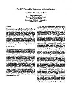
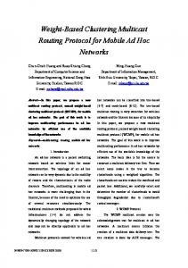
2.2 Problems with single shared tree multicast A Single Shared Tree (SST) may be shared by all of the group’s sources and receivers. The establishment of SST can be briefly described in the following three steps: Step 1. Selecting a root (core) node for a given multicast group g; Step 2. For each member in the multicast group, locating the shortest path from the member to the root; Step 3. Merging the shortest paths identified in Step 2. Dijkstra algorithm [3] is used to identify the shortest path. As a result, the tree is formed and called a core-based multicast tree (CBT) [1]. With the CBT approach, a multicast packet m is first transmitted from its source towards the root and then is dispatched (propagated) to all the branches of the tree for the delivery to all receivers eventually. SST routing algorithm relies on the core or a rendezvous point (PIM term), which could be a single-point (bottleneck) or congestion point. When traffic load is higher and many packets traverse the same set of links to the core, the core could become the bottleneck. The traffic may cause the longer delay for the multicast packets. We use figure 1 to illustrate the problems of SST (CBT). Let g ¼ {R1 ; R3 ; R6 } and the shared tree T with VðTÞ ¼ {R1 ; R3 ; R6 ; R4 }; EðTÞ ¼ {ðR1 ; R4 Þ; ðR3 ; R4 Þ; ðR6 ; R4 Þ}: R4 is the core and a set of sources s ¼ {R5 ; R7 ; R8 ; R10 }: The labels denote the delay on each link. With SST approach, TDðR5 ; TÞ ¼ dðR5 ; R6 Þ þ DðR6 ; TÞ ¼ 4 þ 7 ¼ 11; TDðR7 ; TÞ ¼ dðR7 ; R6 Þ þ DðR6 ; TÞ ¼ 4 þ 7 ¼ 11; TDðR8 ; TÞ ¼ dðR8 ; R6 Þ þ DðR6 ; TÞ ¼ 4 þ 7 ¼ 11 and TDðR10 ; TÞ ¼ dðR10 ; R6 Þ þ DðR6 ; TÞ ¼ 4 þ 7 ¼ 11: Similar to figure 1, figure 2 shows two shared-trees T1 and T2 where VðT 1 Þ ¼ {R1 ; R3 ; R6 ; R4 }; EðT 1 Þ ¼ {ðR1 ; R4 Þ; ðR3 ; R4 Þ; ðR6 ; R4 Þ} rooted at R4 ; and VðT 2 Þ ¼ {R1 ; R2 ; R3 ; R6 }; EðT 2 Þ ¼ {ðR1 ; R2 Þ; ðR2 ; R3 Þ; ðR1 ; R6 Þ} rooted at R1. The corresponding delay for TDðR5 ; T 2 Þ ¼ dðR5 ; R1 Þ þDðR1 ; T 2 Þ ¼ 2 þ 6 ¼ 8; TDðR7 ; T 1 Þ ¼ dðR7 ; R6 Þ þ DðR6 ; T 1 Þ ¼ 4 þ 7 ¼ 11; TDðR8 ; T 2 Þ ¼ dðR8 ; R1 Þ þ DðR1 ; T 2 Þ ¼ 2 þ 6 ¼ 8 and TDðR10 ; T 1 Þ¼dðR10 ; R6 Þ þ DðR6 ; T 1 Þ ¼ 4 þ 7 ¼ 11:
Figure 1. SST approach.
Multi-shared-trees based multicast routing
73
Figure 2. Multiple shared trees.
By SST approach, the average transmission delay is 11, but with the multiple-tree approach, the average transmission delay is 9.5. Now consider the problem of traffic concentration. The approach of multiple shared trees may alleviate the potential problem of traffic congestion. If SST approach is used, node R9 could be easily congested as the sources may transmit their traffics through R9 to the core. Clearly in MST approach, the multicast traffic can be split on the trees T1 and T2. 3. The protocol As discussed in the previous subsections, we have observed that a single shared tree may result in traffic concentration and longer delay. To cope with the problems, a novel multiple shared multicast tree (MST) protocol is designed to attain efficiency, scalability, reliability and compatibility. More specifically, MST is presented in this section intending to achieve better performance in terms of TD, BC and TC. To realize MST, two sub-protocols must be designed: (1) Multiple tree configuration sub-protocol (MTC-protocol) copes with multiple tree configurations by minimizing the cost of establishment of the routing tables. (2) Dynamic packet forwarding sub-protocol (DPF-protocol) takes the dynamic network traffic into consideration by selecting a multicast routing tree for a better routing performance. 3.1 Multiple tree configurations protocol (MTC) The purpose of MTC is to establish the multiple shared trees for the provision of best possible multicast routing efficiency and scalability while keeping the lower configuration cost. To build-up the trees, two essential issues are identified: (1) The metrics (i.e. the benefits) for the designs of multiple trees and (2) multiple shared tree configurations. Clearly multicast routing efficiency and scalability cannot be achieved at the same time and there is a trade-off between the two parameters. It is known that the source-tree and single shared tree may not be scaleable or effective. Targeting at these issues, MTC is designed in two executing stages:
74
W. Jia et al.
(1) Configuration of a primary shared tree and (2) Decision made for the benefits of secondary trees specification and configuration in terms of the primary tree. 3.1.1 Configuration of primary tree TP. Core selection: setting-up a minimum Steiner tree is the common practice for the design of the shared tree for minimizing the cost of network resources. Finding a minimum Steiner tree is a NP-complete problem and an algorithm that builds a tree for multicast whose cost is less than twice the minimum cost was presented in [10,15]. Some researchers study how to improve the shared-tree multicast performance by selecting a satisfied core. As indicated in [2], the choice of the core will influence the shape of the multicast routing tree and affect the performance of the routing schemes. The core can be selected in terms of group center or network center. But to calculate the center position may require considerable computation cost, and also the parameters must be known before. Various heuristics for the core selections were investigated in [14]. To alleviate the set-up cost, we will use the random generation approach for the selection of the primary core. This approach has been investigated in [2] as the randomized generation only requires the information for the network G. Members join TP. A host wanting to join a multicast group issues an IGMP Host Membership Report [6]. This message informs its local SST-aware router(s) that the host wishes to receive the multicast packets addressed to group g. Upon receipt of IGMP host membership report for a new group, the local router issues a join request (like CBT approach) hop by hop toward the group’s core r. If the join request encounters a router, which is already on the group’s shared tree before it reaches r, that router issues a join-ack hop by hop back toward the sending router. The core router r is ultimately responsible for responding with a join-ack if the join request does not encounter an on-tree router along its path toward r. 3.1.2 Secondary multiple shared-tree configurations. The motivation of establishment of multiple shared trees is to enable the routers to dynamically switch between the different routing paths (trees). The motivation of switching between the trees may distribute the multicast traffics over the trees and avoid possible congestion, eventually providing the short end-to-end multicast delay. But establishment of the trees requires considerable effort and may bring substantial overhead over the network. Therefore, we intend to configure the minimum number of the shared trees while maintaining multicast routing quality. The establishment of shared trees must consider the trade-off of the configuration cost and the efficiency of multicast routing. Metric for selecting the multiple tree roots: multicast propagation delay is taken as the criteria for building-up the secondary tree. Given the primary shared tree T with root r, in lines of equation (2.2), to build another tree Tu rooted at u, the routing delay for T and Tu must be derived and denoted as D(u, T) and D(u, Tu), respectively. Since Tu is the shortest tree rooted at u, there exists Dðu; TÞ .$ Dðu; T u Þ: Define Bf(u, Tu, T) as the routing benefit factor for multicast routing on tree Tu over the tree T, then Bf ðu; T u ; TÞ ¼ Dðu; TÞ 2 Dðu; T u Þ
ð3:1Þ
It can be seen that the set up of the secondary shared tree Tu is meaningful only when Bf ð·Þ . 0: Of course we wish to maximize Bf(·) when tree Tu is chosen for the distribution of multicast packets. Of course, the threshold D may be defined as any non-negative value such
Multi-shared-trees based multicast routing
75
Figure 3. (a) The topology of multiple shared trees. Multiple tree routing table for: (b) Router R5, (c) Router R6, (d) Router R7, (e) Router R8 and (f) Router R10.
76
W. Jia et al.
that as long as Bf ðu; T i ; T p Þ . D; the secondary tree Ti is configured and the corresponding routing table can be set up. We have the following secondary tree set-up algorithm: Algorithm establishment secondary_tree Input: Multicast group G ¼ {m1 ; . . .; mn } and the primary tree T p ¼ {v1 ; v2 ; . . .; vk } and finite set {Dðvi ; T p Þji ¼ 1; . . .; k}; Output: the secondary hierarchical trees, T j1 ; . . .; T jl where vji [ {v1 ; v2 ; . . .; vk } 2 {core} and l , k. Begin 1. for i ¼ 1 to k do 2. begin 3. Calculate the max distance from vi to the group members by 4. Dðvi ; GÞ ¼ max{dðvi ; mj Þji ¼ 1; . . .; k & j ¼ 1; . . .; n}; 5. if Dðvi ; GÞ , Dðvi ; T p Þ then 6. Initiate the configuration for the related nodes to set up tree Ti rooted at vi; 7. end; end. The cost of setting up the secondary can be dynamically adjusted in accordance with the availability of a router’s ability (memory or other cost, etc.). Let T P ¼ T 1 be the primary shared tree and T2, . . ., and Tk be the secondary shared-trees. A router u is known as the ontree router if u is on at least one of the trees at Ti where i ¼ {1; . . .; k}: An on-tree router may configure several shared-trees. When a packet reaches an on-tree router, the router must decide to which shared tree to propagate the packet. The structure of multicast routing table is similar to forwarding information base (FIB) [1]. Routing table configurations: the configuration of the multiple routing tables is similar to approach of normal multicast configuration. We agree that the configurations may require the cost higher than a single shared tree configuration, but the configurations only cost the protocol set-up time, not the running time. We use the topology shown in figure 3 as an example. Let the multicast destination group g ¼ {R5 ; R7 ; R10 }: R6 is selected as the center of the group g which is used as the root for creating the primary shared-tree T1 and VðT 1 Þ ¼ {R5 ; R6 ; R7 ; R8 ; R10 } are nodes of T1. The next step is to select some routers in V(T1) as the roots of the secondary shared-trees. Defined threshold D ¼ 0: For each router in V(T1), it can be seen that Bf ðR5 ; T R5 ; T p Þ ¼ DðR5 ; T 1 Þ 2 DðR5 ; T R Þ ¼ 6 2 6 ¼ 0; Bf ðR6 ; T R6 ; T 1 Þ ¼ 3 2 3 ¼ 0; Bf ðR7 ; T R7 ; T 1 Þ ¼ 6 2 6 ¼ 0; Bf ðR8 ; T R8 ; T 1 Þ ¼ 4 2 4 ¼ 0 and Bf ðR10 ; T R10 ; T 1 Þ ¼ 6 2 4 ¼ 2 . 0: Thus R10 is the only router selected for configuring the secondary shred-tree. 3.1.3 Off-tree router anycast configuration. With the multiple shared trees T1,T2,. . ., Tk in network G, routers can be categorized as on-tree and off-tree routers. An anycast address A can be accommodated to configure to all on-tree routers. Therefore, an off-tree router is able to forward a multicast packet to the “nearest” router with address A by point-to-point transmission, which does not have a single point problem as associated with the single tree approach [9].
Multi-shared-trees based multicast routing
77
In MST, the number of the on-tree routers, in general, is more than that on a single shared tree T1. If all of them are configured with anycast address, the configuration cost would be much higher. To reduce the cost of configuration of the anycast group, only the roots of the trees are configured to accommodate the anycast address. Therefore, it can be seen that the number of the routers configured to the anycast address is much less than that of on-tree nodes in Tp. The routing table consists of the fields of [Anycast address & Dest, next hop, Delay ]. Figure 4 shows anycast routing tables corresponding to the topology in figure 3(a). 3.2 Dynamic packet routing sub-protocol (DPR) In the shared tree routing such as CBT, the source outside the tree will use point-to-point routing for forwarding a multicast packet to one of the on-tree nodes in respect of multicast tree selection. DPR is designed to accommodate the dynamic traffic and efficient routing of multicast requests. To route a multicast packet for a SST, two distinct steps will be taken: (1) the multicast packet is unicast to the core of the shared tree T1; (2) Along the tree, the multicast packets are dispatched to all the branches of the tree and eventually delivered to all members in the recipient group g. This sub-protocol intends to transmit the packets through dynamic routing paths to achieve a short end-to-end delay and attain the efficient utilization of network resources. We thus differentiate the multicast packets as off-tree and on-tree packets and they are dealt with respects of: 1. Off-tree Packet Routing Strategy: The off-tree routers must decide how to transmit the packet to the shared trees. 2. On-tree Packet Forwarding Strategy: Once the packets are on one of the trees, the packets must be forwarded to the final destinations (receivers) in the efficient way. 3.2.1 Off-tree router routing algorithm. As we mentioned that SST may cause the traffic concentration on certain links, in particular, the links near the core. Therefore, we propose to apply anycast routing for the multicast packets that reaches one of the off-tree routers. An off-tree router, upon reception a multicast packet m destined at group g, will
Figure 4. Anycast Routing tables R1, R2 and R9. The shortest delay for a packet to reach: (a) R6 from R1 is 2 and 6 the shortest delay to R10 is 5, (b) R6 is 1 (direct connect) and (c) R10 from R9 via R13 is 3.
78
W. Jia et al.
tag (or add) anycast address A to the packet and make it an anycast packet m(A). Then anycast routing protocols can be applied as indicated in [9,17]. Denote the anycast group address A and all the roots (routers) of the shared trees are assigned the address A and the packet m(A) is forwarded to any router with address A as the destination. In the following subsections, we discuss the destination selection algorithm. 3.2.1.1 Destination selection Destination selection is a critical problem for the efficiency of the off-tree packet routing. The uniqueness of destination(s) in unicast eliminates this problem in the selection process. Here we first adapt randomized approach for destination selection. Specifically, for an anycast group each off-tree router keeps the list of weights, each corresponds to the interfaces (see figure 4). Their weights are denoted as W1, W2, . . ., WL, respectively. The weight of a destination represents the probability that the destination is to be selected. Thus, a member with higher weight value will have higher probability to be selected than those with lower weight values. The assignment of weights is subject to the following constraint L X
W i ¼ 1:
ð3:5Þ
i¼1
. Basic Weight Assignment Algorithm. The basic idea of this algorithm is that all members in g(A) will have equal probabilities to be selected as the destination of the multicast packets. To force such an even distribution, the weights associated to individual members must be the same, that is, for i ¼ 1; 2; . . .; L and W i ¼ 1=L: The weights enable the multicast traffic to be evenly distributed over the network towards the routers on the shared trees. This algorithm uses no system status; particular the delay or traffic information is not used except the number of routers that are assigned with address A. Since the algorithm treats all the routers evenly, therefore, the algorithm is called “unbiased” algorithm. . Weight Assignment based on Route Distance. The packets with short delay will consume less resources. Hence, a smart decision selection algorithm should prefer destinations with short route delay (distance). Based on the above consideration, a rule of thumb is that weight associated with a destination should be inversely proportional to the delay of the route. That is, for i ¼ 1; 2; . . .; L; W i ¼ 1=Di
ð3:6Þ
where Di is the value of the route (static) delay leading to destination i. To satisfy equation (3.5), the weights should be properly normalized, i.e. for i ¼ 1; 2; . . .; L; 1=Di wi ¼ PL j¼1 1=Dj
ð3:7Þ
Once the tree is decided, the routing can be done as the single shared tree approach. In the MST multicast routing, the anycast routing technique is used to select a suitable tree from these multiple shared-trees (see next section). . Weight Assignment based on Route Distance and Queuing Length. The dynamic routing will take the traffic into consideration and the real-time traffic can be reflected in the weight.
Multi-shared-trees based multicast routing
79
Note that anycast routing based on weight selection may have the problem of looping. Thus an additional mechanism should be enforced to avoid possible loop. The approaches considered may be the configuration of an anycast tree or include time to live (TTL) in the packet field. The details of anycast routing algorithms were discussed in [17].
3.2.2 On-tree router multicast quality routing algorithms. IPv4 (TCP) packet header has incorporated the field Type of service (TOS) for indicating the different types of messages. The header information is assumed to be accessible by the Internet routing protocol. To simplify the discussion, we only differentiate the packets that request minimum delay (denoted as min-d) from the rest service (i.e. the best-effort) service. The TOS header information is denoted as m.TOS in the following discussions. Once the packet m reaches any of the router u on a tree T, u may strip the anycast address from the packet and decide the routing strategy for m. If u has the on-tree router for several such trees a routing strategy is required to select a suitable tree T, which is called the destination tree. To enable an on-tree router to select the appropriate tree for multicasting the packet, the following tree routing polices are applied in the MST protocol. (1) For the min_d multicast packets, the packets are transmitted along the shortest path tree; (2) For the normal packets, the multicast can be forwarded to the primary (shared) tree. By this token, the MST routing algorithm is depicted below (figure 5). We use figure 4 again as an example to illustrate the MST protocol (figure 5). Assume multicast group g ¼ {R5 ; R7 ; R10 }: Two shared-trees T1 and T2 are configured and T1 is the primary tree rooted at R6 and R10 is the root of secondary tree T2. Anycast address A is assigned to the routers in {R6, R10}. Consider a multicast packet m initiated from R9 (or the host attached to R9), R9 tags m as m(g, A) and uses anycasting to transmit m to the nearest router with anycast address R10 via next hop R13. Router R10, upon reception of the packet, then decide the destination tree is T2, it restores m(g, A) as m(g, T2) and propagates m to R5 and R7, respectively. This routing incurs the total delay of 7. If the only shared tree T1 is applied, m has to be sent to R6 via R5 and then R6 eventually propagates to R7 and R10, respectively. The total delay is 9.
4. Performance evaluation This section reports performance observations and evaluations from MST protocol. To obtain the performance data, we use a discrete event simulation model to simulate data communication networks. The simulation program is written in C and runs in a SUN SPARC workstation 20. The network simulated is the ARPANET published in June 1975 (as shown in figure 6). Suppose the bandwidth of each link is 10 Mbps, the delay of each link is one value randomly selected from the set of (1,2,3,4,5) (milliseconds). During the simulation, 20,000 multicast packets are randomly generated as a Poisson process. The average size of the packets is 1200 B such that 1000 packets can be transmitted along each link per second. Simulation starts when the first multicast packet generates and ends when all the packets reach their destinations.
80
W. Jia et al.
Figure 5. Algorithm MST_Routing.
4.1 Simulation model The following performance metrics are taken into consideration for the performance evaluations: (1) Average transmission delay: It is measured as the maximum time traversed by a packet from a source to all destinations. In a simulation session, the average transmission delay is computed through dividing the sum of all packets’ transmission delay by the number of packets all sources sent. (2) Average Bandwidth Consumption: It is defined as the total number of hops that a multicast packet travels in order to reach all the members in the multicast group. The average bandwidth consumption is computed by dividing the total number of hops measured in a simulation session by the number of packets received. (3) Throughput: The throughput is defined as the maximum number of packets transmitted per time unit.
Multi-shared-trees based multicast routing
81
Figure 6. ARPANET in June 1975.
(4) Mean standard deviation of link utilization: In the simulation, suppose the total simulation time is T, and the busy time of link Li is ti in the period of T, then the utilization of Li is defined as ›i ¼ ti =T: q For links L1,L2,. . .,Lk,ffi let their utilization be ›1, ffiffiffiffiffiffiffiffiffiffiffiffiffiffiffiffiffiffiffiffiffiffiffiffiffiffiffiffiffiffiffiffiffiffiffiffiffiffi Pk Pk ›2,. . .,›k and F ¼ ð i¼l ›i Þ=K: Thus ð i¼1 ð›i 2 FÞ2 Þ=K should be the standard deviation of link utilization. The lower the standard deviation is, the more balanced the loads of links are and the better capability to prevent the congestion that the system has. Because all links on tree have the same multicast loads and all multicast packets must pass all links on tree, so we only consider off-tree links. 4.2 Systems simulated Three types of multicast routing approaches are used for the comparison: The shortest path tree (SPT), core based tree (CBT) and our multiple shared tree (MST). The goal in the shortest path tree algorithms is to compute a tree rooted at the sender and spanning all the receivers such that the distance between the sender and each receiver along the tree is the minimal. SPT is the typical method of source based tree algorithms and CBT is a single shared tree algorithm. The core is selected from the center of the multicast group.
4.3 Performance observation The simulation results of the average delay metric are shown in figure 7. The results of the network resource usage metric are shown in figure 8, the results of the average delay increasing as the network load are shown in figure 9, and the maximum system throughput
82
W. Jia et al.
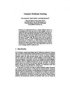
Figure 7. The delay under the different number of group members (lower load).
are given in the figure 9; the results of the standard deviation of links’ utilization are given in figure 10. From these simulation results, we have the following observations: 1. Under the lower load circumstance, the delay is mainly related to the distance from the source to the group members. Because the SPT approach always transmits the multicast packets to group members along the shortest paths from the source to the group members, so it can achieve the best delay performance among these simulated systems when the network is lightly loaded. Among the three approaches simulated, SPT achieves the best delay performance and CBT the worst. MST can significantly improve the delay performance comparing with CBT, its delay performance is near to SPT. 2. Figure 8 shows the average number of links used by these routing approaches. In general the number of links used will be increased with the number of the group members. Figure 9
Figure 8. Links under the different number of group members.
Multi-shared-trees based multicast routing
83
Figure 9. Delay under different arrival rate.
shows that with the same number of group members, MST makes use of the minimum number of links for transmitting a multicast packet whereas SPT uses the maximum links. Comparing with CBT and SPT, MST can use less resources to transfer a multicast packet to all multicast members than SPT and CBT. 3. Figure 9 shows that the delay increases as the packet arrival-rate increases. The system saturate points for SPT, CBT and MST are 3.5, 4.6 and 5.4 packets/ms, respectively. In another word, MST achieves the maximum throughput. It revels that under the same conditions, the less resources a system consumes, the higher throughput can be achieved. 4. In figure 10, the standard deviation of links utilization is lower when MST is compared with CBT. It shows that MST has the higher capability of preventing the congestion and of balancing the traffic loads than CBT, particularly in the heavy traffic situation. The capacity of MST to balance the traffic loads is near to that of SPT.
Figure 10. The standard deviation of link utilization under different arrival.
84
W. Jia et al.
5. Conclusions Poor scaling properties are inherited in multicast routing algorithms that build source-based trees. If S is the number of active sources per multicast group, and N is the number of multicast groups, the source-based multicast algorithm results in a scaling factor of S £ N. Shared-tree approaches significantly improve the overall scaling factor of S £ N in the source-based tree to just N. The scaling factor of MST for an off-tree router is also close to k £ N, where k is the number of the shared trees per group. Generally speaking, k is much smaller than S and it is a constant, so the scalability is comparable to the shared-tree. MST has achieved a good performance test through wide experiment such as the short transmission delay and the high capacity to balance the traffic load over SST and CBT. MST has high capacity to balance the traffic load and balanced resource utilization while attains the higher system throughput.
Acknowledgements The work is partially supported by Research grant council (RGC) Hong Kong, SAR China under grant nos. CityU 1055/00E (9040687) and CityU 1039/02E (9040596) and CityU Strategic grant no. 7001587 and 7001709.
References [1] Ballardie, A.J., Francis, P.F. and Crowcroft, J., 1993, Core based trees. Proceedings of ACM SIGCOM, San Francisco, pp. 85–95. [2] Calvert, K.L., Zegura, E.W. and Donahoo, M.J., 1995, Core selection methods for multicast routing. Proceedings of ICCCN’ 95, pp. 638 –642. [3] Dijkstra, E.W., 1959, A note on two problems in connection with graphs, Numerische Mathematik, 1. [4] Deering, S. and Hinden, R., 1998, Internet Protocol version 6 (IPv6) specification, RFC 2460. [5] Deering, S., Estrin, D.L., Farinacci, D., Van Jacobson, Liu, C. and Wei, L., 1996, The PIM architecture for wide-area multicast routing, IEEE/ACM Transactions on Networking, 4(2), 153 –162. [6] Hedricks, C.L., 1991, An Introduction to IGRP (Center for Computer and Information Services, Laboratory for Computer Science Research, Rutgers University). [7] Halabi, B., 1997, Internet Routing Architecture (Cisco Press). [8] Jia, W., Zhao, W., Xuan, D. and Xu, G., 1999, An efficient fault-tolerant multicast routing protocol with corebased tree techniques, IEEE Transactions on Parallel and Distributed Systems, 10(10), 984–999. [9] Jia, W., Xuan, D. and Zhao, W., 2000, Integrated routing algorithms for anycast messages, IEEE Communications Magazine, 38(1), 2–12. [10] Kou, L., Markowsky, G. and Berman, L., 1981, A fast algorithm for steiner trees, Acta Informatica, 15, 141–145. [11] Moy, J., 1998, OSPF: Anatomy of an Internet Routing Protocol (Reading, MA: Addison-Wesley). [12] Partridge, C., Mendez, T. and Milliken, W., 1993, Host anycasting service, RFC 1546. [13] Shields, C. and Garcia-Luna-Aceves, J.J., 1997, The ordered core based tree protocol, Proceedings of IEEE Infocom’97 (Japan: Kobe). [14] Thaler, D.G. and Ravishankar, C.V., April 1997, Distributed center-location algorithms, IEEE Journal on Selected Areas in Communications, 15(15), 291–303. [15] Wall, D.W., February 1982, Selective broadcast in packet-switched networks. Proceedings of the Six Berkely Workshop on Distributed Data Management and Computer Networks, pp. 158–239. [16] Waitzman, D., Partridge, C. and Deering, S., 1988, Distance vector multicast routing protocol, RFC 1075. [17] Xuan, D., Jia, W. and Zhao, W., June 2000, Routing algorithms for anycast messages, IEEE Transactions on Parallel and Distributed Systems, 11(6), 571 –588.