Split decoding [13]. The paper is organized as follows: Section II reviews the Split-Row and Split-Row Threshold decoding algorithms. Multi-Split-Row Threshold ...
Multi-Split-Row Threshold Decoding Implementations for LDPC Codes Tinoosh Mohsenin, Dean Truong and Bevan Baas ECE Department, University of California, Davis Abstract— The recently introduced Split-Row Threshold algorithm significantly improves the error performance when compared to the nonthreshold Split-Row algorithm while requiring a very small increase in hardware complexity. The Multi-Split-Row Threshold decoding algorithm presented in this paper enables further reductions in routing complexity for greater throughput and smaller circuit area implementations. Several Multi-Split-Row Threshold decoder designs have been implemented in 65 nm CMOS and the impact of the different levels of partitioning on error performance, wire interconnect complexity, decoder area, and speed are investigated. The Split-Row-16 Threshold decoder occupies 3.8 mm , runs at 100 MHz, delivers a throughput of 13.8 Gbps at 15 iterations and is only 0.28 dB and 0.22 dB away from SPA and MinSum Normalized.
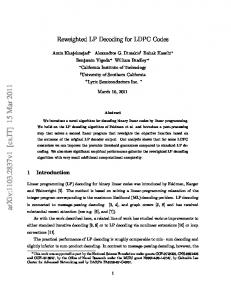
I. I NTRODUCTION Low density parity check codes were first introduced by Gallager [1] in 1962. Due to their excellent error performance, LDPC codes have recently received significant attention and have been adopted by many recent communication standards such as 10 Gigabit Ethernet (10GBASE-T) [2], digital video broadcasting (DVB-S2) [3] and WiMAX(802.16e) [4]. However, due to the high interconnect complexity and high memory bandwidth requirements of existing decoding algorithms, implementing high throughput and energy efficient LDPC decoders remains a challenge. regular LDPC code is a block code defined by A a binary parity check matrix with code length , information length , column weight which is the number of ones per column, and row weight which is the number of ones per row. LDPC codes are commonly decoded by an iterative message passing algorithm consisting of two sequential operations (or twophases): check node update (row processing) and variable node update (column processing). A simple illustration of this algorithm is shown in Fig. 1 (a). The parity check matrix defines the assignment (i.e. dependency) between which check nodes to which variable nodes, and vice versa. In row processing, check nodes receive messages ( ) from their assigned variable nodes, perform parity check operations and send their results ( ) back to the variable nodes. For column processing, the variable nodes update their estimates of the decoded bits using the messages ( ) from their assigned check nodes and the channel data ( ) and send their results ( ) back to the check nodes. This process continues iteratively until all errors are corrected or the number of iterations reaches a user defined maximum. Sum-Product (SPA) [5], MinSum (MS) [6] and MinSum Normalized [7] are near-optimum decoding algorithms which are widely used in LDPC decoders and are considered as standard decoders. These algorithms propose different check node processing methods but use the same variable node update. The major drawback of standard decoding algorithms is that they require variable nodes to send their messages to all their assigned check node for a single check node update. This communication leads to greater global interconnect complexity for large row weight ) and for large parity check matrices. Considering codes ( the fact that even if a decoding message is represented by a few
bits (e.g. ), the interconnect complexity will sharply increase with every increment in row weight resulting in larger and slower circuits [8], [9]. Previous studies for reducing wire interconnect complexity are based on reformulating the message passing algorithm [10], [11], [12]. This paper introduces Multi-Split-Row Threshold decoding which significantly reduces wire interconnect complexity and considerably improves the error performance compared to non-threshold MultiSplit decoding [13]. The paper is organized as follows: Section II reviews the Split-Row and Split-Row Threshold decoding algorithms. Multi-Split-Row Threshold and its error performance results are presented in Section III. In Section IV, the results of several Multi-SplitRow Threshold decoder designs have been implemented highlighting the impact of the different levels of partitioning on wire interconnect complexity, decoder area, and decoder speed. II. S PLIT-ROW AND S PLIT-ROW T HRESHOLD D ECODING A LGORITHMS Recall that a standard message passing two-phase algorithm consists of a check node update followed by a variable node update as shown in Fig. 1 (a). For Split-Row [14], [13] and Split-Row Threshold [15], [16], their decoders partition the check node processing into two or multiple nearly-independent partitions, where each check node processor simultaneously computes a new message while only using minimal information from its adjacent partitions. Split-Row is illustrated in Fig. 1 (b) showing how the check node processing is ) for partitioned into two blocks. A single bit of information ( each check node processor must be sent between partitions to improve error performance. The major drawback of Split-Row is that it suffers from a 0.5– 0.7 dB error performance loss, when compared to MinSum Normalized and SPA decoders. This degradation in performance is dependent on the number of check node partitions, and is the key obstacle in practical Multi-Split implementations. For MinSum Split-Row each partition has no information of the minimum value of the other signal is sent to minimize the error due to partition, and a incorrect sign information of the true check node output . The Split-Row Threshold algorithm mitigates the error caused by incorrect magnitude by providing a signal, , which indicates whether a partition has a minimum less than a given threshold ( ). This causes all check nodes to take the min of their own local minimum or . Thus, any large deviations from the true minimum because of the partitioning is reduced, which then makes Multi-Split implementations feasible. ) Figure 1 (c) shows the additional single bit signal ( added to the original Split-Row architecture by the Split-Row Threshold algorithm. This signal allows the Split-Row to remain essentially unchanged while adding some extra logic and minimal wiring to improve error significantly [15]. Therefore, the Split-Row architectures reduce the communication between check node and variable node processors, which is the
Ȝ
!'
'(
Initialization !#
'( Check proc
ȕ
!!
'( 134.56676.8679:93;34
+.+B;34!-7C!#.G63H3I:;
!%
'(
!)
'(
!&
Variable proc sp0
Variable proc sp0 Syndrome check
(b)
'(
Variable proc sp0
Variable proc sp0 Syndrome check
(c)
Fig. 1. Block diagram of (a) standard two-phase decoding (b) Split-Row (c) Split-Row Threshold block diagram
!
!"#
!"$
!"%
!"& $ +,-./012
01(.*123-4.#*+7
$"%
01(.*123-4.#*+$4256%
01(.*123-4.#*+$42567
!$
!"!$ !
!%
!"!% !
#$%&
!(&8 $
!"!(&8 $ !
!(
!"!( !
,#-./!"#$ #$%&
!"#$ #$%& #$%&
03)345 '$*64
!""$ !
#$%& !"#% #$%& !""'()*+# !
&!'()*+#&8 $ 9&!'()*+#&: $&! &!'()*+#
!"!'()*+# !
#$%&
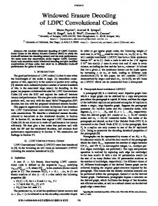
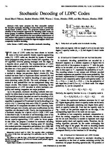
III. M ULTI -S PLIT-ROW T HRESHOLD Multi-Split-Row Threshold is similar to Multi-Split-Row [13] where partitions and each one the parity check matrix is divided into is processed simultaneously. However, unlike Multi-Split-Row, each partition of Multi-Split-Row Threshold sends the status of its local to the next partition with a single minimum against a threshold . wire, called The block diagram of Multi-Split-Row Threshold decoding with Spn partitions, highlighting the and passing signals, is shown in Fig. 2. These are the only wires passing between the partitions. In each partition, local minimums are generated and compared with a threshold simultaneously. If the local minimum is smaller than then the signal is asserted high. The magnitude of the check node outputs are finally computed using local signal from neighboring partitions. minimums and the If a local partition’s minimums are larger than , and at least one of the signals is high, then is used to update its check node outputs. Otherwise, local minimums are used to update check node outputs. The check node outputs are normalized with a correction factor which is in the range of 0.4-0.2 (depending on the level of split) before being sent to the variable nodes. The optimal values of are found empirically through correction factor and threshold simulation [16]. Unlike Multi-Split-Row decoding whose error performance is not acceptable beyond a certain level of splitting, Multi-Split-Row Threshold partitioning can be arbitrary so long as there are two variable nodes per partition and the error performance loss is less than 0.3 dB. For example, Fig. 3 shows the error performance results for a (6,32) (2048,1723) LDPC code for SPA, MinSum Normalized, and MinSum Split-Row Threshold Improved with different levels of splitting and with optimal correction factors. The error performance simulations assume an additive white Gaussian noise channel with
$"$
Fig. 3. BER comparison of Multi-Split-Row Threshold Improved with SPA and MinSum Normalized 01(.*123-4.#*+%
01(.*123-
major cause of the interconnect complexity found in existing LDPC decoder implementations. In addition, the area of each check node processor, because of the reduction of inputs going into each check node, reduces. This is elaborated further in Section IV. However, note that the variable node operation in the SPA, MinSum, Split-Row and Split-Row Threshold algorithms are all identical. Thus, the logic of the variable node processor is left unchanged.
$"#
'"(")$*+,-./0&12
Fig. 4. Check node processor implementation block diagram for partition using the MinSum Split-Row Threshold Improved method.
BPSK modulation. Simulations were made for 80 error blocks and with either a maximum of 15 decoding iterations or less when the decoder converged early. As the figure shows, MinSum Split-Row-2 Threshold is about 0.13 dB and 0.07 dB away from SPA and MinSum Normalized, respectively. From Split-2 Threshold through Split-4, Split-8 and Split-16 Threshold the error performance loss are less than 0.05 dB and total loss from Split-Row-16 Threshold to Split. Also shown in the Row-2 Threshold is 0.15 dB at plot is the Split-Row-2 original algorithm which is still 0.12 dB away from Split-Row-16 Threshold algorithm. IV. M ULTI -S PLIT-ROW T HRESHOLD H ARDWARE I MPLEMENTATION In theory we can arbitrarily split a standard MinSum decoder into any partitions. However, there are practical limitations to the level of partitioning that can be done in hardware. For a given , the split-number, must satisfy: , where is the number of input signals and output signals to and from a check node processor, respectively. Having this, going below two represents splitting below the logic of a comparator. A. Delay Analysis Figure 4 shows an example check node processor’s magnitude calculation logic using Multi-Split-Row Threshold MinSum , the critical path of a check node processor decoding. Given is essentially a function of the depth of comparator stages ( ), which lies along a path from input to output. Thus, for , the critical path of a check node processor,
Initialization
Sign Sp0 Sign Sp1 Check Threshold_ensp0 proc Sp0 Threshold_ensp1
Sign Sp1 Sign Sp2 Check Threshold_ensp1 proc Sp1 Threshold_ensp2
Check proc Sp2
Sign Spn-2 Sign Spn-1 Check Threshold_enspn-2 proc Spn-2 Threshold_enspn-1
Check proc Spn-1
Variable proc sp0
Variable proc sp1
Variable proc sp2
Variable proc spn-2
Variable proc spn-1
Syndrome check
Fig. 2.
Block diagram of Multi-Split-Row Threshold decoding with
partitions, highlighting sign and threshold passing signals between partitions. )(
, is: (1) where , , and are the worst case delays through a comparator, the threshold select logic, and a / / mux, respectively. When using original Multi-Split-Row, the critical path was most often the path along a partition’s local logic and wire consisting of the longest path through the check node and variable node processors. Thus, the main advantage of the original Multi-Split-Row is the fact that the critical path decreases proportionally with the area of a single split. In this case the critical path for an original Multi-Split-Row, , is: (2) where is given by Eq. 1, and , , are the worst case delays through a variable node processor and wire, respectively. Note that the delay of a check node processor and wire ) while the variable delay is dependent on the number of splits ( node processor’s delay is largely unchanged. When compared with the original Multi-Split-Row, the MultiSplit-Row Threshold’s local delay is increased due to the select logic as depicted in Fig. 4. But notice that since the select logic signals from is also dependent on the neighboring and , one possible critical path is from a signal that finally propagates to and changes the mux select bits , the Multi-Split-Row influencing check node output . For large method becomes heavily dependent on the worst case propagation signals to and from distant processors. Thus, the of critical path for the Multi-Split-Row Threshold decoding is calculated as follows:
(3) (4) In summary, the final critical path of a Multi-Split-Row Threshold decoder, , is the worst (i.e. largest) of the two possible critical paths: threshold propagate path ( ), or the original local check and variable processor path ( ). The term represents the critical path required to generate a signal that is sent to other partitions; is the total propagation delay of the signal across intermediate partitions, while is the sum of the miscellaneous wire and gate delays along the path; is the total delay from the select logic to final variable node output .
K6343L:;.B:4E.0A;: