munications, sold by the authors, ISBN 2-9507190-0-7, 1992. 4 Qualcomm Inc., Proposed EIA TIA Wideband Spread Spec- trum Standard, Document Number: ...
Multi-User Projection Receivers
Christian Schlegel, Sumit Roy, Paul Alexander, and Zengjun Xiang
Abstract|A new multi-user receiver for synchronous CDMA prevents detection of users that are further away and are systems with error control coding is proposed. The receiver received with low power. Second, the inherent multi-user achieves interference cancellation by projecting the unde- interference degrades the performance of the conventional sired users onto the space spanned by the desired users' signal vectors. The detector calculates the Least Squares detector signi cantly once the number of active users is (LS) estimate of the interfering users data, that is used to raised to more than about 10% of the processing gain, the yield an adjusted metric for Maximum-Likelihood Sequence theoretical maximum for strictly orthogonal users. Estimation (MLSE) for the desired users' sequences. Simulation results indicate that close to optimal performance can Recently, multi-user detectors [7,10] that treat all signals be achieved when all but one of the users are projected us- as desired information bearing and consequently attempt ing only a single user decoder for the desired user. Further, to decode such users jointly have emerged. These techan adaptive receiver structure based on the recursive LS update is presented that is well-suited for DSP implementation niques have the potential for enhancing normalized specdue to it's computational e�ciency. tral e�ciencies (i.e., users/Hz/area) without need for preKeywords|synchronous CDMA, multi-user receivers, least cise power control as required by conventional detectors. means squares (LMS), recursive least means squares (RLS), In practice however, only a subset of the number of acmultiple access, error control coding. tive users may be desired at any given time, implying the need for decoding of only the desired subset with simultaI. Introduction neous mitigation of the e�ects of unwanted users. In cellular CDMA networks, such detectors have been applied to OVER the last decade cellular mobile (telephony) net- joint decoding of intra-cell users in the presence of inter-cell works have become increasingly popular. These cellular multi-access interference. radio systems [1] were originally implemented as analog However, multi-user detection entails a signi cantly insystems, but in the near future cellular networks will be creased complexity in signal processing at receiver. For exall digital (see for example [2]). This trend is exempli ed ample, the optimal joint detector for a synchronous CDMA by the introduction of the new pan-European digital tele- system with 31 users requires nding the minimum cost phony system GSM (Group Special Mobile) [3], as well as path through a tree with 231 nodes [7]. Clearly, given by the U.S. migration from the analog AMPS (Advanced nite processing power at the receiver, the key question is Mobile Phone System) to the new digital D-AMPS sys- how best to utilize such resources in terms of optimizing tem. Another proposed standard using spread spectrum performance-complexity trade-o�s. techniques is also all-digital [4]. If error control coding is used in conjunction with CDMA, In Code-Division Multiple Accessing (CDMA) systems, the complexity increases even further since an optimal demultiple users transmit simultaneously and independently coder now has to equalize the multi-user interference as well over a common channel using preassigned signature wave- as decode the encoded sequences of desired users. Our funforms. If the signature waveforms are orthogonal, the con- damental contribution by way of the Projection Receiver ventional correlation detector provides optimum performance. is a suboptimum but very e�cient, soft-decision multi-user In practice, however, it is often impossible to achieve strict receiver that allows individual decoding of the users' enorthogonality and, hence, non-orthogonal signature wave- coded sequences. forms with low cross-correlation properties such as the use This paper is organized as follows: the CDMA system of pseudo-random sequences are used [5,6]. In such non- model introduced in Sec. 2 is followed by the derivation orthogonal CDMA systems, the conventional correlation of the Projection Receiver (PR) in Sec. 3. Sec. 4 outlines receiver su�ers from two major drawbacks. First, strict the adaptive PR implementation followed by simulation power control is required to alleviate the so-called near- results in Sec. 5. Section 6 concludes the paper with the far problem [4], the situation where a strong nearby user nal remarks. Manuscript submitted April 8, 1995; revised December 1, 1995. This work was supported in part by Telecom Australia under Contract No. 7368. Part of this paper was presented at the ISIT'95, Whistler, BC, Canada, 1995, and at Globecom'95, Singapore, 1995. C. Schlegel and S. Roy are with the Division of Engineering, the University of Texas at San Antonio, San Antonio, TX 78249. P. Alexander is with the Mobile Communications Centre, University of South Australia, The Levels, SA 5095, Australia. Z. Xiang is with INRS Telecommunications, University of Quebec, Verdun H3E 1H6, Canada.
II. Basic CDMA System
In a CDMA multi-access system, K users access the same channel each using a unique spreading or signature sequence of duration equal to the symbol interval T. The signal at the receiver input in the presence of additive, white Gaussian noise n(t), is given by s(t) =
L X K X
q
d(jk) wj(k)c(jk) (t , jT , � (k)) + n(t); (1)
j =1 k=1 where c(jk)(t) is the signature waveform of user k during the transmission of the j-th symbol d(jk), assumed to be binary f,1; 1g, and wj(k) is the energy of the j th symbol sent by the k-th user. The signature waveform c(jk) (t) for the j th
user is assumed to be given by c(k)(t) = j
NX ,1 n=0
�(nk) p(t , nTc )
(2)
N receive lters can be implemented with a single chip matched lter whose output is sampled N times during a symbol interval1. The di�erent lters could also represent di�erent receive antennas or taps in a RAKE receiver. Finally, the receive lters could be ideal low pass lters followed by sampling at the Nyquist rate. The vector y = [yT1 ; y T2 ; � � � ; y TL ]T of received sample values over the transmission interval of length L symbols is given by the linear relation
y = AW d + n;
(3)
where y Tj = [yj(1) ; � � � ; yj(N ) ] are the samples at time j, d = (K ) [dT1 ; dT2 ; � � � ; dTL ]T , and dTj = [d(1) j ; � � � ; dj ] is the vector of �symbols � at time j. The noise vector n has covariance E n nT = R, and W is a diagonal matrix of the square roots of the user energies, i.e., diag(W ) = [W 1; � � � ; W L ] ;
where the sub-matrix W j at time j is given by
(4)
�q q � where the chip waveform p(t) is assumed to be energy R W j = diag wj(1); � � � ; wj(K) (5) normalized (i.e., 0Tc p2 (t) dt = 1) and for convenience, is taken to be rectangular for the rest of the work. At the receiver, the spreading sequences may be synchronized, i.e., For a synchronous CDMA system using chip matched � (1) = � (2) = � � � = � (K ) , or may have user dependent receiver lters, we obtain delays leading to a symbol-asynchronous system. In this 2 A1 0 � � � 0 3 paper, we concentrate solely on the symbol-synchronous .. 7 6 case and note that extensions to the asynchronous system A = 664 0.. A2 . . . 775 have recently been studied in [8]. . 0 . Figure 1 shows the basic system block diagram of a 0 � � � 0 CDMA multi-user system using error control coding. 2 C 1 0 � � � A0L 3 .. 7 66 0 C 2 d_(1) additive _b(1) _y(1) . 77 ; c (t) y(1)(t) Encoder 1 noise = (6) 6 . . (2) d _ 4 . . _b(2) _y(2) c (t) . 0 5 y(2)(t) Encoder 2 . 0 � � � 0 CL (1)
(2)
+
_b(K)
Encoder K
d_(K)
c(K)(t)
+
y(N)(t)
_y(N)
Fig. 1. Multi-user communications system using error control coding.
Each user's data stream b(k) = [b(1k); � � � ; b(Lk)] drives an encoder of rate R, whose outputs d(k) = [d(1k); � � � ; d(Lk)]T modulate the spreading codes c(jk)(t) for each symbol interval j. The encoder in this paper will be a convolutional code which is terminated suitably at the end of the transmission interval. The receiver consists of a bank of N lters which span the (signal) space generated by the user waveforms c(jk)(t). Usually the receiver lters yj(i) (t) are lters matched to the spreading waveforms, i.e., yj(k) (t) = cj(k) (,t) with N = K, but that need not necessarily be the case. A more e�cient alternative is a chip-based receiver as in [9] (see Figure 3), where yj(i) (t) is matched to the chip waveform. Hence all
(2) (K ) where C j = [code(1) j ; codej ; � � � ; codej ] is a N � K matrix whose columns are the spreading codes at time j, and A has dimensions NL � KL. If C 1 = C 2 = � � � = C L, i.e., the same spreading codes are used for every symbol interval, results in a time invariant CDMA system. While this work concentrates exclusively on the the AWGN channel model (1), extensions to a multipath fading channel are straightforward in principle. Using a (randomly) time-varying tapped delay line model [9,11] for the multipath fading channel, yields the k-th column of C j that is the convolution of codekK with the k-th tapped delay line representing the multipath fading channel for the k-th user. Thus the e�ect of multipath fading channel is to simply alter the columns of the matrix A and does not change the basic receiver concepts. However, the multipath channel is usually unknown at the receiver, leading to the need for channel state estimation at the receiver. This important 1 Often, as assumed in this paper, the chip waveforms are rectangular pulses of width T=N . In this case the matched lter is simply an integrate and dump device.
problem and other related issues such as synchronization is left for future investigations. In general, the K users span an LK-dimensional subspace in the LN-dimensional reception space. Any type of linear receiver can be represented by a matrix operation M which projects the received signal onto the LK-dimensional signal space. The output vector d~ of this receiver lies in the signal space and is given by (7) d~ = My; where M is the KL � NL receiver matrix. Most approaches to linear multi-user detection [10,12{13] simply quantize the output d~ through threshold devices to obtain an estimate for the transmitted data d. The standard correlation receiver is of that avor, and its receiver matrix is given by M = AT . III. CONDITIONAL MLSE DETECTION
III.1 Detector Derivation
The optimal detector for the system in (11) is a sequence estimator with 2K ,1 states for an uncoded system. If convolutional or trellis codes with 2� states each are used as error control codes, the complexity of an optimal decoder increases further to 2(K ,1)� states. In the interests of reducing this inherent decoder complexity, we assume that only a partial sub-vector of the entire data vector d is to be estimated. The ordered data vectors dj can be decomposed into two components, i.e., 2 pd 3 2 nd 3 � pd � 1 1 dj = ndj ; and pd = 64 ... 75 ; nd = 64 ... 75 ; (12) j pd nd L L where ndj is the data from the users of interest2 , and P = dim (pd) is the number of desired users. The PR obtains an estimate of the undesired users data by relaxing (9) to
0 1 � , � , T y , AW d A ; (13) d^PR = arg @ min pd y , AW d nd2D
The exponential (in the number of users) complexity of i.e., the minimization over pd is no longer constrained to the optimal receiver [7] motivates the search for low com- the permissible symbol sequence, nor to the discrete symbol plexity receiver structures with good performance. We values f,1; 1g. We now have start with the formulation of the maximum-likelihood (ML) � ,y , AW d�T ,y , AW d�� ; receiver. Given the sequence of received samples y , the ^ PR = arg min min d ML-detector selects d^ as the sequence that minimizes the 0 Lnd2D pd 11 � �T� � X total metric @ min AA ; =arg (min , � � pdj y j,Aj W j dj y j,Aj W j dj (14) nd2D T ,1 , j =1 � = y , AW d R y , AW d ; (8) i.e., where the second minimization is over an unconstrained � � , vector pd, which, due to the synchronous nature of the � , � T system can be broken down into a sum of minimizations y , AW d R,1 y , AW d d^MLSE = arg min d2D over the individual symbol vectors pdj . This simpli cation (9) results from the relaxation of the constraints. Since the is the ML estimate,where D in (8) and (9) is the set of metric function is quadratic in pdj , we can easily nd the permissible symbol sequences d, constrained by the error p ^ control codes. The matrix R,1 is the inverse of the corre- dj which minimizes lation of the sampled chip noise. The constrained nature � �T � � min y , A W d y , A W d (15) of the minimization problem is what makes the receiver j j j j j j : pdj j j complex, since (9) is NP-complete [14]. The noise correlation matrix R is symmetric positive Rewriting Aj ; W j in its two respective components, i.e., de nite and its inverse can be factored using the Cholesky � pW 0 � h p n i decomposition [15] to obtain j A = A A ; W = (16) j j j j nW j ; 0 , 1 T R = L L: (10) For our synchronous system, R has the same structure as andp ^setting to zero the rst derivative of (15) with respect A in (6), i.e., R = diag [R1; � � � ; RL], and Rj,1 = LTj Lj . to dj , we obtain � pd^ � Using (9) we can rearrange (7) and write T T p p (17) Aj yj = Aj Aj W j ndj ;
,
2 � j � = min L y , AW d ; (11) d2D from which we nd the minimizing where k � k2 is the normal Euclidean metric. If the samples � �,1 � � y are obtained from the output of chip matched lters, and p Wdj pdj = pATj pAj pATj yj , pATj nAj nW j ndj the chip waveforms are orthogonal, then L = R = I , i.e., 2 The notation is mnemonic for projected (p) and not-projected (n). the noise samples are white.
=
�p T p �,1 p T Aj Aj Aj y~j ;
(18)
Null (pATj)
where y~j = y j , nAj nW j ndj is the received signal after removal of the non-projected components. Note that (18) yields an estimate of the product p W pjdj and no individual estimate of either is necessary. The quantity y~j represent the `e�ective' data (after removal of the hypothesized signals n W j ndj ) for obtaining the Least Squares estimate for the data of the remaining non-projected �user's. Note that � , 1 T since pAj is a rectangular N � P matrix, pAj pAj implies that a P � P matrix inversion is required. Equation (18) is, in fact, the least squares (LS) solution for pdj , given knowledge of ndj . Substituting (18) into (15) with (16) we obtain
_yj
nA n_d j j
Mj_y~j
yj _~
Span (pAj)
L � X
y , h pAj nAj i W j dj �T
2 j j =1 Fig. 2. Multi-user projection receiver. L � X
I N , pAj �pATj pAj �,1 pATj � = nmin d2D j =1 Note that in (14) the sequence minimization extends now � n n n �
2 only over the non-projected symbols nd,^ and, if all but one � y j , Aj W j dj ; (19)
� = nmin d2D
where I N is the N � N identity matrix. We conclude from (19) that knowledge of the powers of the projected users p W j is not required, and hence, no power estimate needs to be obtained. This results, of course, from the relaxation in the minimization procedure in (14). � � �,1 � = I , pAj pATj pAj pATj is the The matrix M j def orthogonal projection matrix onto the complement of the subspace SpanfpAj g (or the nullspace of pATj , i.e., N (pATj )) spanned by the columns of pAj , i.e., the spreading codes of the projected users, under the metric < x; y >= xT y, and has dimensions N � N. M j is the projection onto the space not covered by spreading sequences in pAj , hence the terminology projection receiver. The minimization over nd^j takes place in this space, i.e., in N (pATj ). The geometric concepts used in this section are summarized in Appendix A, and the geometric interpretation of (19) is illustrated in Figure 2. The matrix M j is a linear receiver matrix which is independent of the symbol sequences pd^j and powers p Wj that are not required by the receiver. Note that if pd^j = d,^ i.e., none of the symbols are constrained, M j becomes the standard decorrelating lter [9,13] for the symbols at time j. This can be easily deduced from (18) since with pd^j = d,^ and nd^j = 0, and assuming that Aj has full rank, pd^ j
� �,1 = ATj Aj ATj y j � �,1 , � = ATj Aj ATj Aj dj + nj = dj + n0j ;
where n0j is correlated noise.
(20)
of the users are projected, we obtain the detector structure shown in Figure 3 below. LMS Projection Filter
Front-end Chip-matched filter
Metric Computer
Sequence Dec. #k Single User Code Decoder
data of user k
Chip matched filter sampled N times Multi-User Interference Cancelation
Fig. 3. Multi-user projection receiver.
In the case of only one desired user, nAj =n a(jK ) has dimension N � 1, where na(jK ) is the spreading code of the Kth (desired) user. The K-th sequence detector becomesi a h T ( K ) ( K ) single user decoder which outputs d^ = d^1 ; � � � ; d^(LK ) . Using (19), equation (14) becomes ^(K )
d
1 0 L
X 2
( K ) = arg @ min
M j yj , M j naj dj A d K 2D j =1 0 1 L
X 2
( K ) = arg @ min
y0 , j dj A ; d K 2D j =1 j 1 0 L X N X 2 yj0(i) , j(i) d(jK) A ; (21) = arg @ min d K 2D
where y 0j = form
(
)
(
)
(
)
j =1 i=1
M j yj and j = M j naj . (21) now has the 0 1 L X d^(K ) = arg @ min �j A ; (22) K d( ) 2D j =1
which is a metric structure suitable for a sequence esti- where fKK = 1 due to the energy normalization of the mator. Furthermore the metric over the symbols at time spreading sequences, i.e., F Tj F j = C Tj C j = I . j, The conditional MLSE detector for the F decomposition N X and P = K , 1 is therefore 2 �j = yj0(i) , j(i) d(jK ) ; (23) 0 2 m 3 21
i=1 j;K 1 L X 6
.. 75 d(K )
C has the same structure as the metric for a coded diversity d^(K ) = arg B , min M y
@ 4 j j A . j d K 2D j =1 reception system. Indeed, if we identify yj0(i) with the ith mj;KN 1 0 diversity reception of the j-th symbol, and j(i) with the L X N
2 X
0 ( i ) ( K ) th @ = arg min
yj , mj;Kidj
A ; (28) i path strength, (22) describes the metric for a N-fold K 2D d j =1 i=1 diversity receiver, shown in Figure 4 below. where mj;Ki is the fK; ig-th entry of M j . The di�erent n(1) approaches to the PR outlined in Sections 3.1 and 3.2 are βj(1) yj (1) + clearly identical performance-wise, as they are both based n(2) on the minimization of (14). They o�er, however, di�erent yj (2) βj(2) + points of view of the receiver. (
(
dj(K)
+
yj
-
(N)
Fig. 4. Diversity system which is formally equivalent to the projection lter.
III.2 Symbol Based Processing
If a lter matched to the user's spreading sequences is applied to the outputs of the chip matched lters, i.e., 2 CT 0 � � � 0 3 66 01 C T .. 77 . 7 y; 2 ~d = 66 (24) 75 . . .. 4 .. 0 � � � 0 C TL
�
�
)
IV. ADAPTIVE PROJECTION RECEIVER
n(K) βj(N)
)
The multi-user projection receiver (Figure 3) consists of a N chip matched lter followed by the projection lter matrix of dimension N � N. Direct implementation of the projection operation necessitates inversion of a P � P matrix to obtain M j , representing a signi cant implementation burden (for e.g., P = N , 1 when only a single user's data is to be decoded). In this section we outline an iterative procedure that avoids such a direct inversion, thereby providing a receiver structure ideally suited for DSP implementation, following ideas originally reported in [16]. A receiver structure equivalent to Figure 3, based on the chip matched lter outputs y(i) , which is suited for adaptive implementation is shown in Figure 5. The output of the chip matched lter is sampled3 once per chip. As we shall see, this structure obviates the need for separate correlation and projection operations | the output of the adaptive receiver directly provides the su�cient statistics for subsequent metric computation at the end of each bit interval. Recalling (3), the chip-rate ( T1c ) sampled signal for the th j bit interval is given by
then A = diag C T1 C 1; � � � ; C TL C L . Since A is symmetric positive de nite, it can be decomposed via the Cholesky factorization [15] into A = F T F , where the Cholesky factor F = diag (F 1 ; � � � ; F L ), and F j is a lower triangular, invertible K � K matrix. Our linear multi-user system then becomes y j = Aj W j dj + nj ; (29) d~j = F j dj + nj ; (25) and it can be shown that the noise nj is white and has unit where y j is N-dimensional, and dj is K-dimensional, and variance. Equation (25) describes the partial decorrelator Aj = [a1a2 � � � aK ]; (30) using the whitened matched matrix lter which has been used successfully in linear multi-user detectors [13,17]. th The projection lters M j for this type of statistic can where the j column, assuming chip synchronicity, is given by easily be found as aj = [�(0j)�(1j) � � � �(Nj),1] (31) �p T p �,1 p T p Mj = I , Fj Fj Fj Fj : (26) requires only the knowledge of the code sequence of the (j ) (j ) In this special case, the last column of F j has a single entry j th user, �0 � � � �N ,1 . The N-dimensional sampled noise vector nj consists of uncorrelated components. As before and 2 0 3 203 in (12), identifying the `projected' pdj and `non-projected' nF j = 6 64 0.. 775 = 664 0.. 775 ; 3 For optimal data detection, sampling at the rate of 1=T is su�cient. (27) c . . However, for adequate convergence properties of the adaptive receiver within a symbol period, sampling close to the Nyquist rate is desirable. fKK 1
nd components of the data vector d , and conformally parj j
titioning the matrices as in (16), i.e.,
� pW 0 � h p n i Aj = Aj Aj ; W j = 0 j nW j ;
� �,1 = pATj pAj pATj y~j :
c(2)(i-1)
v(2)(i-1)
c(P)(i-1)
(32)
The appropriate Least Squares solution for p W j pdj is given in (18) and is reproduced here: p Wd j pdj
v(1)(i-1)
~ y(i)
ε(N)
+
yields y~j = y j , nAj n W j ndj = pAj p W j pdj + nj :
c(1)(i-1)
v(P)(i-1)
RLS algorithm
Metric Computer ~ y(i) ~ e(i)
Fig. 5. Adaptive receiver structure which calculates the decoder metric via the recursive least squares (RLS) method.
The LS solution for iteration index n = 1; 2; � � � ; N can then be found from [18] as The corresponding residual error of the Least Squares �(n) v(n) = � (n) (37) estimate of p W j pdj is given by where e~j = y j , nAj n W j ndj , pAj p Wd j pdj n n X X p p T p p p d �(n) = a(i) a(i) ; �(n) = y~(i) p a(i) (38) = y~j , Aj W j dj =
�
� �,1 � i=1 i=1 I N , pAj pAj T pAj pATj y~j : (33) represent the running correlation of the input spreading
codes and the cross-correlation between the input spreadNote that the quantities with tildes depend on the hy- ing codes and the sampled received signal, respectively. An iterative algorithm for the sample updates in (38) is pothesis of the non-projected signals, i.e., on nW j nd^j . Using (34), the metric �j (18) can be simply written in terms given by of the residual errors as �(n) = �(n , 1) + ppa(n) p a(n)T �(n) = �(n , 1) + a(n)~y(n): (39) L X 2: k e ~ � = nmin k (34) d2D j =1 j Substituting the above in (37) yields ,1(n)� (n) v(n) = � , � Next, we outline an iterative technique that directly yields = �(n , 1) + p a(n) p a(n)T ,1 the magnitude-squared residual errors ke~j k2 at the end of (� (n , 1) + p a(n)~y (n)) (40) the j th bit interval, which from (18) is the required metric for the decoder. To do so, we temporarily drop the symbol Applying the well-known Matrix Inversion Lemma [18], interval index j and rewrite the Least Square minimization ,�(n , 1) + pa(n) pa(n)T �,1 = problem in terms of the sample rate index i as follows: ,1 ,1 ,1 (n,1)+ � (n,1)p a(n) p aT (n)� (n,1) : (41) n � X 1 + p aT (n)�,1 (n,1) p a(n) min (35) �(n) = (~y (i) , y^(i))2 ; v i=1 For convenience, we introduce the auxillary variables P (n,1) p a(n) ,1(n); k(n) = P (n) = � where the �(n) is the total squared error at sample index n. 1+p aT (n) P (n,1) p a(n) , The estimate y^(i) of the received sample y~(i) is obtained as where k(n) is referred to as the Kalman gain. Using the the output of a transversal lter with coe�cients v(k) (i , 1) above, it follows directly that at iteration i , 1 and the spreading codes of the projected k(n) = P (n) pa(n); (42) users as the input, i.e., and the lter coe�cient vector v(n) are updated, after some P X simple manipulations, according to y^(i) = v(k) (i , 1) pAi;k = p aT (i) v(i , 1) (36) � � k=1 v(n) = v(n , 1) + k(n) y(n) , p aT (n)v(n , 1) : (43) where p aT (i) = [a(1)(i); a(2) (i); :::; a(P )(i)] is the ith row of The above steps constitute the Recursive Least Squares the matrix pA, and v T (i , 1) = [v(1) (i , 1); � � � ; v(P ) (i , 1)]. (RLS) algorithm for the metric calculation and is summarized as follows:
Initialize:
P (0) = �,1I , (� small, positive); v(0) = 0 ; degrades considerably. From the analysis it is clear, how-
Pe
�(0) = 0 ever, that the performance of the PR is not a�ected by the power of the interference. This property the PR shares Recursively compute: (n � 1) with the decorrelator. � Step 1: �(n) = p aT (n) Pp (n , 1) � Step 2: k(n) = P1+(n�,(n1))p aa((nn)) Synchronous, Random, Code Length = 15, K=10 � Step 3: �(n) = y~(n) , vT (n , 1) p a(n) 1 � Step 4: v(n) = v(n , 1) + k(n) �(n) � Step 5: (n) = y~(n) , vT (n) p a(n) � Step 6: P (n) = P (n , 1) , k(n)�(n) 0.1 � Step 7: �(n) = �(n , 1) + �(n) (n) MF Note that �(n) is the minimum sum of squares at sample 0.01 SU index n; accordingly, the desired metric required in (34) is DC the value of �(n) at the end of the bit interval, i.e. n = N. Note that in general, an RLS update is required for 0.001 0.4 dB PR each hypothesis vector nd; but due to the synchronicity n ( k ) MF Gold of the system and the fact that d 2 f,1; 1g, only two 0.0001 copies are necessary for P = N , 1, i.e., for nd(k) = �1, PR,DC Gold respectively. V. SIMULATION STUDIES
1e-05 0
2
4
6
8
10
Eb/No (dB)
Fig. 6. Simulation results for the PR-receiver, conventional coded CDMA, and the decorrelator with error control coding for a system with 10 users and spreading sequences of length 15. Both Gold codes and pseudorandom spreading sequences are used. Synchronous, Random, Code Length = 15, Eb/No=6dB 0.1
MF 0.01 DC 0.001 Pe
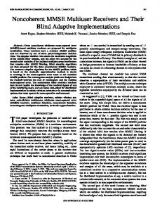
The projection receiver (19) has been simulated extensively using standard convolutional codes from [19]. In the rst experiment, a system using 10 Gold codes (see Appendix B) of length 15 has been tested. A convolutional codes of rate R = 1=2, constraint length � = 5 with 16 states and free Hamming distance dfree = 7 has been used as error control code. Figure 6 shows the performance of one of the users where all users have equal power. The Figure shows simulation results for conventional coded CDMA using error control coding on top, the decorrelator detector using subsequent error control decoding, and our projection receiver with the adjusted metrics. Due to the low cross correlations of the Gold codes, all systems perform well. The second experiment involved using pseudorandom spreading sequences at each bit interval, i.e., the spreading sequences change from bit interval to bit interval for each of the users. These results are also shown in Figure 6. The PR-receiver now clearly outperforms the other detectors. This is a strong supporting result for this detector structure. In fact, it can be shown that the PRreceiver always outperforms the decorrelator, and the two systems have identical performance only for synchronous CDMA using the same spreading sequences in each bit interval. [20]. In [20], the PR receiver is also extended to the case of asynchronous CDMA. The single user performance curves are identical to those obtained by Heller and Jacobs [21] and Odenwalder [22] for additive white Gaussian noise channels. Figure 7 shows the results of these three systems using pseudo-random spreading sequences as a function of the number of users at a signal-to-noise ratio of 6dB. We have chosen a relatively low signal-to-noise ratio for the simulations. For higher SNR values, the di�erences will be larger. Also note that all users have equal power, which is the best case scenario for the matched lter. In the case of unequal powers, it is known that the matched lter performance
PR
0.0001
1e-05
SU
1
2
3
4
5
6
7
8
9
10
K
Fig. 7. Performance results of the PR-receiver, the decorrelator and the correlation detector (MF) as a function of the number of active users in the system.
VI. CONCLUSIONS
We have presented a novel multi-user detector for coded CDMA-type systems. This detector operates by projecting the received signals onto the space which is orthogonal to the unwanted interferers. This produces adjusted metrics for the error control codes used for each user, and also makes this detector near-far resistant. We have also
outlined an adaptive implementation structure for the proposed receiver which is based on the RLS estimation algorithm. Simulations show that the performance of the PR is better than any other coded system proposed to date with comparable complexity, and that the receiver achieves near-optimal performance for systems with low crosscorrelations between the users, such as a system using Gold codes. The general approach presented in this paper can be used to extend the PR-receiver to other cases, for example, to the case where more than one user is decoded by a joint error control decoder, or to the case of asynchronous CDMA. These topics are currently under investigation. APPENDIX A: GEOMETRIC CONCEPTS
Let S � Rn be a k-dimensional subspace of the ndimensional Euclidean space Rn . If the columns of a matrix V = [v1; � � � ; vk ] form an orthonormal basis for S , then we say that S = spanfv1; � � � ; vk g, where span(�) generates all possible linear combinations of the vectors v i, i.e., spanfv1; � � � ; vk g =
(X i
)
i vi j i 2 R :
and
� �,1 P ? = I , LA AT A AT LT
is the projection onto S ? under the metric < x; y >= xT R,1y, which is the one used in Section 3.1. APPENDIX B: GOLD CODES
Gold [6] proved that certain pairs of m sequences of length N exhibit a three-valued cross-correlation function with values f,1; ,t(m); t(m) , 2g, where � (m+1)=2 t(m) = 2(m+2)=2 + 1 m odd 2 + 1 m even These two m sequences are called preferred sequences. From a pair of preferred sequences, say a=[a1a2 � � � aN ] and b=[b1b2 � � � bN ], we can construct a set of sequences of length N by taking the modulo-2 sum of a with the N cyclically shifted versions of b or vice versa. Thus we can obtain N new periodic sequences with period N = 2m , 1. We also include the original sequences a and b and, thus, we have a total of N + 2 sequences. The N + 2 sequences constructed in this manner are called Gold sequences. In our simulations, a total of 10 Gold Codes of length 15 are generated by two polynomials ( m sequences a and b ) with parameters a=[1 1 1 1 1] and b=[1 0 1 1 1] respectively. Let code #1 be m sequence b, code #i ( i=2, � � �, 16) is produced by adding ( modulo 2 ) m sequence b with m sequence a cyclically shifted by (i , 2) position. Code # 17 is m sequence a. The signature sequences used in the 10-user system are the codes #1 to #10, since they produce a maximum value of f11 (top left entry in F ).
The remarkable result is that the matrix P = V V T; is the unique orthogonal projection onto S , i.e., if x 2 Rn, then Px 2 S and kx , Pxk2 is minimal. Further (I , P )x 2 S ? , where S ? is the orthogonal complement of S , de ned as S ? = �y 2 RnjyT x = 0 8 x 2 S : We can consider the projection of x to consist of two parts: References First V T x is calculated, i.e., x is projected onto the rowspace of V . This amounts to computing the inner product [1] N.J. Boucher, Handbook for Cellular Communications, Second of x with each of the vectors de ning the subspace. The Edition, Quantum Publishing, Mendicino, CA, 1992. scalars returned by these inner products are a measure of [2] January issue, IEEE Communications Magazine, 1995. M. Mouly and M-B. Pautet, The GSM System for Mobile Comthe component of x in the direction of vi . Speci cally, we [3] munications , sold by the authors, ISBN 2-9507190-0-7, 1992. have calclated the coordinates of the projected version of [4] Qualcomm Inc., Proposed EIA/TIA Wideband Spread Specx. The second part of the projection is multiplication with trum Standard, Document Number: 80-7814 Rev - DCR 03567, V . We can interpret this process as the construction of the [5] 1992. D.V. Sarwate, M.B. Pursley, \Crosscorrelation Properties of projected version of x form its co-ordinates in S . It is here Pseudorandom and Related Sequences," Proc. IEEE, vol. 68, that we require the vectors vi to be orthonormal. pp. 593-619, May 1980. R. Gold, \Optimal Binary Sequences for Spread Spectrum MulIf the basis of S , say A, is not orthonormal, we pro- [6] tiplexing," IEEE Trans. Inform. Theory, vol. IT-13, pp. 619ceed to orthogonalize A rst via the Gram-Schmidt pro621, Oct. 1967. cedure [15], which gives LA = QT , where L acts as the [7] S. Verd�u, \Minimum Probability of Error for Asynchronous Gaussian Multiple-Access Channels," IEEE Trans. Inform. square root of the metric kernel, i.e., the metrics (or invol. IT-32, pp. 85-96, Jan. 1986. , 1 T ner products) are measured as < x; y >= x R y and [8] Theory, P. Alexander, L. Rasmussen, and C. Schlegel, \A Class of R,1 = LT L. The matrixTT is upper right triangular and Linear Multi-User Receivers,", submitted to IEEE Trans. Inform. Theory, November 1995. Q is orthonormal, i.e., Q Q = I . The projection matrix [9] P. Jung and J. Blanz, \Joint Detection with Coherent Receiver T , 1 P = QQ now, which, using Q = LAT becomes Antenna Diversity in CDMA Mobile Radio Systems", submitted to IEEE Trans. Veh. Techn., September 1993. P = QQT = LAT ,1 ,T ,1�T AT LT : [10] R. Lupas, S. Verd�u, \Linear Multiuser Detectors for Synchronous Code-Division Multiple-Access Channels," IEEE Trans. Inform. Theory, vol. IT-35, pp. 123-136, Jan. 1989. But from AT A = T T QT QT = T T T we obtain
P = LA
�
�,1 AT A AT LT ;
[11] P. Hoher, \A Statistical Discrete-Time Model for the WSSUS Multipath Channel," IEEE Trans. Veh. Technol., vol. VT-41, No. 4, November 1992.
[12] R. Lupas, S. Verd�u, \Near-Far Resistance of Multiuser Detectors in Asynchronous Channels", IEEE Trans. Commun., vol. COM-38, No. 4, pp. 496{508, April 1990. [13] A. Duel-Hallen, \Decorrelating decision-feedback multiuser detector for synchronous code-division multiple access channel," IEEE Trans. Commun., vol. COM-41, pp. 285-290, February 1993. [14] S. Verd�u, \Computation Complexity of Multiuser Detection," Algorithmica, vol. 4, pp. 303-312, 1989. [15] G. Strang, Linear Algebra and its Applications, Harcourt Brace Jovanovich, San Diego, 1988. [16] D.-S. Chen and S. Roy, \An Adaptive Multi-user Receiver for CDMA Systems," J. Sel. Areas Comm., vol. 12, no. 5, June 1994, pp. 808-816. [17] L. Wei and C. Schlegel, \Synchronous DS-SSMA with improved decorrelating decision-feedback multiuser detection," IEEE Trans. Veh. Technol., vol. VT-43, No. 3, August 1994. [18] P. Strobach, Linear Prediction Theory: A Mathematical Basis for Adaptive Systems, Springer, New York, 1990. [19] Shu Lin and Daniel J. Costello, Jr., Error Control Coding: Fundamentals and Applications, Prentice Hall, Inc., Englewood Cli�s, N.J., 1983. [20] P. Alexander, L. Rasmussen, and C. Schlegel, \A Class of Linear Multi-User Receivers," submitted to IEEE Trans. Inform. Theory, December 1995. [21] J.A. Heller and J.M. Jacobs, \Viterbi Detection for Satellite and Space Communications", IEEE Trans. Commun. Technol., COM-19, pp. 835{848, October 1971. [22] J.P. Odenwalder, \Optimal Decoding of Convolutional Codes", Ph.D. thesis, University of California, LA, 1970.
Christian Schlegel (S'86 { M'89) was born in St. Gallen, Switzerland, on August 22, 1959. He received the Dipl. El. Ing. ETH degree from the Federal Institute of Technology, Zurich, in 1984, and the M.S. and Ph.D. degrees in electrical engineering from the University of Notre Dame, Notre Dame, IN, in 1986 and 1988, respectively. In 1988 he joined the CommunicationsGroup at the research center of Asea Brown Boveri, Ltd., in Baden, Switzerland, where he was involved in mobile communications research. He spent the 1991/92 academic year as Visiting Assistant Professor at the University of Hawaii at Manoa, Hawaii, before joining the Digital Communications Group at the University of South Australia in Adelaide, Australia, where he supervised research in mobile communications. Since 1994 he has been with the University of Texas at San Antonio. His interests are in the area of digital communications, coded modulation, mobile radio and multiple access communications. He recently completed his research monograph \Trellis Coding" published by IEEE Press in 1996. Dr. Schlegel is a member of the IEEE Information Theory and Communication Societies. In the past he has organized conference sessions and served as consultant on digital communications and error control coding projects. Sumit Roy received the B. Tech. degree from the Indian Institute of
Technology (Kanpur) in 1983, and the M.S. and Ph. D. degrees from the University of California (Santa Barbara), all in Electrical Engineering in 1985 and 1988 respectively, as well as an M. A. in Statistics and Applied Probability in 1988. During 1988-1994, he served as an Assistant Professor at the Moore School of Electrical Engineering, University of Pennsylvania, and is currently an Associate Professor at the University of Texas at San Antonio. His research interests lie in the areas of communication theory and analysis/evaluation of digital communication systems, with a focus on mobile and multimediawireless networks. He has served as consultant and research investigator on system design aspects of digital television/cable delivery systems, and is currently investigating several aspects of multi-user system design in spread-spectrum networks including joint transmit/receive optimization, interference cancellationreceivers, multi-ratecommunications and fast simulation techniques. He is professionally active in the IEEE Communications Society including membership of several technical committees and currently serves on the Technical Program Committee for ICC96.
Paul Alexander Paul D. Alexander receivedis B.E. and M.Eng.Sc. degrees from the University of Adelaide, South Australia in 1991 and 1995 respectively. Since 1993 he has been studying for a Ph.D at the University of South Australia in the Mobile Communication Research Centre. His research interests including multiuser communication theory in general and multiuser CDMA systems speci cally.
Zeng-Jun Xiang (S'89 { M'92) received his B. Eng. degree and
the M. Eng. degree in telecommunications from Southeast University, formerly Nanjing Institute of Technology, Nanjing, China, in 1985 and 1988 respectively. He began participation in the Joint Doctoral Program between Southeast University (China) and Concordia University (Canada) in 1988 where he received his Ph.D degree in telecommunications in 1992. After receiving his Ph.D degree, Dr. Xiang joined the National Communications Laboratory at Southeast University as Assistant Professor and Vice Director of the Communications Research and Teaching Group. From 1993 - 94, Dr. Xiang worked as a Post Doctoral Fellow in the Center for Signal Processing and Communications, Concordia University. He joined the Coding, Communications and Control Laboratory at The University of Texas at San Antonio in August 1994 as a Research Scientist and Lecturer. Since February 1995, he has been with INRS-Telecommunications, Canada, as a Research Associate and working in the area of indoor wireless personal communications services(PCS) systems. Dr. Xiang was the Chairman of the IEEE Southeast University Student Branch from 1990 to 1991. He has published over 40 papers in recent years. His research interests include: wireless PCS, CDMA, and adaptive signal processing in communications.