Two degree of freedom fast steering mirror (FSM) with flexure suspension, ... The mirror is suspended on a flexure mount and its x and y axis can be separately ...
Multi-worm tracking using superposition of merit functions Linda Ivonne Rivera, Benjamin Potsaid and John Ting-Yung Wen Center for Automation Technologies and Systems, Rensselaer Polytechnic Institute, Troy NY, USA ABSTRACT Traditional solutions for long term imaging of living small biological specimens and microorganisms lack efficiency due to computationally expensive algorithms, and field of view limitations in optical microscopes. This paper describes a new algorithm that allows for real time tracking of multiple 1mm nematodes called Caenorhabditis elegans with a novel optical microscope design called the Adaptive Scanning Optical Microscope (ASOM), developed at the Center for Automation Technologies and Systems (CATS). Based on the real time experimentation, an improved algorithm to track multiple worms in the presence of entanglements is generated. The stages of this development start with an enhanced digital motion controller for the ASOM high speed scanning mirror to suppress undesired vibrations that limit the system capacity to track multiple organisms. The second phase is the integration of the ASOM apparatus, the high speed motion control, and a base tracking algorithm, all which allows for rapid image acquisition to track multiple C. elegans in real time. The base algorithm was developed at CATS and has been proven to track a single C. elegans in real time. Results demonstrating the efficacy of the complete system are presented. Lastly, an enhanced tracking algorithm is described that shows improved accuracy and robustness in tracking worms even when they become entangled. Taking into account the unique ASOM design, individual segments of the worm are tracked throughout an image sequence, and a mosaic pattern covering the entire worm is subsequently created. The algorithm takes advantage of geometric and dynamic knowledge of the C. elegans such as size, and movement patterns. The enhanced algorithm is tested on previously recorded footage. Simulated tracking experiments also illustrate the effectiveness of the enhanced algorithm and are presented. Keywords: Worm tracking; C. elegans; ASOM; Feedforward control
1. INTRODUCTION The ability to track single cells, organisms, animals and populations simultaneously in real time is a critical, yet difficult goal to achieve. Biologists and neuroscientists are particularly interested in observing the behavior of the Caenorhabditis elegans worm. This free-living roundworm of approximately one millimeter in length, is an attractive specimen of study since it is multicellular eukaryotic, and has one of the simplest body architectures with a nervous system. At the same time, the complete cell lineage is known1,2 and the synaptic connectivity of the nervous system has been completely mapped by serial section electron microscopy.3 Therefore, the C. elegans worm is used extensively for developmental, genetic, and behavioral studies. Having many of the essential attributes of higher life forms,4 it is also a convenient model system to extrapolate fundamental findings to human beings. Furthermore, the C. elegans small size and transparency at all life-cycle stages makes it ideal for microscopy-based analysis.5 Two of the key challenges to track C. elegans in real time are: the wellknown trade-off between the resolution and field of view in optical microscopes, and computationally expensive algorithms inadequate for real time implementation. Common solutions aiming to solve the small field of view problem include, supplementing the microscope with multiple parfocal objectives on a rotating turret, moving stages, zoom microscope designs, among others.4 These methods however, exhibit deficiencies in practice. Using multiple parfocal objectives or a zoom microscope design does not allow for a wide field of view and high resolution simultaneously. A moving stage causes inevitable agitation to the specimen as well as relatively slow dynamic performance.4 An innovative solution to this problem is the Adaptive Scanning Optical Microscope (ASOM), developed at the Center for Automation Technologies and Systems (CATS). This novel design facilitates challenging spatial-temporal observations and offers a unique set of performance capabilities compared with the existing wide field imaging technologies.4 The ASOM design
Optomechatronic Technologies 2008, Otani, Bellouard, Wen, Hodko, Katagiri, Kassegne, Kofman, Kaneko, Perez, Coquin, Kaynak, Cho, Fukuda, Yi, Janabi-Sharifi, Eds., Proc. of SPIE Vol. 7266, 72661C • © 2008 SPIE • CCC code: 0277-786X/08/$18 • doi: 10.1117/12.816468 Proc. of SPIE Vol. 7266 72661C-1
allows observation over a large field while preserving the quality of the image, which in turn permits examination of specimens without agitating their natural states. Manual imaging of multiple and freely moving C.elgans has been demonstrated with the ASOM,6 and more recently, a base algorithm developed at CATS was implemented to automatically track a single C. elgans worm. This base algorithm is appropriate for real time implementation and takes in account unique ASOM features. Nevertheless, to achieve robust real time tracking of multiple worms with the ASOM, two main obstacles exist: • Undesired vibrations present in the ASOM steering mirror. • Inability of the base algorithm to resolve worm entanglements. This paper presents a solution to the first obstacle by augmenting the digital motion control of the steering mirror with a feedforward controller to decrease settling times. The high speed motion control is then integrated with a low cost ASOM prototype and previously developed image processing algorithm to demonstrate real time tracking of multiple worms. The second obstacle is overcome by generating an enhanced algorithm based on the experience gained from real time testing, and which takes into account intrinsic geometric and dynamic features of the C. elegans.
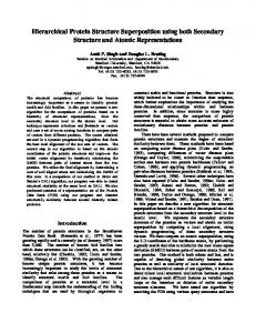
2. ASOM: EXPERIMENTAL TESTBED To effectively expand the field of view while preserving high resolution, the ASOM design uses a MEMS deformable mirror in synchronization with a high speed steering mirror, and a specially designed scanner lens. The basic concept, shown in Figure 1 (a), is to create a post-objective scanning configuration by placing the steering mirror in between the scanning lens and the imaging optics. This arrangement allows to quickly scan a k × k pixel sub-field by acquiring an image at each position. Therefore, regions in the workspace can be imaged as disjoint or overlapping image tiles, which can then be assembled to form a large continuous virtual image, as illustrated in Figure 1 (b). Figure 2 shows a realistic ASOM layout. The process of acquiring an image starts by 45o
steering mirror 39.4o
35.5o
To imaging optics and camera
(b)
ASOM sub-field scanning tracking moving object in time
rare event detection
(a) k x k pixel sub field of view
full area coverage imaging only region of interest
(0.0,0.0mm)
(-12.2,0.0mm)
(-20.3,0.0mm)
Sub field of view in both images is larger than true scale for illustrative purposes
Figure 1. (a) ASOM post objective scanning design (b) ASOM modes of operation
illuminating the object of interest. The light from the object is collected by the scanner lens assembly to form a converging beam, which is then aimed to the two degree of freedom steering mirror. The angle of the steering mirror defines the center of the field of view on the object. A downside of the scanner lens is that it introduces significant wavefront aberrations which cause blurring of the image. This problem is handled by directing the light from the steering mirror to the deformable mirror through a pupil imaging stage. The deformable mirror adapts its surface shape to correct for the wavefront errors. Consequently, the light coming out of the deformable mirror is nearly aberration free. After passing through the pupil relay optics and being projected onto the science camera, the image quality is beyond the diffraction limit indicating that imaging is virtually perfect.7
Proc. of SPIE Vol. 7266 72661C-2
A low cost ASOM prototype built with off the shelf optics is shown in Figure 3. This prototype has been used to prove all essential aspects of the ASOM concept, and it is utilized to perform the experiments described in this paper. The components of this prototype are listed below7 : • Scanning K¨ ohler illumination stage. Due to design sensitivity to chromatic aberration using only BK-7 glass, a 510nm wavelength bandpass filter is included to eliminate light below 500nm and above 520nm. • Telecentric 12 element scanner assembly. • Two degree of freedom fast steering mirror (FSM) with flexure suspension, electromagnetically actuated (Optics in Motion OIM101). • MEMS deformable mirror (Boston Micromachines Mini-DM). This mirror can correct for the wavefront aberrations to within the diffraction limit. It has 32 electrostatic actuators with 400µm actuator spacing, a 2.5µm actuator stroke, and a 2.0mm diameter actively controlled area. The 2.5µm stroke is capable of correcting for up to several waves of aberration, which allows for high image quality even for the off-axis field positions and enables the expanded field of view. • CCD camera (Pulnix TM200). Final imaging optics
Science camera
System aperture
Field lens / pupil imaging optics inverted eye-piece
Steering mirror Deformable mirror
Field lens / pupil imaging optics forward eye-piece
Scanner lens assembly
Scale:
50mm
Object
Figure 2. ASOM preliminary design
Digital Camera Pulnix TM200
—
——
System Aperture
11
Mirror
Scanner Lens \12 element design /using off-the-shelf
Boston Micromachines
Thorlabs 2 inch optics
Object Plane
2X Galvo Steering Mirrors Cambridge Technologies
Scanning Kohler Illumination
Figure 3. Low cost ASOM prototype
Proc. of SPIE Vol. 7266 72661C-3
Experimental Setup
3. PREVIOUS RESEARCH ON C. ELEGANS WORM TRACKING Several methods have been developed to track C. elegans worms. Some methods aim to track one or two worms at high magnification8,9,10 while others perform large-scale automated analysis of entire worm populations.5 Wei et.al 8 demonstrates automatic tracking of a single C. elegans from a video sequence. Using thresholding techniques, the images are segmented to isolate the worm body from the background and remove noise and other undesired components. Next, a thinning algorithm is implemented to extract useful information from the segmented objects. This information is then used to estimate the head and tail segments of the worm. Other techniques like those described in9,10,5 rely on model based algorithms. Fontaine et. al 9 generates a worm model using the geometry of planar curves. A nonlinear estimation of the model’s parameters is performed using a central difference Kalman filter (CDKF). This filter is then expanded to track two worms and detect worm occlusions. Instead of planar curves, Huang et. al 10 creates an articulated worm model with N rectangular blocks, arranged in a deformable configuration. The blocks are attached by a spring-like connection between adjacent parts, which may or may not coincide. Each block position is defined by parameters (x,y,θ), which specify the center coordinate and the part orientation. The collection of all (x,y,θ) for each block is referred to as a worm body pose. Roussel et. al 5 develops a model that attempts to capture both the structure and dynamics of the C. elegans in a decoupled way, and uses a recursive Bayesian filter to perform the tracking. The worm shape is related to its stable features such as width profile, length and body orientation. Worm movements are expressed in terms of three primitive patterns, peristaltic progression, deformation, and translation. These techniques however, have several deficiencies. A drawback, common to all the methods is that they have only been efficiently proven during post-processing. At the same time, procedures that can track multiple worms at high resolution have been demonstrated for at most two worms. Moreover, high resolution methods face the obstacle of specimens going out of the field of view due to limitations in the optical microscope. Common ways to maintain the worm within viewing range include using a moving stage8,10 or partially immobilizing the worm to facilitate tracking.9 However, these forms of agitation to the organism can significantly alter its behavior, compromising the validity of the observation results.
4. FAST STEERING MIRROR MOTION CONTROL The two degree of freedom steering mirror is a critical ASOM component when performing multi-worm tracking. The mirror quickly steers to image N regions of the worm until the complete body is visible. To achieve multiple worm tracking, great speed and precision are necessary from the steering mirror in order to reach all N locations for each worm being tracked. The mirror is suspended on a flexure mount and its x and y axis can be separately controlled. In previous work, a digital controller was designed to decrease the long settling times and steady state error that resulted from using a stock analog controller. The digital controller was developed using xPC target from the MathWorks as the realtime operating system and MATLAB/Simulink as the development environment. The controller was obtained by first identifying the spring constant of the flexure mount and using feedback to cancel out the disturbance. Then, a proportional lead controller was designed based on the identified dynamic system model.7 However, the feedback controller is not enough to suppress undesired vibrations in the mirror. Therefore, the digital control for each axis is augmented with a feedforward controller based on a FIR filter to approximately invert the closed loop dynamics. The development scheme for this controller is that proposed in,11 where the identified model is used to design an inverse dynamics feedforward controller. Iterative learning is performed to refine the feedforward control signal based on the output tracking error. The coefficients of the FIR filter are obtained using a fit to results from Iterative Learning Control (ILC).7 The performance of the augmented controller was evaluated by generating random x y move trajectories to perform coordinated moves with the mirror. The realtime control ran at a 0.15ms sample rate. The dynamic response of the steering mirror system performing coordinated x y moves for a range of move lengths is presented in.7 Results indicated that this system should be able to achieve at least 100 frames per second during realtime operation. The camera used in the initial ASOM prototype system is limited to 30 frames per second.7
Proc. of SPIE Vol. 7266 72661C-4
A follow-on prototype of the ASOM that is currently being developed integrates a high speed camera using the Camera Link data transfer interface to achieve 100 frames per second7 and is equipped with a 3 inch steering mirror.
5. WORM TRACKING ALGORITHM DEVELOPMENT 5.1. Base Algorithm The base algorithm was originally developed at the Center for Automation Technologies and Systems (CATS) with the purpose to show that real time tracking with the ASOM is a tangible idea. It relies heavily on inherent geometric and dynamic traits of the C. elegans. Three key aspects that are taken into account are: type of movements exhibited by the worm,5 intensity of movement in different regions of the body, and worm orientation. The theme that emerges throughout the development is that by cleverly incorporating the intrinsic traits of the C. elegans in the tracking algorithm, it is possible to keep track of its movement. This gives rise to the concept of “Merit Functions.” Each constraint, given by an intrinsic attribute of the worm can be represented as a distinct function. The premise is that by superimposing these functions, the search region can be minimized to effectively track the worm throughout a given workspace. A high resolution image of the C. elegans is not acquired by a single frame with the ASOM, therefore N regions are necessary to cover the entire worm. Through observation of worm footage, it was established that N = 3 tiles, 480 × 640 pixels in size, is the minimum number required to cover the the entire body of small to medium size worms. Each of the tiles is an individual image frame displaying the three main regions of the worm body namely, head, mid, and tail. The head and tail region exhibit dynamic characteristics different to the mid section, therefore tracking techniques for head and tail differ from the mid section methods. To track the head and the tail the following merit functions are defined: • The image difference: detects movement of the head and tail by subtracting previous and current images. • The vector projection: estimates possible end points of the worm by calculating projections onto the previous worm orientation vector. The general mid section tracking is performed as follows: • The displacement that takes place in the mid section frame, is estimated based on head and tail position updates. • The known mid position is shifted by the amount of the estimated displacement and a line search is performed to find the new mid position. 5.1.1. Image Difference The main objective of the image difference function is to reveal the locations in a region S, within the image difference, that exhibit the greatest movement; region S is depicted in Figure 4 as a square space centered in the image difference. The greatest movement is detected as follows: 1. Within the selected region S, pixel points pij are analyzed by performing a n × n sampling every m pixels. 2. The sampled values at every pij location are added as shown in the equation below f1 = pi−n,j−n + pi−n,j + pi−n,j+n + pi,j−n + pi,j+n + pij + pi+n,j−n + pi+n,j + pi+n,j+n ,
(1)
where f1 is considered as the degree of movement associated with position pij . 3. As the absolute value of f1 increases the degree of movement also increases. Therefore, larger values of |f1 | are favored. A movement threshold value Td is established. If the value of |f1 | is below Td , the position pij associated with f1 is eliminated as a potential position update.
Proc. of SPIE Vol. 7266 72661C-5
4. The position pij within S that corresponds to the largest value of |f1 | is selected as the position update pijupdate . Experiments showed that tracking worms with the image difference function f1 alone, is not sufficient. Due to drastic worm movements, the maximum value of |f1 | can be found at a position pij that is far away from the actual location of the head or tail. This error can quickly propagate to other frames, subsequently causing tracking failures. Therefore, another constraint that helps to minimize the error is necessary. 5.1.2. Vector Projection The worm tends to move back and forth along its spine axis, and drastic changes of position in the direction perpendicular to this axis are not expected. At the same time, even though the ends of the worm exhibit rapid deformations that produce localized changes in direction, the overall orientation of the worm body does not vary drastically from frame to frame. Given these assumptions, the second condition for tracking uses orientation information based on previous position data to estimate the ends of the worm. Steps for this procedure are as follows: −→ from the center of head and mp 1. After f1 is calculated, and the search region S is established, vectors − ij −→, among the set that is tail frames to the pixel points pij are calculated. Figure 4 shows a few vectors − mp ij calculated for a given head image difference. VectorProjection J
/1
Figure 4. Vectors mp � ij for a given set of positions pij
/
Figure 5. Vector projections onto me � for a given set of vectors mp � ij
−→ is then projected onto the previous mid to head or mid to tail vector − → as shown below 2. − mp me, ij −→ · − → f2 = − mp ij me.
(2)
Values f2 for the vectors in Figure 4, are depicted in Figure 5. 3. The algorithm favors larger vector projections f2 , since they tend to be associated with pixel points pij in close proximity to ends of worm. The vector projection f2 acts effectively as a force pulling away from the → body in the direction of − me 4. The position pij within S that corresponds to the largest value of f2 is selected as the position update pijupdate .
Proc. of SPIE Vol. 7266 72661C-6
5.1.3. Mid Section Tracking Once optimal head and tail positions are known, the mid section position is estimated. This region of the worm body is primarily characterized by curvilinear translations along the worm spine axis (peristaltic progression5). Therefore, less intense and evenly distributed movement is expected in this image frame. At the same time, worm images in general are characterized by low intensity values depicting the body of the worm and high intensity values depicting the background. Thus, it is possible to estimate the mid section update by finding the correct low intensity value on the worm. To achieve this, it becomes essential to gain knowledge about the worm orientation. The procedure is as follows: → − 1. A line search, orthogonal to the vector from tail to head th, is performed in order to intersect the body of the worm. Positions pij along the line with low intensity values I are favored. 2. I is updated until the lowest intensity value Imin is found. The position pij associated with Imin is selected as the mid position update mupdate .
5.2. Enhanced Algorithm The base algorithm described in the previous section has been proven to successfully track a single C. elegans worm in real time, and in this paper we show that it can be expanded to track multiple worms. However, the algorithm has a number of deficiencies, as outlined below: 1. The most prominent is the lack of a mechanism that can track worms accurately as they become entangled with each other, which is a common occurrence among C. elegans. 2. Another, is mid section tracking failure caused by background artifacts with similar intensity values as the worm, that can be mistaken by an actual worm when performing the line search. 3. In terms of the worm mosaic, the major issue is the lack of complete body coverage that arises when dealing with larger worms. 4. Other less frequent sources of tracking failure include unusual motion behavior of the worm, and instances of rapid drastic movement. The enhanced algorithm seeks to effectively address drawbacks 1. through 3. while preserving the tracking success achieved by the base algorithm. To achieve this goal, specific scenarios from previously acquired data are explored to clearly identify the reasons of tracking failure. Throughout this process other characteristics about the worm are recognized and become the basis of two additional merit functions for head and tail tracking: 1. The length constraint: eliminates inaccurate position candidates based on the assumption that the worm length undergoes very small changes from frame to frame. 2. The angle constraint: provides additional filtering of wrong position estimates based on the assumption that the overall orientation of the worm undergoes small changes from frame to frame. The augmented algorithm, as opposed to the base algorithm requires the knowledge of the mid section before the head and tail updates can be estimated. To achieve this, a cubic line interpolation in the mid image is used to establish possible mid position updates. Additionally, to improve the success of line searches in the mid section, the assumption that the worm is not expected to move in the direction orthogonal to its spine axis is used to constraint the search.
Proc. of SPIE Vol. 7266 72661C-7
5.2.1. Length Constraint Experiments performed on various successful tracking sequences, measured the average change in worm length from frame to frame. These experiments revealed that for short periods of time, the length of the worm undergoes very small changes, and it can even be assumed to be constant provided a precise length measurement technique is available. Since the worm length in this algorithm is calculated based on vectors, which do not precisely fit the spline like body of the worm, it is necessary to keep track of changes in length from frame to frame. Even though we cannot assume a constant length, a length constraint can still be established as another criterion in the calculation of position updates. Given this assumption, the length constraint merit function is introduced to the algorithm using the following steps: 1. First, a model length lmodel is defined based on the previous position information of the worm. For each worm being tracked two length models are established, one measured from mid to head and one from mid to tail; each model is used for head and tail tracking respectively. 2. The lengths lpij , measured from possible mid candidates to positions pij , within the search region S , are compared to lmodel as follows f3 = lmodel − lpij . (3) 3. The difference value |f3 | between these lengths is expected to be small, therefore a threshold value Tl is established. If |f3 | is above Tl , then the position pij associated with f3 is eliminated as a potential position candidate. 4. f3 defines the length constraint merit function. Even though the length constraint is able to resolve several cases of worm collisions, there are certain scenarios in which tracking continues to fail. To further constraint the group of position candidates, a forth merit function called the angle constraint is introduced. 5.2.2. Angle Constraint Using the assumption that the orientation of the worm does not vary significantly from frame to frame, the angle constraint function is defined. To incorporate this new merit function, the steps below are followed: 1. First, a model angle Θmodel is defined based on the previous position information of the worm. Θmodel is measured with respect to the horizontal axis of the image frame. For each worm being tracked two angle models are established, one based on the mid to head vector and another based on the mid to tail vector; each model is used for head and tail tracking respectively. 2. Angles Θij , calculated between the horizontal axis and vectors from possible mid candidates to positions pij , within S, are compared to Θmodel as follows f4 = Θmodel − Θij .
(4)
3. The difference value f4 between these angles is expected to be small, therefore a threshold value Ta is established. If f4 exceeds Ta , the position pij associated with f4 is eliminated as a potential position candidate. 4. f4 defines the angle constraint merit function
Proc. of SPIE Vol. 7266 72661C-8
6. SUPERPOSITION OF MERIT FUNCTIONS In order to achieve optimal worm tracking of C.elegans worms before, during and after they come in contact with each other, all four energy functions: image difference, vector projection, length constraint and angle constraint need to be superimposed. Even though their nature is very different, their interaction can be established through another function, which takes into account the contribution of all phenomena. This cost function is defined as follows (5) fe = W1 f1 + W2 f2 + W3 f3 + W4 f4 , where W1 , W2 , W3 and W4 are the weights associated with each function. The goal if to maximize fe maximize fe = W1 f1 + W2 f2 + W3 f3 + W4 f4 ,
(6)
subject to the constraints established for each merit function. When femax is determined, the position pij associated with it is selected as the optimal position update pijupdate .
7. SURFACE PLOTS A way of visualizing the behavior and interaction of the merit functions, is through their surface plots. Each function can be depicted in a three dimensional plane, where the first two dimensions indicate the position within the image frame, and the third dimension is the value of the function at the specified position. Performing this type of analysis allows to visualize the contribution of each function to the overall worm tracking. It also serves as a visual aid when specifying weight values for the cost function fe . For the example shown in Figure 6, the first two images are the image subtraction from a pair of previous and current head images, with the second one emphasizing the search region S. The 3D plots offer two views of the overall cost function surface with appropriate values for W1 , W2 , W3 , W4 . These plots show that by superimposing all of the functions, the “pool” of position candidates is further constrained. Here we observe how the areas of no interest lose value, while the regions where the worm head (femax ) is located become more prominent.
Figure 6. Cost function surface plot example
8. SIMULATED AND EXPERIMENTAL RESULTS 8.1. Real Time Tracking of Multiple Worms Real time worm tracking was performed successfully with a total of three worms using the experimental set-up described in Section 2. The C.elegans worms used were alive and moving on a bacterial lawn supported by an agar medium in a petri dish. A host computer acquired (MATROX Meteor II frame grabber) and processed the images, while a second computer was dedicated for real time control running MATLAB xPC Target, and implemented the digital control/trajectory generation algorithms for the fast steering mirror. The base tracking algorithm was written in C code and expanded to track three worms.
Proc. of SPIE Vol. 7266 72661C-9
Using three tiles to capture the worm body was not sufficient for large worms. This problem was resolved by adding a fourth tile to increase worm coverage. Selected frames from a movie of a successful run can be seen in Figure 7, where Frame 1 shows the first worm that was initialized, Frames 50, 62, 74 show tracking of two worms; Frames 78, 101, 166 and 279 illustrate tracking of three different worms.
Frame 1
Frame 166
Frame 50
Frame 78
Frame 101
Frame 251
Frame 279
Figure 7. Select frames from real time tracking of three worms - 4 tiles
8.2. Simulated Tracking To test the effectiveness of the enhanced algorithm, simulations were performed using the image data from previous experiments where tracking failed. The algorithm was implemented in MATLAB, and applied to five three tile sequences where collisions had occurred. Successful tracking was achieved 80 % of the time. For a given sequence, a comparison of the tracking results from the base and enhanced algorithms is illustrated in Figure 8. This example shows a few frames before and while a collision takes place. The image subtraction images indicate position updates found by the two algorithms, and for selected frames the complete mosaic of the worm being tracked in shown. The mosaic images depict the location where the next image would have been grabbed if the enhanced algorithm was used. This algorithm is able to follow the desired worm while the collisions take place. The enhanced algorithm can only be tested up to the point where a collision happens since there is not any useful image data afterwards. Simulated tracking using four tiles was performed similarly as for three tiles. In this
Proc. of SPIE Vol. 7266 72661C-10
Improved algontlnn
Base algoritlnn
Figure 8. Base algorithm vs. enhanced algorithm example 1
case 6 sequences were evaluated, and the tracking was successful 90 % of the time. The higher rate of success for these experiments is in part attributed to the fact that having four tiles provides a better approximation of the worm length. With four control points instead of three, vectors that better resemble the worm body bending configuration, can be measured.
9. SUMMARY AND CONCLUSIONS This paper presents the integration of the ASOM, high speed motion control and base tracking algorithm to demonstrate real time tracking of three C. elegans worms. This process involves enhancing the digital motion control for the fast steering mirror in the ASOM, from a proportional lead controller to a feedforward controller. At the same time, an improved tracking algorithm aimed to resolve worm entanglements is described, where the concept of merit functions, introduced in the base algorithm, is further explored. To develop this algorithm, previous footage is analyzed to determine tracking failure scenarios and to identify other inherent worm characteristics that could be use to define additional merit functions. As the ASOM is a novel exploration to a multidisciplinary approach for expanding the field of view in optical microscopy, and the algorithm techniques proposed are a new approach to tracking C. elegans, there is still much research and practical work to be done in order to solidify the accuracy of the algorithm, and to expand the tracking to a larger number of specimens. The ideas presented here provide a foundation for future research related work associated with tracking C. elegans with the ASOM apparatus.
ACKNOWLEDGMENTS This material is based in part upon work supported by the National Science Foundation under Grant No. CMS0301827 and by the Center for Automation Technologies and Systems (CATS) under a block grant from the New York State Office of Science, Technology, and Academic Research (NYSTAR). J.W. is also supported in
Proc. of SPIE Vol. 7266 72661C-11
part by the NSFC two-bases project (No. 60440420130), and the Outstanding Overseas Chinese Scholars Fund of Chinese Academy of Sciences (No. 2005-1-11), China.
REFERENCES 1. Sulston, J. E. and Horvitz, H., “Post-embryonic cell lineages of the nematode, Caenorhabditis elegans,” Dev. Biol. 56, 110–156 (1977). 2. Sulston, J. E., Schierenbern, E., White, J. G., and Thomson, J. N., “The embryonic cell lineage of the nematode Caenorhabditis elegans,” Dev. Biol. 100, 64–119 (Nov. 1983). 3. White, J. G., Southgate, E., Thomson, J. N., and Brenner, S., “The structure of the nervous system of the nematode Caenorhabditis elegans,” Phil. Trans. Royal Soc. London. Series B, Biol Scien. 314, 1–340 (1986). 4. Potsaid, B., Finger, F. P., and Wen, J. T., “Living organism imaging with adaptive scanning optical microscope (ASOM),” in [Imaging, Manipulation, and Analysis of Biomolecules, Cells, and Tissues], Proc. SPIE 6441, 64411D (2007). 5. Roussel, N., Morton, C. A., Finger, F. P., and Roysam, B., “A computational model for C. elegans locomotory behavior: application to multiworm tracking,” Biomedical Engineering, IEEE Transactions on 54(10), 1786–1797 (Oct. 2007). 6. Potsaid, B., Wen, J. T., and Finger, F. P., “Automation of challenging spatial-temporal biomedical observations with the adaptive scanning optical microscope (ASOM),” Automation Science and Engineering, 2006. CASE’06 IEEE International Conference on, 39–44 (Oct. 2006). 7. Potsaid, B., Rivera, L. I., and Wen, J. T., “Adaptive scanning optical microscope (ASOM): large field of view and high resolution imaging using a MEMS deformable mirror,” in [MEMS Adaptive Optics], Proceedings of SPIE 6467, 646706 (Feb. 2007). 8. Wei, G., Cosman, P., Berry, C. C., Zhaoyang, F., and Schafer, W. R., “Automatic tracking, feature extraction and classification of C. elegans phenotypes,” Biomedical Engineering, IEEE Transactions on 51(10), 1811– 1820 (Oct. 2004). 9. Fontaine, E., Burdick, J., and Barr, A., “Automated tracking of multiple C. elegans,” Engineering in Medicine and Biology Society, 2006. EMBS’06. 28th Annual International Conference of the IEEE, 3716– 3719 (2006). 10. Huang, K.-M., Cosman, P., and Schafer, W. R., “Automated tracking of multiple C. elegans with articulated models,” in [Biomedical Engineering: From Nano to Macro], 2007. ISBI 2007. 4th IEEE International Symposium on, 1240–1243 (Apr. 2007). 11. Potsaid, B. and Wen, J. T., “High performance motion tracking control,” in [Control Applications], Proceedings of the 2004 IEEE International Conference on 1, 718–723 (2004).
Proc. of SPIE Vol. 7266 72661C-12