Multidisciplinary Design of Flexible Aircraft Haroon Awais Balucha, , and Michel van Toorenb,1 a
Ph.D. Researcher , Faculty of Aerospace Engineering. Prof. Dr., Faculty of Aerospace Engineering.
b
Abstract. The increasing use of fiber composite materials in the design of aircraft structures and the advent of easily available fast personal computers, have forced the aircraft design engineers to adopt complex mathematical models, which usually adress the trio of flight mechanics, aereoalsticity and controls in one simulation. The adoption of such kind of mathematical models also open a door for a robust methodology on the multidisciplinary optimization (MDO) of flexible/aeroelastic aircraft. This paper gives an overview of the a “closed-loop” design framework, which optimizes the structure of any given component like fuselage of the aircraft under dynamic loads. The objective is to reduce the weight of the given structure vis-à-vis maintaining the constraints of structural strength and the dynamic stability of the whole aircraft. An optimization problem is presented in the end, where the fuselage structure of a small executive jet is optimized under strcutural loads due to atmospehric turbulance. Keywords. MDO, design framework, flexible aircrafts, fuselage structure, dynamic loads, minimum weight, stability constraints
1 Introduction The advent of fast and affordable personal computers has opened a new door to implement efficient methodologies of multidisciplinary optimization (MDO), which can easily handle the large problems related to aircraft structural design. Previously the optimization problems are mainly limited to the relatively smaller problems [3, 8, 9], in which the fuselage panels made of fiber composite materials are optimized under static loads conditions. During the panel level optimization, most of the time, the sensitivities of equivalent stiffness of that panel on the overall dynamic response and consequent structural loads of the aircraft are neglected, which do not seem to be a good practice. An optimization process, called “aeroelastic tailoring” of flexible wing and tail sections, normally suggests several different combinations of fiber orientations 1
Prof. Dr., Design of Aircraft and Rottercraft, Faculty of Aerospace Engineering, Delft Univeristy of Technology, Kluyverweg 1, 2629 HS Delft, The Netherlands; Tel: +31 (0) 15 27 84794; Fax: +31 (0) 15 27 89564; Email:
[email protected]; http://www.lr.tudelft.nl/dar
2
Haroon Awais Baluch , and Michel van Tooren
along the webs and skins of the structure. Where the equivalent stiffness of that section or panel is suppose to change in every optimization iteration and that change in the stiffness in turn is also suppose to change the vibration spectra of that component and so are the structural loads. For example, an optimization problem can end up with such a design that can hold generally anisoptropic material properties. With anistropic properties the bending-torsion coupling in a beam like structure under bending loads is quite obvious, whereas the design engineer, most probably, have been provided with the structural loads based on assumption of uncoupled bending-torsion deformations. In such a sconorio the optimization process should include a kind of “closed-loop” framework where the new sets of loads should be calculated for each iteration. The problem is not that simple as it is stated here. The mathematical model which addresses the trio of flight dynamics, aeroelasticity, and the controls of the fully flexible aircraft is quite complex and requires extra care while using in large optimization problems. Especially when the design engineer does not have a pre hand reference on the sensitivity of optimization parameters on the structural loads then the unnecssary calling of loads module in the optimization framework is to be avoided. In this paper we give an overview of a framework [2] that would be applicable for optimizing the flexible aircraft under dynamic loads. Section 2 starts with the discrete representation of a fully flexible aircraft. A brief discussion about the dynamic loads and the mathematical model is also presented in section 2. Section 3 talks about the optimization framework, which is divided into three layers that include the panel level local structural optimization, section level structural optimization and above all the global level optimization which takes care of the aircraft stability, where the mass and stiffness matrices and consequent structural loads are updated in upper most layer. The methodology of structural representations of the fuselage is discussed in this sections. In section 4 an executive aircraft is subjected to dynamic loads due to the gust while the aft portion of the fuselage is optimized with two different concepts of fiber composite panels. Conclusions are made in section 5.
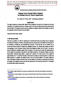
Figure 1. Aerodynamic and Structural Discretization of a Flexible Aircraft
Multidisciplinary Design of Flexible Aircraft
3
2 An Overview of Aircraft Dynamic Model The structure of a flexible aircraft can be discretized into a number of beams. Figure 1 shows a sample aircraft modeled with seven beams to represent fore and aft fuselage structures, one beam per half wing and half horizontal tail, and one beam for the vertical tail, where the aircraft body axes ‘Of’ lies on the juncture of aft and fore fuselages beams. These beams are further discretized into several sections with lumped mass elements ‘mi’ at their mass centers (c.g). These mass elements are attached to each other with springs of average stiffness over the two neighboring sections. For each fuselage beam there are two degrees of freedom (d.o.f) in bending ‘u’ along each ‘y’ and ‘z’ directions of` the aircraft body axes ‘Of’ and one torsion ‘ψ’ along the longitudinal axis of ‘Of’. For each wing and empennage beam there is one bending d.o.f normal to the plane of the lifting surface and one torsion d.o.f. along the reference axis (r.a), i.e. longitudinal axis of their respective coordinate axes at ‘Oi’. The aerodynamic model is presented in the form of several strips with particular lift and drag coefficients. The quasi-steady forces and moments on each strip are the functions of these coefficients and the local angle of attack of the strip. The instantaneous local angle of attack of a strip is a sum of the torsion angle ‘ψ’ of that strip and the rigid-body angle, which includes the aircraft pitch angle at ‘Of’ and the incidence of the lifting surface at its attachment with the fuselage . Dynamic loads are calculated by solving the inertially coupled equations of motion (EoM) [6] of a fully flexible aircraft by using the DARLoads computer code. DARLoads is a software tool for the dynamic loads analysis for the flexible aircrafts, which is being developed by the DAR group of the Faculty of Aerospace Engineering in Delft University [1]. It accepts the aircraft structural and aerodynamics data in the form of local stiffness and lumped mass elements. The aerodynamics data is given in the form of local strips on each lifting surface, where each strip is defined with its particular quasi-steady lifting coefficients. All the component level stiffness, mass and aerodynamic influence coefficients are assembled in the global matrices of the full aircraft, which are then solved in state space form. The aircraft motion is distinguished into rigid body motions with respect to inertial axes on ground, and the elastic motions of aircraft structural components with respect to aircraft body axes. Considering the elastic motions or vibrations about equilibrium state are smaller in magnitude to those of rigid motions, EoM can be written into state-space form and linearized into zero and first-order equations by perturbation theory of extended aeroelasticity [6]:
(
)
(
)
xɺ (0) ( t ) = A(0) x (0) ( t ) + B (0) x (0) ( t ) u (0) ( t )
(1)
The above equation introduces the zero-order state-vector x(0) that represents the rigid body motions i.e. translations and rotations with respect to inertial axes. The control vector, u(0), represents the zero-order control inputs of elevator, aileron, rudder and thrust, respectively. State space matrices A(0) and B(0) represent the
4
Haroon Awais Baluch , and Michel van Tooren
coefficient matrices for inertia and control forces, respectively. During the steadystate flight the zero-order coefficient matrices, A(0) and B(0), remain constant and so is the zero-order state vector x(0)(t). The first-order vector x(1)(t) which takes account of vibrations and their effects on overall response of the aircraft:
(
)
xɺ (1) (t ) = A* + Bx - Bu G x (1) (t ) + Fext (t )
(2)
The state-matrix A* contains the partial derivatives of zero-order velocities, stiffness, and damping matrices with respect to the first-order state-vector. The coefficient matrix Bx gives the sum of aerodynamic and gravitational forces and subsequent moments due to vehicle motion resulting from external disturbance Fext. Bu multiplied by the closed-loop gain matrix G gives the coefficients of forces and moments due to first-order control inputs which consequently minimize the effects of external disturbance. Using the mode displacement method, which is based on the internal elastic forces, the total loads along certain degree of freedom (d.o.f) ‘u’ of a component ‘i’ are expressed as the sum of static loads and time integration of the dynamic loads over the steady state:
0 τ Li( ) = ϕ K i( ) xi(( )) + ∫ xi(1) (t )dt ( ) ( ) 0 u
iu
u
u
u
(3)
where K and φ are the stiffness matrix and vector of mode shapes of the
3 The Optimization Framework The optimization framework is formulated under the domain of the “Analysis Tools” section of the Design and Engineering Engine (DEE), which is a knowledge based engineering (KBE) tool to automate the process of multidisciplinary optimization in aircraft preliminary design [4, 7]. The framework is specifically developed for the structural optimization of a fuselage structure and as for as other components like wings and stabilizers are concerned, a small change in constraint equations and a few design variables can let a design engineer to use the same routine. The algorithm is segregated into three layers, see Figure 2. In which the first or the upper most layer starts with the inputs for the initial conditions of the aircraft, which includes the flight conditions, aerodynamics, and the structural properties of the whole aircraft that also includes the initial structure which is to optimized later on. The initial conditions in the form of structured arrays are then transferred to DARLoads for the dynamic loads analysis. DARLoads gives the output in the form of internal structural loads and deflections of all the components of the aircraft, which are mentioned in section 2.
Multidisciplinary Design of Flexible Aircraft
5
Figure 2. The Optimization Framework
DARLoads is being followed by a while loop, which optimizes the length Ls of a section Ns of the aft fuselage, see Figure 2, where the Ls represents the length between the two adjacent fuselage frames. The while loop begins with a section number and whenever the length Ls of current section Ns is optimized by the use of downstream layers, the Ns is incremented to the next section number. It is supposed that the total length Lf of the aft fuselage is fixed during the preliminary sizing of the aircraft so the condition to enter in the while loop is decided by the sum of all the optimized lengths of the previous sections should not exceed the total length of the aft fuselage, which can also acts a design space for the next section i.e. the upper bound of Ls. The while loop calls the 2nd layer by using the fmincon optimization function in Matlab [5]. Loads in the form of shear forces in three directions and corresponding bending/torsion moments, at the root of the current section, are read from the DARLoads output. A for loop is called afterwards, where each panel in the current section is optimized through the 3rd layer of the algorithm. The length of a for loop depends upon the number of panels considered in a circular section of the fuselage. For e.g. the length of the for loop is 04, if a fuselage is discretized into four panels i.e. crown on the top, keel at the bottom, and two sides [3], but in this paper a fuselage cross-section is discretized into 12 straight panels, see Figure 3. For the turn by turn optimization of each panel, the computer program known as WISST [7] is called in each loop. Depending upon the position of a panel along the circumference of the fuselage, the loads in the 3rd layer are converted into the load intensities of the panel under consideration [2]. Depending upon the panel type i.e. stiffened or sandwiched, WISST first initiates a feasible solution of the
6
Haroon Awais Baluch , and Michel van Tooren
certain width out of the total given width of the panel. Readers are referred to Figure 5 and 6 of Reference 7, where a stiffened panel is depicted in the form of a stiffener and called as a blade element. The failure criteria taken into account are the strength and stability of the blade element. The solution from the initiator is then transferred to the sizing tool, which takes account of the constraints of ply strength and buckling of a full-width panel and meanwhile minimizing the objective of weight per length of the panel. Whenever the objective is achieved the optimized panel is transformed into an equivalent sandwich panel with a fixed skin thickness for each panel along the circumference of the fuselage but with different equivalent material properties of both skin and core i.e. modulus of elasticity/rigidity, poison ratio, and density etc. These equivalent properties are replaced with the new values, till the objective and constraints with respect to the section length Ls are achieved in the 2nd layer of the optimization. Table 1 gives a brief overview of the design variables, constrains, and objectives from local panel to full aft fuselage structural level.
Figure 3. The structural representation of the fuselage
When the upper bound of the design space, as given in the condition to enter in while loop, is exhausted, the equivalent model for each panel is written out in a text file, which includes the bulk data entries of grids and corresponding quad elements with particular equivalent material properties. MSC/Nastran is called on for the static condensation which gives the new stiffness and mass matrices of the aft fuselage, which are then assembled with the rest of the components in global stiffness and mass matrices of the whole aircraft. If the constraint of real and negative eigenvalues of the aft fuselage structure is not achieved then the
Multidisciplinary Design of Flexible Aircraft
7
DARLoads is called on again with the new stiffness and mass matrices, which in turn gives the new sets of loads for the next iteration. Table 1. Optimization variables, constraints and objective Local Panel Level Objective
Constraints
min f ( x )
Global Structural Level
x
WeightPanel f ( x) = Ls
Design variables
Local Section Level
totalPanels
∑ 1
Weight Panels Ls
h = panel height t1 = facing thickness t2 = stiffener thickness n1= facing stacking seq. n2= stiffener stacking seq. w1= stiffener spacing w2= stiffener width Material failure (Tsai-Hill) Skin (facing) buckling loads Stiffener wrinkling loads Panel buckling loads
i = totalSections
∑
WeightSections
1
Ls
i
Ls = section length
Torsion buckling loads
eig(KAF-λMAF) ≤ 0 eig = eigenvalue sol. MAF = mass matrix KAF = stiffness matrix
4 Optimization Example A Twin-jet aircraft is selected as a test case over a discrete gust. To get the initial loads set, the input data required for the structural and aerodynamics properties of the aircraft are taken from the Reference 6. Flight conditions for symmetric flight with the dimensions of the outer geometry of the aft fuselage are given in Reference [2]. After reading the inputs DARLoads assembles all the required matrices. To get the trim condition, DARLoads minimizes the quadric function of rigid-body zero order state vector in Equation (1) and optimizes the control vector for the given speed. The external disturbance in the form of discrete gust is applied for a period of 1 sec, and Equation (2) is numerically solved over a 10 sec. Response of the aircraft in the form of both rigid and elastic motions are recorded and loads along each d.o.f are extracted by using the Equation (6). Figure 4 shows the static loads along the length of the aft fuselage during the trim conditions, where the Figure 5-7 show the dynamic loads at the root section of the fuselage over the time period of simulation. The sign convention for the loads is to be followed with respect to the axes system shown in Figure 3.
8
Haroon Awais Baluch , and Michel van Tooren
Figure 4. Static shear and moments in Z-Y Plane
Figure 5. Dynamic shear and moments in Y-Z plane
Figure 6. Dynamic shear and moments in Z-Y plane
Multidisciplinary Design of Flexible Aircraft
9
Fig. 7 Dynamic torsion moment along X-axis
To start with the structural optimization problem, first the optimization for a foamfilled sandwich fuselage structure is initiated. Material used in the analysis is given in the Table 2. It is thought that a sandwich panels should have a higher buckling strength to that of a stiffened panel so the upper bound of the design variable Ls in the 2nd layer of the optimization is taken same as the while loop condition given in the 1st layer of the optimization. The lower bound is given as 0.1 meters. While using the clockwise direction and starting from the panel 1, as shown in Figure 3, the 2nd layer calls the 3rd layer for the optimization of each panel. Meanwhile the loads sets that are given in Figure 4-7 are integrated by using the Equation (3) and converted to panel load intensities. The length of the first section is optimized at 3.62 meters. Consequently the optimizer suggests only two sections with approximately the same lengths but different weights. The optimized lengths and corresponding weights of the fuselage sections are given in Table 3. Table 2. Material properties
Carbon fiber fabric Flexural modulus, E11 = E22, N-mm-2 Shear modulus, G12, N-mm-2 Poisson ratio, ν12 Density, Kg- mm-3 Foam core Flexural modulus, E11 = E22, N-mm-2 Shear modulus, G12, N-mm-2 Poisson ratio, ν12 Density, Kg- mm-3
45000.0 4000.0 0.03 1.561e-6 75.0 24.0 0.0 52e-9
While keeping in mind the trend of the optimized section lengths in a sandwich structure, the foam-filled stiffened panel optimization is initiated in the second case
10
Haroon Awais Baluch , and Michel van Tooren
with a fixed upper bound i.e. a length of 2.0 meters. The results are pretty much different to those of the first case and the fuselage is optimized into five sections with diverging weights. Table 3 shows the section lengths with their weights per lengths. The section length for each of the second last section is settled at the upper bound. It shows that the analysis could have proceeded further and optimized the section with the larger lengths but the upper bound limited it to the given length. The length of the last section is automatically selected as the remaining portion left out of the sum of the optimized section sizes minus the total length Lf of the fuselage. Table 3. Section lengths and weight comparison
Sec. # Ns
Foam-Filled Sandwich Structure (Case 1) Section Weight Ratio Length Lf, m Kg-m-1
1 2 3 4 5
3.6282 3.4783
Total Weight
238.27 215.6
453.87
Foam-Filled Stiffened Structure (Case 2) Section Weight Ratio Length Lf, m Kg-m-1 1.2237 1.6119 1.8059 2.000 0.465
115.13 66.46 62.79 62.56 32.31 339.25
Now comparing the total weights of both the design concepts i.e. stiffened and sandwich structure. It shows that the foam-filled stiffened panel has an advantage over the sandwich structure. The weight of frames is not included in the design yet, so the weight for the stiffened structure will increase further. However, a practical structural design of the fuselage requires several frames to support the floor and also the connections between the fuselage and wings or tail sections, which make it obvious to include the frames in the sandwich structure too. From this study the only advantage of sandwich structure over the stiffened one appears to be in terms of manufacturing. As stated in Reference 3, the stiffened panels require several manufacturing processes and factory hours, whereas the sandwich panels are easy to manufacture and require less factory hours.
5 Conclusions An attempt is made to formulize an optimization algorithm, which is to be used for the structural optimization in the fuselage design. The algorithm is divided into three layers of optimization, where each layer has its own objective and constraints functions, and design variables. The first layer optimizes the full fuselage structure, while keeping the constraints of negative and real eigenvalue solution of mass and stiffness matrix. The second and third layers take care of section level and panel level optimization, respectively, where the objective is to minimize the ratio of
Multidisciplinary Design of Flexible Aircraft
11
weight per length of a section or a panel. The constraints in this case are buckling and material strength of the concerned fuselage section or the panel. The aft fuselage structure of an executive jet is taken as a test case for the optimization. The structure is designed with two types of concepts i.e. foam-filled sandwich panels and foam-filled stiffened panel. Structural loads sets due to a discrete gust input are created and optimization problem for each concept. The results show that the foam-filled sandwiched structure is quite efficient in terms of panel buckling and cylinder wrinkling, which requires require only one frame over the length of 7.1m of the aft fuselage, whereas the stiffened structure requires at least five to six numbers of frames, where in terms of weight ratio per section length the stiffened structure has an advantage over the sandwiched one, which may not be very practical where a fuselage structure require a quite numbers of frames to hold structures like floor, wings and tail plane. The only advantage of sandwich structure over the stiffened one seems to be in terms of manufacturing.
6 References [1] Baluch HA, Slingerland R, van Tooren MJL. Dynamic Loads Optimization during Atmospheric Turbulence on a Flexible Aircraft. Young Persons Aerodynamic Conference Royal Aeronautical Society Bristol UK October 29-30 2006. [2] Baluch HA, van Tooren MJL, Schut EJ. Design Tradeoffs for Fiber Composite Fuselages under Dynamic Loads using Structural Optimization. 49th AIAA/ASME/ASCE/AHS/ASC Structures, Structural Dynamics, and Material Conference 2008. [3] Jhonson RW, Thomson WL, Wilson RD. Study on utilization of advanced composites in fuselage structures of large transports. NASA 1985; CR-172406. [4] La Rocca, G, van Tooren, MJL. Enabling distributed multidisciplinary design of complex products: a KBE approach. J of Design Research 2007; 5: 1605-1613. [5] Matlab Software Package, Version 7.0 - Release 14, The Mathworks, Natic, MA, USA, 2004. [6] Meirovitch L, Tuzcu I. Control of Flexible Aircraft Executing Time-Dependent Maneuvers. J of Guidance, Control and Dynamics 2005; 28: 1291-1300. [7] Schut EJ, van Tooren MJL. Design “Feasilization” using knowledge-based engineering and optimization techniques. J of Aircraft 2007; 44: 1776-1786. [8] Tuttle ME, Zabinsky, ZB. Methodologies for Optimal Design of Composite Fuselage Crown Panels. Proceedings of the 35th AIAA/ASME/ASCE/AHS/ASC Structures, Structural Dynamics, and Material Conference Apr 18-20, 1994: 1394-1405. [9] Watson JC. AV-8B composite fuselage design. Journal of Aircraft 1986; 19: 235-238.