Thus recycle of catalyst under continuous operation and through ... 3: Bubble sizes in draft tube below the nozzle at different specific power inputs. (P/V).
Multiphase Catalysis In Jetloop-Reactors Arno Behr, M. Becker Technische Universität Dortmund, Department of Biochemical and Chemical Engineering, Chair of Technical Chemistry A, D-44227 Dortmund, Germany Jetloop-reactors are used for a variety of different chemical and biochemical processes as well as waste-water treatment, in which gas-liquid reactions or reactions with suspended solids take place. Their excellent mass-transfer properties and efficiency in dispersing of fluids, comparatively low energy input and ease of construction make them an interesting and in-creasingly important alternative to standard reactor concepts like stirred tanks or bubble columns (Gavrilescu and Macoveanu, 1999, Schügerl, 1980, Stitt, 2002). We for the first time investigated the use of a jetloop reactor in multiphase gas/liquid/liquid reaction systems, especially in hydroaminomethylation reactions (Behr et al., 2000, Behr and Roll, 2005, Zimmermann et al., 1999). In this reaction an olefin, for instance 1-octene (1), reacts in a tandem reaction with carbon monoxide, hydrogen and an amine (2) to yield a hydroaminomethylated product (3) (see Fig. 1). Starting from 1-octene a mixture of linear and branched nonylamines is formed. This reaction can be performed as a gas-liquid reaction using a homogeneous rhodium-phosphine catalyst. However, in this case after the reaction the organic soluble noble metal catalyst and the products are situated in the same liquid phase and a simple separation, for instance via distillation, is not possible because of the thermal decomposition of the catalyst. If the reaction, however, is carried out with a water soluble rhodium catalyst, e.g. with rhodium-triphenylphosphinetrisulfonate (Rh-TPPTS) as catalyst, the reaction can be carried out as a gas/liquid/liquid reaction thus yielding afterwards an organic liquid containing the amine products and an aqueous phase containing the catalyst.
R1
+
R1
HN
N R2
1
[Rh] + CO/2H 2 - H 2O
2
R2
3 for R 1,R2 ≠ H
Fig. 1: Scheme of hydroaminomethylation of 1-octene During intensive investigation on reaction conditions in hydroaminomethylation of 1octene with morpholine conversion up to 90% was achieved in 4 hours with an amine
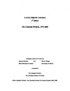
yield of 73%. A major breakthrough was achieved using salts of secondary and primary amines in hydroaminomethylation thus reaching conversion beyond 99% and yields and amine selectivities up to 95 % (Behr et al., 2009). Catalyst leaching to the organic product phase during the experiments was reduced below 2ppm. For upscale of this reaction a jetloop reactor was designed and implemented in a miniplant (Fig. 2). Thus recycle of catalyst under continuous operation and through several recycles can be observed. 1-octene, amine CO / H2
nozzle distillation
settler
c b a
jetloop reactor
product
a = liquid catalyst phase b = liquid product phase c = synthesis gas
Fig. 2: Miniplant for gas/liquid/liquid reaction in jetloop reactor
The reactor consists of a nozzle allocated at the top of the reactor and a draft tube arranged concentrically in the cylindrical reactor body. Mixing and gas induction in jetloop reactors is achieved by a liquid jet flow. The liquid passes the nozzle with high velocity and sucks in gas dispersing it into fine bubbles. This high velocity gas-liquid jet enters the reactor through the draft tube and induces an internal circulation which is further increased by the ascending gas bubbles in the riser section. Hereby the gas holdup is increased which increases interfacial areas and mass transfer (Zehner and Kraume, 2007, Zehner et al., 2000). As geometrical parameters, like draft tube diameter, nozzle diameter and position of the nozzle relative to the draft tube significantly influence operation performance of jetloop reactors (Räbiger, 1988), these were examined in detail (Behr et al., 2008) to guarantee optimum operation conditions in future investigations.
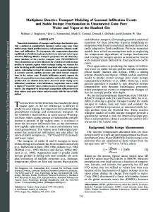
a
b
P/V = 1,1 kW/m3 c
P/V = 3,6 kW/m3 d
P/V = 9,6 kW/m3
P/V = 15,5 kW/m 3
Fig. 3: Bubble sizes in draft tube below the nozzle at different specific power inputs (P/V)
Additionally bubble sizes were analyzed at different positions in the reactor (see Fig. 3) and overall interfacial areas determined. The use of additives like isopropanol or the catalyst system Rh-TPPTS itself resulted in a further decrease of bubble sizes. The introduction of a second liquid phase like 1-octene as used in the hydroaminomethylation described before results in an immense increase of interfacial areas over two magnitudes allowing for optimal reaction conditions in aqueous biphasic hydroaminomethylation (Behr et al., 2009). Following investigations also showed a significant increase of mass transfer from gas to liquid phase up to kLa = 0,8 s-1 when using a second organic liquid phase. Hereby also the specific energy used to create the interfacial areas and high mass transfer is decreasing. When examining residence time distributions of the reactor the part of the reactor responsible for mixing could be identified by simulation in Matlab (Mathworks, 2007). The reactor was represented by a combination of stirred tanks and plug flow reactors in a cell model. The experimental residence time distributions could be reproduced by this model showing an intensive mixing of the liquid phase in the riser section of the jetloop reactor (Behr et al., 2008) due to induced turbulence in the wake of the rising bubbles (Brücker, 1999, Lindken and Merzkirch, 2000). Finally the hydroaminomethylation was successfully transferred into the jetloop reactor proving the successful application of a jetloop reactor in gas/liquid/liquid homogeneous multiphase catalysis. It was shown that an efficient alternative to conventional reactors can be realised using a jetloop reactor with additional benefits in ease of construction, applicability in high pressure reactions, simplified scale up and heat removal.
References Behr A., Becker M. and Dostal J., 2009, Chem. Eng. Sci., (submitted). Behr A., Becker M., Dostal J. and Kohlmann D., 2008, Chem. Ing. Tech., 80, 1501 1508. Behr A., Becker M. and Reyer S., 2009, J. Organometal. Chem., (submitted). Behr A., Fiene M., Buß C. and Eilbracht P., 2000, Eur. J. Lip. Sci. Tech., 102, 467 471. Behr A. and Roll R., 2005, J. Mol. Cat. A: Chemical, 239, 180 - 184. Brücker C., 1999, Phys. Fluids, 11, 1781 - 1796. Gavrilescu M. and Macoveanu M., 1999, Acta Biotech., 19, 111 - 145. Lindken R. and Merzkirch W., 2000, Exp. Fluids, [Suppl.], S194 - S201. Mathworks, 2007, Matlab 7.4, Natick, Massachusetts. Räbiger N., 1988, Hydrodynamik und Stoffaustausch in strahlangetriebenen Schlaufenreaktoren, Verlag TÜV Rheinland GmbH, Köln. Schügerl K., 1980, Chem. Ing. Tech., 52, 951 - 965. Stitt E. H., 2002, Chem. Eng. J., 90, 47 - 60. Ullmann's Encyclopedia of Industrial Chemistry, 2007, 7th edition (electronic release) ed., Wiley-VCH. Zehner P., Ulonska A. and Paciello R., AG B., 2000, Verfahren zur Herstellung von Aldehyden und/oder Alkoholen oder Aminen, DE 198 36 807 A1 Zimmermann B., Herwig J. and Beller M., 1999, Angew. Chem., 111, 2515 - 2518.