Multiple Enhanced Self-protected Spanning Trees Based Architecture for Recovery from Single Failure in Metro Ethernet Yong Li, Wentao Chen, Depeng Jin1, Li Su, Lieguang Zeng State Key Laboratory on Microwave and Digital Communications Tsinghua National Laboratory for Information Science and Technology Department of Electronic Engineering, Tsinghua University, Beijing 100084, China ABSTRACT Carriers and service providers are rushing to provide Ethernet-based virtual private network services in metro area network (MAN) as the most cost effective way to address the needs of the enterprise network market. To address the fast recovery from any signal failure issue in the Metro Ethernet, we propose a metro Ethernet architecture based on multiple Enhanced Self-protected Spanning Trees (ESST). The recovery mechanism, named Birthday-based Link Replacing Mechanism (BLRM), in this architecture is able to transform a self-protected spanning tree into another spanning tree after any signal link or node failure. Simulation result demonstrates the effectiveness of the BLRM in achieving fast recovery.
Keywords: Metro Ethernet, Network recovery, Enhanced Self-protected spanning trees, Birthday-based Link Replacing Mechanism, Fast recovery, Graph theory 1. INTRUDUCTION Ethernet has been the dominant local area networking solution in the home and office environment for its simplicity and low cost. Carriers and service providers are rushing to provide Ethernet-based virtual private network services in metro area network (MAN) to address the needs of the enterprise network market [4-7]. There are several architectures available to carry Ethernet frames across the metro networks. The following two approaches are attracting much attention from the industry, using multi-protocol label switching (MPLS) as the transport technology in the metro network [8], and extending the native Ethernet protocols [5] [7]. Expanding the native Ethernet protocols is thought as the most cost efficient solution [1-2]. However, using native Ethernet as a transport medium in MAN faces several key hurdles, including VLAN and MAC address scalability, operation administration and fast recovery from failure. In this paper, we address the fast recovery issue in Metro Ethernet by constructing multiple self-protected spanning trees. In previous work of [3], we proposed an Ethernet architecture based on self-protected spanning tree, which can only recover from a signal link failure. Here, we expand our previous SST algorithm into Enhanced SST (ESST) to deal with the node failure. Because a node failure is equivalent to the failures of all its incident tree links, ESST can deal with any signal failure, either a signal link failure or a signal node failure. Therefore, the survivability of the metro Ethernet architecture, which is based on the ESST, is enhanced a lot. This paper is to address the fast recovery from any signal failure by constructing multiple enhanced self-protected spanning trees. The rest of the paper is organized as follows. In Section 2, we first introduce our previous work about self-protected spanning trees for recovering from any link failure, and then extend this work to recover from any node failure. And then, we give the metro Ethernet architecture based on multiple enhanced self-protected spanning trees In 1
To whom correspondence should be addressed. Tel: 86-10-62772387(o); E-mail:
[email protected] This work is supported by the National Basic Research Program of China (973 program) under grant No. 2007CB310701.
Network Architectures, Management, and Applications VI, edited by Weisheng Hu, Shao-Kai Liu, Ken-ichi Sato, Lena Wosinska, Proc. of SPIE Vol. 7137, 71373G © 2008 SPIE · CCC code: 0277-786X/08/$18 · doi: 10.1117/12.804287 Proc. of SPIE Vol. 7137 71373G-1 2008 SPIE Digital Library -- Subscriber Archive Copy
section 3, we first give a analysis of recovery time of our proposal and then give the simulation results. In section 4, we review the related work and point out the advantage of our proposal. The paper concludes with the summary of the proposed architecture’s features in the last section. 2.
MULTIPLE ENHANCED SELF-PROTECTED SPANNING TREES BASED ARCHITECTURE
2.1 Construction Algorithm for Single Self-protected Spanning Tree Recovery from Link failure We model the network as an undirected graph G(V, E), where V is the set of nodes, E is the set of links. s ∈V is the root node. A connected graph is two-edge connected, if it is still connected after removing any link from the graph. [vi, vk] is the link between nodes vi and vk. (v0, v1, …, vk) represents the path from v0 to vk. If x, y∈V, [ x, y ]∉ E ,then G + [x, y] is obtained from G by adding [x, y]. If [x, y]∈E, then G - [x, y] is obtained from G by removing [x, y]. We shall construct a spanning tree that is able to recover from any single link failure independently. It is named as the Self-protected Spanning Tree, and denoted as TP(VP, EP), where VP is the node set, and EP is the link set. The tree construction algorithm, named SST (Self-protected Spanning Tree Construction Algorithm), is as follows. Algorithm 1: SST Step 1. Set x=1, VP={s}, EP=Ф. Step 2. Find a cycle (s, v1,…, vk, s), k ≥1. Set the birthdays of all the links in this cycle to 1. Add {v1, v2, …, vk} to VP. Remove one link from the cycle, and add the rest of the links to EP. Step 3. If VP=V, stop. Otherwise, x=x+1. Find a path (vx,0, vx,1, …, vx,m), m ≥ 2 such that vx,0 and vx,m are in the tree, and the other m-1 nodes are not in the tree. Set the birthdays of all the links in this path to x. Add {vx,1, …vx,m-1} to VP. Remove one link from the path, and add the rest of the links to EP. Go to step 3. From Theorem 1, which is proved in [3], we can get that if the network is two-edge connected, we can always get a spanning tree by the Algorithm of SST Construction Algorithm. Theorem 1 The SST terminates with a self-protected spanning tree if the network is two-edge connected.
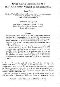
Fig. 1. Sample network and the constructed spanning tree
We illustrate the SST with the sample network shown in Fig. 1. The sample network consists of eight nodes and fifteen links. The root node is a. One possible construction process is as follows. In the step 2 of the SST, we find the cycle (a, g, f, e, h, b, a). The birthdays of these links are set to 1, indicating that they are firstly considered for adding to the SST. We remove [b, a] from the cycle, and add the rest of the links, [a, g], [g, f], [f, e], [e, h] and [h, b], to the tree. The first time step 4 is executed, we find the path (f, d, e). The birthdays of these links are set to 2, because they are secondly considered for adding to the spanning tree. [d, e] is added to the tree. The second time step 4 is executed, and we find the path (b, c, e). The birthdays of these links are set to 3, because they are thirdly considered. [b, c] is added to the tree. At
Proc. of SPIE Vol. 7137 71373G-2
last, we get the TP as shown with dashed links in Fig. 1. The numbers beside the links denote their birthdays. Links [a, h], [g, h], [g, e], [b, e] and [c, d] are assumed to be of birthday zero, because they are not considered during the construction process. For ease of expression, links in TP are referred to as tree links, and the other links are referred to as non-tree links. Table 1 The construction process of the SST in the sample network
Order 1st 2nd 3rd
Path found (a, g, f, e, h, b, a) (f, d, e) (b, c, e)
Links added [a, g], [g, f], [f, e], [e, h], [h, b] [d, e] [b, c]
Links not added [b, a] [f, d] [c, e]
Birthday 1 2 3
{O}
{1} {1} {1) {O}
{'}
\i
{2} 1}
{O}
d
Fig. 2. Another possible construction result
We observe that all the tree links are assigned positive birthdays. Some non-tree links are also assigned positive birthdays. These links will be used for protection. Tab. 1 summarizes the construction process. The second column lists the paths selected in each time. The third column lists the links that are added to TP in each time, and the fourth column lists those that are not added to TP. Note that Fig. 1 is just one of the possible construction results. We will get different spanning trees if we select different paths or remove different links in steps 2 and 4 of the SST. For example, another possible construction process in the sample network is as follows. The root node is still a. In the step 2 of the SST, we find the cycle (a, g, f, e, h, b, a). The birthdays of these links are set to 1. We remove [f, e] from the cycle, and add the rest of the links, [a, g], [g, f], [e, h], [h, b], and [b, a], to the tree. The first time step 4 is executed, we find the path (e, d, c). The birthdays of these links are set to 2. We remove [d, c] from the path, and add [e, d] and [e, c] to the tree. The TP now is shown with dashed links in Fig. 2, and the birthdays are denoted with the numbers beside the links. 2.2 Birthday-based Link Replacing Mechanism It can be observed from Fig. 1 that replacing a tree link with the non-tree link of the same birthday transforms TP into a new spanning tree. For example, replacing [b, c] of birthday 3 with [e, c] of birthday 3 makes a new spanning tree as shown in Fig. 3. This is what we called Birthday-based Link Replacing Mechanism (BLRM), replacing the tree links with the non-tree links of the same birthday. Although the BLRM can handle both link failure and node failure cases, we only discuss the link failure in this subsection, and leave the discussion of the node failure to the next section. Theorem 2, which is proved in [3], describes how the BLRM deals with the single link failure problem, transforming the spanning tree into another spanning tree by replacing the failed tree link with the non-tree link of the same birthday. The replacement is the process of changing the failed tree link to a non-tree link and changing the non-tree link of the same birthday to a tree link. Theorem 2 TP is the Spanning tree constructed by the SST. e is a tree link of birthday x. ex is the non-tree link of the same birthday. Replacing e with ex transforms TP into another spanning tree TP + ex - e.
Proc. of SPIE Vol. 7137 71373G-3
Fig. 3. New spanning tree after transformation
Now, we get the SST-based recovery scheme for link failure. First, we construct a spanning tree using the SST. From Theorem 1, given a two-edge connected network, the SST terminates with a spanning tree. Then, when one tree link fails, the BLRM recovers from failure by replacing the failed link with the non-tree link of the same birthday. From Theorem 2, replacing the failed link with the only non-tree link of the same birthday makes a new spanning tree. Therefore, all the nodes in the network are still connected using this new spanning tree. Take Fig. 1 again as an example. The spanning tree is shown with dashed links. If [b, c] of birthday 3 fails, replacing it with [e, c] of birthday 3 makes a new spanning tree as shown in Fig. 3. As a result, the requirement of the proposed scheme to the network topology is two-edge connected. If the recovery process of the BLRM is fast, arbitrary two-edge connected networks can achieve fast recovery from any single link failure. Note that we can also construct more than one spanning trees by executing the SST several times when needed. Each spanning tree is able to independently recover from failure using the BLRM. That is why we name it as Self-protected Spanning Tree. 2.3 Applying the BLRM to the Node Failure Case We have known from Section 2.2 that when a tree link fails, the BLRM generates a new spanning tree by replacing the failed link with the non-tree link of the same birthday. Now we are dealing with node failure using the BLRM. A node failure is equivalent to the failures of its entire incident tree links. Similarly, to recover from the node failure, the BLRM replaces each failed tree link with the non-tree link of the same birthday. Assume that v is the failed node, for each incident tree link of node v, say e, the replacing rule is as follows. z
Change e to a non-tree link. Let ex denote the only non-tree link that has the same birthday as e. If ex is not the incident link of v, change ex to a tree link.
Note that because v is the failed node, we can not change ex to a tree link when it is the incident link of v. We can see that the BLRM uses the same replacing rule to deal with both link and node failures. That is, when one tree link fails, replace it with its backup link, the non-tree link of the same birthday. Take the spanning tree shown in Fig. 1 as an example. The failure of node e is equivalent with the failure of links [e,h], [e,f] and [e,d], which are all changed to non-tree links. The BLRM recovers from the failure as follows. z The birthday of [e,h] is 1. The non-tree link of birthday 1, [b,a], is not the incident link of the failed node, so change [b,a] to a tree link. z The birthday of [e,f] is 1. The non-tree link of birthday 1, [b,a], is not the incident link of the failed node, so change [b,a] to a tree link. z The birthday of [e,d] is 2. The non-tree link of birthday 2, [d,f], is not the incident link of the failed node, so change [d,f] to a tree link. Now, we get the new spanning tree TP - [e,h] - [e,f] - [e,d] + [b,a] + [d,f] as shown in Fig. 4.
Proc. of SPIE Vol. 7137 71373G-4
0
C®
Fig. 4 In Fig. 1, the BLRM generates a new spanning tree when e fails
However, when node e fails, the spanning tree shown in Fig. 2 can not recover from the failure. In Fig. 2, the failure of node e is equivalent with the failure of links [e,h], [e,c] and [e,d], which are all changed to non-tree links. The BLRM now tries to recover from the failure as follows. z The birthday of [e,h] is 1. However, the non-tree link of birthday 1, [e,f], is the incident link of the failed node, so [e,f] remains to be a non-tree link. z The birthday of [e,c] is 2. The non-tree link of birthday 2, [c,d], is not the incident link of the failed node, so change [c,d] to a tree link. z The birthday of [e,d] is 2. The non-tree link of birthday 2, [c,d], is not the incident link of the failed node, so change [c,d] to a tree link. The generated graph TP - [e,h] - [e,c] - [e,d] + [c,d] as shown in Fig. 5 is not a spanning tree any more.
0
00
Fig. 5 In Fig. 2, the failure of e can not be recovered using the BLRM
We can see that not all the spanning trees constructed by the SST can recover from the node failure using the BLRM. In fact, by slightly modifying the SST, we can get the SST Construction Algorithm for Node failure, named Enhanced SST (ESST), which constructs a spanning tree that can recover from any single node failure using the BLRM. 2.4 Construction Algorithm for Single Enhanced Self-protected Spanning Tree Recovery from Node failure We shall construct a spanning tree that survives any single failure. It is named as the Enhanced Self-protected Spanning Tree, and denoted as TP(VP, EP), where VP is the node set, and EP is the link set. The tree construction algorithm ESST, is illustrates in Algorithm 2. Algorithm 2: ESST Step 1. Set x=1, VP=Ф, EP=Ф. Step 2. Find a cycle (v1,…, vk), k>1. Set the birthdays of all the links in this cycle to 1. Add {v1, …, vk} to VP. Remove one link from the cycle and add the rest of the links to EP. Step 3. If VP=V, stop. Otherwise, x=x+1. Find a path (vx,0, vx,1, …, vx,m), m ≥ 2 such that vx,0 and vx,m are in the VP, vx,0≠vx,m, and the other nodes are not in the tree. Set the birthdays of the links in this path to x. Add {vx,1, …vx,m-1} to VP, Remove one link from the path and add the rest
Proc. of SPIE Vol. 7137 71373G-5
of the links to EP. Go to step 3. Theorem 2 The ESST terminates with a spanning tree if the network is two connected.
Proof: We shall proceed by contradiction. The ESST would fail to terminate with a spanning tree iff, at step 4, no new path could be found but a node in V is never included in VP. We therefore assume that such a node exists. Because the network is two connected, there must be at least two links from V to V \ VP. If there exist two distinct links [z,x] and [y,x] sharing an endpoint x, where x∈V \ VP, and z,y \in V^P, then path (y,x,z) can be selected in step 4. If there do not exist two such edges [z,x] and [y,x], then because of two connectivity there must be at least two distinct nodes x, w∈V \ VP and two distinct nodes z, y∈VP such that [x,z], [w,y]∈ E. If there is a path P from x to w using only nodes in V \ VP, then in step 4, we can select the path that traverses nodes in the following order: z, x, the nodes of path P in order, w and finally y. If there is no such path P, then there is a path P' which has some nodes in VP. Let y' be the last node in P' to be in VP. If y' ≠y, then in step 4, we can select the path that traverses nodes in the following order: y', the nodes in P' between y' and w, w and finally y. If y'=y, then by Menger's theorems [16] and our assumptions there must exist another path P'' from x to w which has some node in VP and which dose not include y. Let y'' be the last node in VP in path P''. Then in step 4, we can select path that traverses nodes in the following order: y'', the nodes in P'' between y'' and w, w and finally y. Thus, in all cases, we have a contradiction. There is only one difference between the SST and the ESST. In step 4 of the SST the selected path (vx,0, vx,1, …, vx,m) may be a cycle. However, in step 4 of the ESST the selected path (vx,0, vx,1, …, vx,m) can not be a cycle, because the ESST specifies that vx,0≠vx,m. Therefore, every spanning tree constructed by the ESST can be constructed by the SST, but not vice versa. Why does not the ESST allow to select a cycle (vx,0, vx,1, …, vx,m) in step 4? Because otherwise the failure of node vx,0 would not be recovered using the BLRM. Let us again take the network shown in Fig. 1 for illustration. The spanning tree shown in Fig. 1 can also be constructed by the ESST, because the spanning tree has not selected a cycle in step 4 during the construction process of this spanning tree. We can verify that the spanning can recover from any single node failure using the BLRM. For example, when node e fails, the BLRM will generate a new spanning tree as shown in Fig. 4. However, the spanning shown in Fig. 2 can not be constructed by the ESST, because the SST has selected cycle (e, d, c, e) in step 4 during the construction process. As shown in Fig. 5, this spanning tree can not recover from the failure of node e using the BLRM. Then, BLRM can handle both signal link and node failure, if the spanning tree is constructed by the ESST. If a link fails, we can transforms TP into another spanning tree by replacing the link of birthday x in TP with the only link of the same birthday not in TP. For example, in fig. 1 replacing failed link [e, f] of birthday 1 with link [a, b] of birthday 1 makes a new spanning tree. A node failure is equivalent to the failures of all its incident tree links. Similarly, to recover from the node failure, the recovery mechanism, named Birthday-based Link Replacing Mechanism (BLRM), replaces each failed link in TP with the link of the same birthday not in TP. For example, in fig. 1, The failure of node e is equivalent with the failures of links [e,h], [e,f] and [e,d]. Then, we use link [b,a] of birthday 1 to replace the failed links [e,h] and [e,f] of birthday 1 and use link [d,f] of birthday 2 to replace the failed link [d,f] of birthday 2. Now, we get a new spanning tree as shown in Fig. 4. Therefore, the spanning tree recovers from failure of e successfully. 2.5 Metro Ethernet Architecture Based on Multiple Enhanced Self-protected Spanning Trees We construct multiple enhanced self-protected spanning trees in metro networks. The method is similar to the proposal in [3], but with the changes of the spanning tree construction algorithm and recovery mechanism to ESST and BLRM, respectively. One or several VLANs are mapped to a spanning tree. Constructing multiple spanning trees makes it possible to use all the links in the network, and provides a flexible way to distribute the network traffic and achieve good load balance. First, we have to decide the number of trees to be constructed. The decision is a trade off between the protocol complexity and the performance [8]. Second, we selected the root nodes for each spanning tree. Because the load of the links near the root node is always much heavier the others links in the tree, we make the distances between
Proc. of SPIE Vol. 7137 71373G-6
any two root nodes as large as possible. This helps to distribute the traffic. Third, we decide the path selection criteria in the ESST to construct the spanning tree. When multiple spanning trees are constructed, each link is used by several spanning trees. Then, If any link or node failes, we select the spanning trees which contain that link or node and let them perform the recovery mechanism BLRM. By using the spanning tree construction algorithm ESST and recovery mechanism BLRM, each selected spanning tree is able to recover from any signal failure independently by replacing the equivalent failed links with the links of the same birthday not in its spanning trees. Therefore, the proposed metro Ethernet architecture can recover not only from a signal link failure, but also from a signal node failure. So, the haleness and survivability of this architecture is enhanced a lot than our previous work of [3].
3. Recovery Time Evaluation and Simulation Results 3.1 Recovery Time Analysis From the illustration of our proposal architecture, we can see that each self-protected spanning tree recovers from the signal link or node failure independently, so the recovery time of the network is determined by that of only one spanning tree. Therefore we use one spanning tree to simulate the recovery time of BLRM after a node failure, which is more complex than a link failure. In the ESST-based recovery scheme, the failure recovery process consists of three steps, failure detection, failure propagation and reconfiguration. The failure recovery time tfr can be expressed as follows. tfr = tfd + tfp + tr where tfd is the time for failure detection, tfp is the time for failure propagation, and tr is the time for reconfiguration. FIPF-+
-_---) \ (a) Failure detection
E® ® Ei----® (b) Failure propagation
(c) Reconfiguration
Fig. 6 Failure recovery process in the sample network
We first take Fig. 1 as an example to briefly illustrate the failure recovery process of the BLRM. When node e fails, the failure recovery process is shown in Fig. 6. Failure detection, as shown in Fig. 6(a), is the first step of the recovery process. The failure of e is equivalent with the failure of three tree links [e,h], [e,f] and [e,d]. Nodes h, f and d will firstly detect the failure. Then, h, f and d broadcast the failure information to all the nodes in the network, as shown in Fig. 6(b), which is the second step of the recovery process. The reconfiguration step, as shown in Fig. 6(c), is the last step of the recovery process. Nodes a, b, f and d activate the corresponding ports to make a new spanning tree. Old failure detection techniques mislead quite a lot of researchers to think that failure detection in Ethernet is slow. For example, in Spanning Tree Protocol (STP) [9] and Rapid Spanning Tree Protocol (RSTP)[10], switches regularly exchange bridge protocol data units (BPDU) every 2 seconds by default to detect a failure, which requires a comparatively long time of several seconds. In Viking [2], SNMP (Simple Network Management Protocol) traps are used for the failure detection, the detection time is in a sub-second range. In fact, failure detection in Ethernet can be very fast, especially in the high speed optical Ethernet. Failure detection functions in SDH are adopted in the 10 Gb/s Ethernet WAN interface, which promises a detection time of around 10 ms [12]. Bidirectional Forwarding Detection (BFD) is another option, which aims to provide fast and low-overhead failure detection between forwarding engines. It is revealed that the failure detection time using BFD is below 20 ms [13], [14]. Therefore, it is reasonable to estimate that tfd = 20 ms. After failure detection step, failure information is broadcasted to notify all the switches. Failure propagation is the step of
Proc. of SPIE Vol. 7137 71373G-7
delivering the failure information to all the switches in the network. The failure information propagation frame (FIPF) is shown in Fig. 7. The FIPF has a special field named "Birthday" to indicate the birthday of the failed link. MAC header and FCS are traditional fields in the MAC frames. The FIPF is padded to meet the minimum length requirement of the MAC frame, and it is assigned the highest priority for the timely delivery. Note that a node failure may result in several different FIPFs. For example, when node e in Fig. 1 fails, two types of FIPFs might be generated to indicate that the failed tree links have the birthdays of 1 and 2 respectively. The FIPFs are forwarded along the broken spanning tree. When the failure propagation finishes, a, g, f, h, b and c know that a link of birthday 1 has failed; d knows that a link of birthday 2 has failed. The time for the failure propagation step is determined by the maximum distance from the switches detecting the failure to all the other switches. In the worst case, the failure information has to traverse the whole spanning tree. Therefore, tfp depends on the diameter of the spanning tree, denoted as D hops. Assume that the failure propagation costs thop ms per hop, then tfp = thop * D ms.
MAC Header (VLAN ID, Type...)
Birthday
PADDING
FCS
Fig. 7 Failure information propagation frame
The reconfiguration step is the last step of the recovery process. Each switch preserves a link birthday table that contains the information of its incident links with positive birthdays. Each item contains the link birthday, and the port state. For ease of understanding, we use only two kinds of port state, "Forwarding" and "Discarding". The "Forwarding" state means the link is a tree link, and the "Discarding" state means the link is a non-tree link. After receiving the FIPF, the switch knows the birthday of the failed link, say x. Then, the switch searches its link birthday table for a match item. A match item is defined as the item that matches the failure information in the FIPF, say: Birthday = x, Port State = Discarding. If the switch finds a match item in its link birthday table, the link in this item is the exact non-tree link, which has the same birthday as the failed link. According to the BLRM, the failed link should be replaced with this link. Therefore, the switch changes the port state of this item to "Forwarding" to make this non-tree link a tree link. Take Fig. 6 as an example. When e fails and the failure propagation finishes, d knows that a link of birthday 2 has failed. Then d notifies f by sending a FIPF with birthday 2. Then d and f makes [f, d] a tree link by changing the corresponding port state to "Forwarding". Similarly, switches a and b change the corresponding port state to "Forwarding" to make [a, b] a tree link. The new spanning tree is then as shown in Fig. 6(c). Moreover, because the topology of the spanning tree has changed, all the switches need to flush out the MAC address tables corresponding to this spanning tree. Global Open Ethernet (GOE) switches[5] with 10 Gb/s interfaces have implemented a similar function, switching Ethernet frames from a failed link to an alternate one, and test results reveal that this kind of recovery switching takes about 2 ms. Therefore, it is reasonable to estimate that tr = 2 ms. According to the analysis, in the worst case, the failure recovery time of the BLRM tfr = 22 ms+ thop * D For example, if thop = 2 ms/hop and D=5 hops, we get tfr = 32 ms. 3.2 Simulation Results We simulate the recovery process of the BLRM in OPNET. As shown in Fig. 8, the ESST is the same as that in Fig. 1. The source station (S) and the destination station (D) are connected with switches g and b respectively. The standard Spanning Tree Algorithm is disabled, and the desired ESST is manually constructed by setting the port states and the port roles of Ethernet switches. Each switch is configured with a link birthday table for the BLRM.
Proc. of SPIE Vol. 7137 71373G-8
During the simulation, the source station transmits the Ethernet frames at a rate of 10 frames/ms. Normally, the packets travel along the path (g, f, e, h, b). Let the node e fail at 100 s. Then the BLRM recovers from the failure by replacing [e,f], [e,d] and [e,h] with [a,b] and [f,d], and the recovery process has been detailed in the last subsection. The failure detection time is set to be 20 ms. When the new spanning tree is generated, the packets travel along the path (g, a, b). We monitor the packets received by the destination station to see the impact of the failure on the traffic flow. The packet arrival rate in the destination station around 100 s is shown in Fig. 9. We can see that the packet arrive rate returns to normal in 26 ms after the failure, which means the recovery time of the BLRM is less than 26 ms in the simulation. It is comparable with the SDH, the currently widely used MAN solution, which promises a recovery time of less than 50 ms.
Packet arrive rate (packcts/ms)
Fig. 8 Network for the simulation of the recovery time
Fig. 9 Packet arrive rate in the destination station
4. Related Work STP is the first resilience method for Ethernet. In STP, a spanning tree is constructed through exchanges of switch ids and port costs. In case of failure, the spanning tree is reconstructed. The main drawback of STP is its slow convergence that could reach up to 50s [15]. RSTP is the successor to STP. It is introduced in IEEE 802.1w [10] and revised in IEEE 802.1D (2004) [9]. RSTP was created to overcome the STP's timer-based slow convergence problem. To eliminate the time for ensuring the convergence of the switches' spanning tree topology state, RSTP uses the proposal-agreement based handshaking mechanism to explicitly synchronize the state among switches. However, recent research shows that the restoration time of RSTP can still reach up to tens of seconds due to the count-to-infinity problem [15]. Other related works, such as Viking [2] and GOE [5], use Multiple Spanning Tree Protocol (MSTP) [11] to address fast recovery issue in Ethernet. Viking [2] uses a central manager node to calculate the protection paths and assign the traffic flows to the paths. SNMP traps are used for failure detection, and the recovery time is in range of sub-second. GOE [5] proposes a per-destination multiple rapid spanning tree protocol as the solution. GOE can provide a very short failure recovery time for an output port having an alternate port, and the recovery time is independent of the number of spanning
Proc. of SPIE Vol. 7137 71373G-9
trees running. However, an output port without alternate route is updated by performing a reconstruction of RSTP tree, which takes a couple of seconds.
5. CONCLUSIONS In this paper, we present a SST-based metro Ethernet architecture, which consists of the tree construction algorithm ESST and the recovery mechanism BLRM. The BLRM is able to transform a spanning tree into a new spanning tree by replacing some tree links with the non-tree links of the same birthday. It is theoretically proved that the ESST based recovery scheme can be applied to arbitrary two connected networks, and makes them achieve fast recovery from any single link or node failure. From the recovery process analysis, we can see that the BLRM is a distributed recovery mechanism. Therefore, to make the whole ESST-based recovery scheme distributed, we are now designing and evaluating the distributed version of the ESST. Moreover, we are also considering designing an effective load balance algorithm based on the BLRM.
REFERENCES [1] D. Allan, N. Bragg, A. McGuire, et al. "Ethernet as carrier transport infrastructure, IEEE Comm. Magazine ", Paper 44(2): 95-101. [2] Sharma S, Gopalan K, Nanda S, et al. "Viking: a multi-spanning-tree Ethernet architecture for metropolitan area and cluster networks ". Proc.INFOCOM, 2283-2294 (2004). [3] W. Chen, X. Zhong, D. Jin, and L. Zeng, Multiple self-protected spanning-trees-based architecture for fast recovery and load balance in metro ethernet," Proc.SPIE 6784, 67840 (2007). [4] David Allan, Nigel Bragg, Alan McGuire, Andy Reid, Ethernet as carrier transport infrastructure, IEEE Communications Magazine, Paper 44(2), 95-101 (2006). [5] A. Iwata, Y. Hidaka, M. Umayabashi et al. Global open Ethernet (GOE) system and its performance evaluation, IEEE Journal on Selected Areas in Communications, Paper 22(11), 1432-1442(2004). [6] Ali M, Chiruvolu G, Ge A. Traffic engineering in metro Ethernet. IEEE Network, Paper 19(2), 10-17(2005). [7] Nenov G. P. C., Bigini G., Valente F. Transporting Ethernet services in metropolitan area networks (MANS), Proc. ICON, 53-59 (2004). [8] S. Tan, G. Waters, J. Crawford. A multiple shared trees approach for application layer multicasting. ICC 2002:1456-1460 [9] IEEE Std 802.1D, IEEE Standard for Local and metropolitan area networks Media Access Control (MAC) Bridges, 1998. [10] IEEE Std 802.1w, IEEE standard for local and metropolitan area networks media access control (MAC) bridges amendment 2: rapid reconfiguration, 2001. [11] IEEE Std 802.1s, IEEE Standards for Local and metropolitan area networks - Virtual Bridged Local Area Networks - Amendment 3: Multiple Spanning Trees, 2002. [12] J.-P. Vasseur, M. Pickavet, P. Demeester, Network recovery: protection and restoration of optical, SONET-SDH,and MPLS. Morgan Kaufmann, 2004. [13] O. Bonaventure, C. Filsfils, P. Francois, Achieving Sub-50 Milliseconds Recovery Upon BGP Peering Link Failures, IEEE/ACM Trans. Networking, Paper 15(5): 1123-1135 (2007). [14] P. Francois, C. Filsfils, J. Evans, O. Bonaventure, Achieving sub-second IGP convergence in large IP networks, ACM SIGCOMM Compter Communication Review, Paper 35(2): 35-44(2005). [15] K. Elmeleegy, A.L. Cox, T.S.E. Ng, On count-to-infinity induced forwarding loops in Ethernet networks, Proc. IEEE INFOCOM, Barcelona, Spain, 1-13(2006). [16] M. Medard, S.G. Finn, R.A. Barry, R.G. Gallager, Redundant trees for preplanned recovery in arbitrary vertexredundant or edge-redundant graphs, IEEE/ACM Trans.Networking, Paper 7(5): 641-652(1999).
Proc. of SPIE Vol. 7137 71373G-10